EP0683415B1 - Optical enclosure for high speed rotating beam deflector - Google Patents
Optical enclosure for high speed rotating beam deflector Download PDFInfo
- Publication number
- EP0683415B1 EP0683415B1 EP95200690A EP95200690A EP0683415B1 EP 0683415 B1 EP0683415 B1 EP 0683415B1 EP 95200690 A EP95200690 A EP 95200690A EP 95200690 A EP95200690 A EP 95200690A EP 0683415 B1 EP0683415 B1 EP 0683415B1
- Authority
- EP
- European Patent Office
- Prior art keywords
- optical
- enclosure
- deflector
- fan
- exit
- Prior art date
- Legal status (The legal status is an assumption and is not a legal conclusion. Google has not performed a legal analysis and makes no representation as to the accuracy of the status listed.)
- Expired - Lifetime
Links
- 230000003287 optical effect Effects 0.000 title claims description 66
- 230000005855 radiation Effects 0.000 claims description 7
- 230000033001 locomotion Effects 0.000 claims description 5
- 239000005304 optical glass Substances 0.000 claims 1
- 230000002093 peripheral effect Effects 0.000 claims 1
- 238000007789 sealing Methods 0.000 claims 1
- 238000003384 imaging method Methods 0.000 description 7
- 230000005534 acoustic noise Effects 0.000 description 3
- 239000000356 contaminant Substances 0.000 description 3
- 238000011109 contamination Methods 0.000 description 3
- 230000000694 effects Effects 0.000 description 3
- 238000005260 corrosion Methods 0.000 description 2
- 230000007797 corrosion Effects 0.000 description 2
- 239000000463 material Substances 0.000 description 2
- 238000009987 spinning Methods 0.000 description 2
- 238000010521 absorption reaction Methods 0.000 description 1
- 229910052782 aluminium Inorganic materials 0.000 description 1
- XAGFODPZIPBFFR-UHFFFAOYSA-N aluminium Chemical compound [Al] XAGFODPZIPBFFR-UHFFFAOYSA-N 0.000 description 1
- 238000013459 approach Methods 0.000 description 1
- 230000009286 beneficial effect Effects 0.000 description 1
- 230000005540 biological transmission Effects 0.000 description 1
- 239000002131 composite material Substances 0.000 description 1
- 230000001419 dependent effect Effects 0.000 description 1
- 229910052751 metal Inorganic materials 0.000 description 1
- 239000002184 metal Substances 0.000 description 1
- 238000000034 method Methods 0.000 description 1
- 239000002245 particle Substances 0.000 description 1
- 238000005086 pumping Methods 0.000 description 1
- 238000010008 shearing Methods 0.000 description 1
- 230000001629 suppression Effects 0.000 description 1
- 238000010408 sweeping Methods 0.000 description 1
Images


Classifications
-
- G—PHYSICS
- G02—OPTICS
- G02B—OPTICAL ELEMENTS, SYSTEMS OR APPARATUS
- G02B26/00—Optical devices or arrangements for the control of light using movable or deformable optical elements
- G02B26/08—Optical devices or arrangements for the control of light using movable or deformable optical elements for controlling the direction of light
- G02B26/10—Scanning systems
Definitions
- the invention is related to optical scanning systems using a high speed rotating optical element and more specifically, a rotating optical element that causes turbulent airflow, thermal effects, and pressure disturbances in its surrounding area, resulting in optical distortions and acoustical noise problems.
- Optical scanners such as those used in film recorders, operate at very high scan rates, causing the optical deflector to rotate through the air at very high speeds.
- the Reynolds number for a typical deflector rotating at 27,000 rpm approaches 60,000.
- the airflow therefore is in the turbulent regime and consequently optical and acoustical problems arise.
- the optical deflector generates heat from shearing the air and in a turbulent air flow regime, heat transfer occurs via macroscopic pockets of air at differing temperatures, resulting in non-uniform air temperature. This circumstance can cause optical errors since the refractive index of air changes with temperature change. This causes wavefront errors in the deflected beam which degrade the writing spot of the scanned beam at the image recording surface.
- the spinning of the optical deflector often produces an offensive acoustic noise due to the pressure disturbances caused by the irregularly shaped deflector moving through the air.
- the airflow around the optical deflector becomes increasingly turbulent, causing increased optical distortion and acoustical noise.
- optical scanners Another problem encountered in optical scanners is the fouling of the optical deflector by airborne contaminants. During operation, optical scanners tend to draw air in toward the spin axis of the optical deflector and discharge air out radially from the spinning optical deflector. Particles in the flowing air can both foul and corrode the mirror surface of the optical deflector over time, reducing the quality of the scanned beam.
- Miyagawa et al. fail to recognise the problem solved by the present invention, namely, to reduce air flow in the region of the rotating deflector, to reduce acoustic noise associated with the rotating deflector and to prevent contamination of the optical deflector by air borne contaminants by extending the enclosure toward the scan surface as detailed below.
- the invention comprises an optical scanner having an optical element, a motor for rotating the optical element about a spin axis, and enclosure means enclosing the optical element to reduce turbulent airflow surrounding the optical element.
- the enclosure also equalizes air temperature surrounding the optical element during rotation of the optical element by the motor.
- an optical scanner generally referred to by reference numeral (10) having a spin motor (12) for rotating an optical deflector (14).
- the deflector (14) is coupled to a spin motor shaft (16) to rotate therewith upon operation of the spin motor (12).
- An input beam (18) is shown directed toward the deflector (14) parallel to a spin axis (20) of the deflector (14).
- the input beam (18) is deflected by the optical deflector (14) and a resulting exit beam (19) is projected onto a scan surface (not shown) and scanned by the rotating deflector (14) in a sweeping motion, forming a scan line (not shown) on the scan surface.
- a hollow, non-rotating enclosure or shield (24) generally cylindrical in shape has a first end (26) abutting against the spin motor (12) to enclose the rotating deflector (14).
- the shield (24) extends longitudinally along the spin axis (20) and has an entrance window (30) affixed to a beam entrance aperture (32) at a second end (34) thereof.
- a seal (36) is provided at the interface of the first end (26) of the shield (24) and the spin motor (12).
- the entrance window (30) serves to seal the beam entrance aperture (32) of the shield (24).
- a beam exit aperture (38) on an outer radial portion (40) of the shield (24) is perpendicular to the spin axis (20) and extends along the perimeter of the cylindrical body of the shield (24), allowing the exit beam (19) to scan through a range of angles.
- the shield (24) is made of a material such as aluminum, however can alternatively be made from plastic, metal, or a composite material.
- the geometry is made to closely and smoothly match the shape of the rotating deflector (14) so as to reduce the volume of air surrounding the deflector and minimize turbulence due to form drag.
- pressure disturbances caused by the irregularly shaped rotating deflector are minimized, as is the associated acoustical noise. Further, the acoustical noise is reduced because the sound has less air volume to radiate through and the sound transmission must travel through the shield.
- the shield reduces optical distortions of the beam in three ways.
- the reduction in air turbulence corresponds to a reduction in optical distortions.
- the shield being sealed at the beam entrance where air can be drawn in, fouling of the deflector is eliminated. By prohibiting corrosion and contamination of the deflector, scatter and absorption are less likely to occur so that the entire beam energy is deflected.
- the optical shield described can be used in various types of imaging systems.
- the optical shield is shown in a capstan type imagesetter, where the output beam (19) is scanned onto a planar surface (42).
- An output lens (44) (F- ⁇ lens) is provided at the beam exit aperture (38) on the outer radial portion (40) of the shield (24) and serves to seal the beam exit aperture (38) via an optical mounting member (46) which supports the output lens (44).
- the mounting member (46) is a hollow rectangular attachment to the optical shield (24) which extends outwardly from the beam exit aperture (38).
- FIG. 4 A preferred embodiment of the invention is shown in Figs. 4 and 5 (with corresponding elements indicated by the same reference numerals as previously), having a hollow, non-rotating enclosure or shield, generally referred to by reference numeral (50), that has a cylindrical body (52) substantially identical to the previous embodiment, and a fan-like portion (54) extending radially outward from the cylindrical body (52).
- a first end (26) of the cylindrical body abuts against the spin motor (12).
- An entrance window (30) is provided at a beam entrance aperture (32) at a second end (34) of the cylindrical body (52), and serves to seal the shield (50).
- a beam exit aperture (38) (Fig.
- the exit aperture (38) of the cylindrical body (52) has two fan-like members (56, 58) extending radially outward therefrom and ending at a beam exit slot 60.
- the fan-like members (56, 58) are spaced axially apart along the spin axis, allowing the exit beam (19) to project radially outward from the cylindrical body (52), in-between the fan-like members (56, 58).
- the two fan-like members (56, 58) are joined together in two areas (62, 64) extending outward on a tangent from the cylindrical body.
- the fan-like portion (54) extends radially with respect to the spin axis (20) over an area from a beginning of the exit beam aperture (0°) to an ending of the exit beam aperture (180°).
- the beam exit slot (60) can be left open or is preferably enclosed by a thin transmissive exit window (66) (Fig. 4).
- the fan-like members (56, 58) provide additional noise suppression.
- the design of the fan-like portion (54) has a smooth tapered shape (62, 64) as it extends out from the cylindrical body (52), which provides optimal imaging quality.
- the angled surface (55) of the rotating beam deflector pumps air within the shield (50).
- the tapered portions (62, 64) provide an aerodynamic inner shield surface, minimizing optical distortion caused by pressure gradients in the surrounding air.
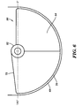
- Fig. 6 shows a giant optical shield (50) used in an internal drum (68) imagesetter.
- the fan-like portion (54) extends to the maximum length along the beam exit path allowed by the configuration of the internal drum (68), while allowing clearance (70) for axial movement of the shield (50) along the inside of the drum (68).
- This particular configuration prevents undesirable reflections of the scan beam off of the scan surface (68) from reflecting back to the scanner hardware. Such inadvertent back reflections can in turn be reflected by the scanner hardware, causing arbitrary exposure of photosensitive media being imaged, resulting in undesirable artifacts in the image.
- the extended fan-like portion (54) only allows the light beam from the beam deflector (55) (Fig. 4) to scan on the imaging surface (68) within the scan line being scanned, thereby eliminating artifacts in other scan lines due to any other unintentional light exposure to the media.
- heat near the surface of the drum (68) is distributed throughout the drum interior by the movement of the shield (50) and the enclosed optics across the drum surface (68).
- the shield (50) is moved across the drum surface (68) during the scanning process. Because the fan-like portion (54) extends as far as the drum surface, the heat is pushed away from the surface and distributed by the air movement outside of the shield (50) and by the thermal conductivity of the shield material. Therefore, the scan beam inside of the shield scans across a scan line in a more uniform temperature field. As a result, the undesirable effects of a non-uniform temperature field, as described above, are accordingly reduced, as are optical distortions resulting therefrom.
- the giant shield embodiment is shown having one side of the fan-like portion (54) with a smooth tapered outer shape (72) as it extends out from the cylindrical body (52), as described in the previous embodiment.
- the tangential tapered design (72) is most beneficial on the side of the cylindrical body (52) where the beam deflector turns from scanning through the exit beam aperture (38) back into the cylindrical body portion (52) (left side as viewed in Fig. 6).
- the angled surface (55) turns out of the fan-like portion (54) on the left side and rotates back into the cylindrical body (52).
- Pressure is built up at the junction of the fan-like portion (54) and the cylindrical body (52) due to the pumping action of the angled surface (55).
- tapered design (72) minimizes the pressure and imaging quality is thereby maintained.
- the angled surface (55) rotating back into the fan-like portion (54) of the shield (50) to scan through the exit beam aperture (38) there is little pressure build-up so a tapered surface is not required.
Landscapes
- Physics & Mathematics (AREA)
- General Physics & Mathematics (AREA)
- Optics & Photonics (AREA)
- Mechanical Optical Scanning Systems (AREA)
- Laser Beam Printer (AREA)
- Facsimile Scanning Arrangements (AREA)
Description
- The invention is related to optical scanning systems using a high speed rotating optical element and more specifically, a rotating optical element that causes turbulent airflow, thermal effects, and pressure disturbances in its surrounding area, resulting in optical distortions and acoustical noise problems.
- Optical scanners, such as those used in film recorders, operate at very high scan rates, causing the optical deflector to rotate through the air at very high speeds. The Reynolds number for a typical deflector rotating at 27,000 rpm approaches 60,000. The airflow therefore is in the turbulent regime and consequently optical and acoustical problems arise. The optical deflector generates heat from shearing the air and in a turbulent air flow regime, heat transfer occurs via macroscopic pockets of air at differing temperatures, resulting in non-uniform air temperature. This circumstance can cause optical errors since the refractive index of air changes with temperature change. This causes wavefront errors in the deflected beam which degrade the writing spot of the scanned beam at the image recording surface.
- As the geometry of the optical deflector is seldom optimum for rotation, the spinning of the optical deflector often produces an offensive acoustic noise due to the pressure disturbances caused by the irregularly shaped deflector moving through the air. As the rotational rate of the optical scanner increases, the airflow around the optical deflector becomes increasingly turbulent, causing increased optical distortion and acoustical noise.
- Another problem encountered in optical scanners is the fouling of the optical deflector by airborne contaminants. During operation, optical scanners tend to draw air in toward the spin axis of the optical deflector and discharge air out radially from the spinning optical deflector. Particles in the flowing air can both foul and corrode the mirror surface of the optical deflector over time, reducing the quality of the scanned beam.
- It is known in the art of optical scanners to enclose a light beam deflector within a hollow enclosure sealed by a transparent window mounted in an entrance aperture of the hollow enclosure. One such system is disclosed in US 4,930,869 by Miyagawa et al. which teaches a hollow enclosure for surrounding a rotating deflector element and a transparent window mounted in an aperture of the hollow enclosure and inclined with respect to an input radiation beam entrance incident angle. The input radiation beam passes through the transparent window, is reflected by the rotating deflector element and exits the enclosure through the transparent window mounted in the entrance aperture. The exit beam then continues on to a scan surface. The transparent window of Miyagawa et al. is inclined at such an angle with respect to the input radiation beam so as to offset reflectance losses which result when the deflector rotates. Miyagawa et al., however, fail to recognise the problem solved by the present invention, namely, to reduce air flow in the region of the rotating deflector, to reduce acoustic noise associated with the rotating deflector and to prevent contamination of the optical deflector by air borne contaminants by extending the enclosure toward the scan surface as detailed below.
- Accordingly it is an object of the present invention to enclose a rotating optical deflector with a fixed (non-rotating) shield to reduce the airflow surrounding the optical deflector and thereby improve the image quality of a scanning system employing such a rotating optical deflector.
- It is another object of the invention to reduce acoustic noise associated with a high speed rotating optical deflector,
- It is another object of the invention to prevent contamination of an optical deflector by airborne contaminants and prevent corrosion of the deflector surface.
- It is another object of the invention to equalize the air temperature surrounding the optical deflector.
- It is another object of the invention to prevent reflections from an imaging surface from inadvertently being deflected by the optical deflector back to the imaging surface and causing unintentional imaging errors.
- The invention comprises an optical scanner having an optical element, a motor for rotating the optical element about a spin axis, and enclosure means enclosing the optical element to reduce turbulent airflow surrounding the optical element. The enclosure also equalizes air temperature surrounding the optical element during rotation of the optical element by the motor.
- The above mentioned objects are realized by the specific features according to claim 1. Preferred embodiments of the invention are set out in the dependent claims.
- The features and objects of the invention will become apparent in the following description taken with the accompanying drawings, in which:
- Figure 1 is a side elevation view in partial section of an optical shield, not according to the present invention, used in a rotating optical scanner;
- Figure 2 is an isometric view of the optical shield of Fig. 1;
- Figure 3 is an isometric view of an embodiment of an optical shield used with an output lens typical of a capstan type imagesetter;
- Figure 4 is a side elevation view in partial section of an embodiment of an optical shield according to the present invention used in a rotating optical scanner;
- Figure 5 is an isometric view of the optical shield of Fig. 4; and
- Figure 6 is a front end view of an optical shield having an extended fan-like portion used in an internal drum imagesetter.
-
- Referring to Fig. 1, an optical scanner, generally referred to by reference numeral (10), is shown having a spin motor (12) for rotating an optical deflector (14). The deflector (14) is coupled to a spin motor shaft (16) to rotate therewith upon operation of the spin motor (12). An input beam (18) is shown directed toward the deflector (14) parallel to a spin axis (20) of the deflector (14). The input beam (18) is deflected by the optical deflector (14) and a resulting exit beam (19) is projected onto a scan surface (not shown) and scanned by the rotating deflector (14) in a sweeping motion, forming a scan line (not shown) on the scan surface.
- Referring to Figs. 1 and 2, a hollow, non-rotating enclosure or shield (24) generally cylindrical in shape has a first end (26) abutting against the spin motor (12) to enclose the rotating deflector (14). The shield (24) extends longitudinally along the spin axis (20) and has an entrance window (30) affixed to a beam entrance aperture (32) at a second end (34) thereof. A seal (36) is provided at the interface of the first end (26) of the shield (24) and the spin motor (12). The entrance window (30) serves to seal the beam entrance aperture (32) of the shield (24). A beam exit aperture (38) on an outer radial portion (40) of the shield (24) is perpendicular to the spin axis (20) and extends along the perimeter of the cylindrical body of the shield (24), allowing the exit beam (19) to scan through a range of angles.
- The shield (24) is made of a material such as aluminum, however can alternatively be made from plastic, metal, or a composite material. The geometry is made to closely and smoothly match the shape of the rotating deflector (14) so as to reduce the volume of air surrounding the deflector and minimize turbulence due to form drag. By enclosing the rotating optical deflector in the shield, pressure disturbances caused by the irregularly shaped rotating deflector are minimized, as is the associated acoustical noise. Further, the acoustical noise is reduced because the sound has less air volume to radiate through and the sound transmission must travel through the shield.
- The shield reduces optical distortions of the beam in three ways. First, the air turbulence is reduced by the closely fitting shield around the deflector. The reduction in air turbulence corresponds to a reduction in optical distortions. Second, the temperature is more uniform due to an insulating effect of the shield. With less change in the temperature of the air surrounding the deflector, the beam being deflected is less likely to have wavefront errors because of a change in the refractive index of the surrounding air. Thirdly, with the shield being sealed at the beam entrance where air can be drawn in, fouling of the deflector is eliminated. By prohibiting corrosion and contamination of the deflector, scatter and absorption are less likely to occur so that the entire beam energy is deflected.
- The optical shield described can be used in various types of imaging systems. In Fig. 3, the optical shield is shown in a capstan type imagesetter, where the output beam (19) is scanned onto a planar surface (42). An output lens (44) (F- lens) is provided at the beam exit aperture (38) on the outer radial portion (40) of the shield (24) and serves to seal the beam exit aperture (38) via an optical mounting member (46) which supports the output lens (44). The mounting member (46) is a hollow rectangular attachment to the optical shield (24) which extends outwardly from the beam exit aperture (38).
- A preferred embodiment of the invention is shown in Figs. 4 and 5 (with corresponding elements indicated by the same reference numerals as previously), having a hollow, non-rotating enclosure or shield, generally referred to by reference numeral (50), that has a cylindrical body (52) substantially identical to the previous embodiment, and a fan-like portion (54) extending radially outward from the cylindrical body (52). A first end (26) of the cylindrical body abuts against the spin motor (12). An entrance window (30) is provided at a beam entrance aperture (32) at a second end (34) of the cylindrical body (52), and serves to seal the shield (50). A beam exit aperture (38) (Fig. 4) on an outer radial portion (40) of the cylindrical body (52) is perpendicular to the spin axis (20) and extends along half of the periphery of the cylindrical body (52), allowing the exit beam (19) to scan from 0° to 180° when the angled surface (55) of the beam deflector rotates through the exit beam aperture. It will be appreciated that the beam exit aperture (38) may extend less or more along the periphery of the cylindrical body (52), depending on the angle which the beam is to be scanned through. The exit aperture (38) of the cylindrical body (52) has two fan-like members (56, 58) extending radially outward therefrom and ending at a
beam exit slot 60. The fan-like members (56, 58) are spaced axially apart along the spin axis, allowing the exit beam (19) to project radially outward from the cylindrical body (52), in-between the fan-like members (56, 58). The two fan-like members (56, 58) are joined together in two areas (62, 64) extending outward on a tangent from the cylindrical body. The fan-like portion (54) extends radially with respect to the spin axis (20) over an area from a beginning of the exit beam aperture (0°) to an ending of the exit beam aperture (180°). The beam exit slot (60) can be left open or is preferably enclosed by a thin transmissive exit window (66) (Fig. 4). The fan-like members (56, 58) provide additional noise suppression. The design of the fan-like portion (54) has a smooth tapered shape (62, 64) as it extends out from the cylindrical body (52), which provides optimal imaging quality. The angled surface (55) of the rotating beam deflector pumps air within the shield (50). The tapered portions (62, 64) provide an aerodynamic inner shield surface, minimizing optical distortion caused by pressure gradients in the surrounding air. - Fig. 6 shows a giant optical shield (50) used in an internal drum (68) imagesetter. The fan-like portion (54) extends to the maximum length along the beam exit path allowed by the configuration of the internal drum (68), while allowing clearance (70) for axial movement of the shield (50) along the inside of the drum (68). This particular configuration prevents undesirable reflections of the scan beam off of the scan surface (68) from reflecting back to the scanner hardware. Such inadvertent back reflections can in turn be reflected by the scanner hardware, causing arbitrary exposure of photosensitive media being imaged, resulting in undesirable artifacts in the image. The extended fan-like portion (54) only allows the light beam from the beam deflector (55) (Fig. 4) to scan on the imaging surface (68) within the scan line being scanned, thereby eliminating artifacts in other scan lines due to any other unintentional light exposure to the media.
- Additionally, heat near the surface of the drum (68) is distributed throughout the drum interior by the movement of the shield (50) and the enclosed optics across the drum surface (68). The shield (50) is moved across the drum surface (68) during the scanning process. Because the fan-like portion (54) extends as far as the drum surface, the heat is pushed away from the surface and distributed by the air movement outside of the shield (50) and by the thermal conductivity of the shield material. Therefore, the scan beam inside of the shield scans across a scan line in a more uniform temperature field. As a result, the undesirable effects of a non-uniform temperature field, as described above, are accordingly reduced, as are optical distortions resulting therefrom.
- The giant shield embodiment is shown having one side of the fan-like portion (54) with a smooth tapered outer shape (72) as it extends out from the cylindrical body (52), as described in the previous embodiment. The tangential tapered design (72) is most beneficial on the side of the cylindrical body (52) where the beam deflector turns from scanning through the exit beam aperture (38) back into the cylindrical body portion (52) (left side as viewed in Fig. 6). For clockwise rotation of the angled reflective surface (55) (Fig. 4) of the beam deflector, the angled surface (55) turns out of the fan-like portion (54) on the left side and rotates back into the cylindrical body (52). Pressure is built up at the junction of the fan-like portion (54) and the cylindrical body (52) due to the pumping action of the angled surface (55). However the tapered design (72) minimizes the pressure and imaging quality is thereby maintained. Upon the angled surface (55) rotating back into the fan-like portion (54) of the shield (50) to scan through the exit beam aperture (38), there is little pressure build-up so a tapered surface is not required.
Claims (4)
- An optical scanner for receiving an input radiation beam (18) and deflecting said input radiation beam (18) to provide a resulting exit beam (19) which sweeps across a scanning surface (68), said optical scanner, comprising:characterised in that said enclosure (24) includes an arcuate portion (54) formed by opposing fan-like members (56, 58) each extending radially with respect to said spin axis (20) beginning at said exit aperture (38) and extending toward said scanning surface (68), said fan-like members (56, 58) being spaced apart for allowing said exit beam (19) to project radially outward, with respect to said spin axis (20), from said enclosure (24) and pass between said fan-like members (56, 58).(a) an optical element (14) for deflecting the input radiation beam (18);(b) a rotation system (12) for rotating said optical element (14) about a spin axis (20);(c) an enclosure (24) having a hollow cylindrical body for enclosing said optical element, said enclosure (24) being non-rotationally supported with respect to said rotation system (12), and including an entrance aperture (32) at a first end, for receiving said input radiation beam (18) therethrough, and an exit aperture (38) forming a slot in a peripheral portion (40) of said enclosure (24) through which said resulting exit beam (18) passes;
- The optical scanner according to claim 1 wherein said fan-like members (56, 58) are joined together in two areas (62, 64) extending outward on a tangent from said enclosure (24).
- The optical scanner according to any one of the above claims further comprising optical glass window means (30) for sealing said enclosure (24) at said entrance aperture (32).
- The optical scanner according to any one of the above claims wherein said arcuate portion (54) extends substantially from said exit aperture (38) to said scanning surface (68) while allowing sufficient clearance (70) between said arcuate portion (54) and said scanning surface (68) for axial movement of the enclosure (24) along the scanning surface (68).
Applications Claiming Priority (2)
| Application Number | Priority Date | Filing Date | Title |
|---|---|---|---|
| US243677 | 1988-09-13 | ||
| US08/243,677 US5589973A (en) | 1994-05-16 | 1994-05-16 | Optical enclosure for high speed rotating beam deflector |
Publications (2)
| Publication Number | Publication Date |
|---|---|
| EP0683415A1 EP0683415A1 (en) | 1995-11-22 |
| EP0683415B1 true EP0683415B1 (en) | 2000-07-12 |
Family
ID=22919675
Family Applications (1)
| Application Number | Title | Priority Date | Filing Date |
|---|---|---|---|
| EP95200690A Expired - Lifetime EP0683415B1 (en) | 1994-05-16 | 1995-03-21 | Optical enclosure for high speed rotating beam deflector |
Country Status (4)
| Country | Link |
|---|---|
| US (1) | US5589973A (en) |
| EP (1) | EP0683415B1 (en) |
| JP (1) | JP2945608B2 (en) |
| DE (1) | DE69517869T2 (en) |
Families Citing this family (30)
| Publication number | Priority date | Publication date | Assignee | Title |
|---|---|---|---|---|
| US5600477A (en) * | 1995-05-04 | 1997-02-04 | Bayer Corporation | Beam scanner |
| DE19517629A1 (en) * | 1995-05-13 | 1996-11-14 | Hell Ag Linotype | Beam deflector |
| US5610751A (en) * | 1995-11-14 | 1997-03-11 | Speedring Systems, Inc. | Optical scanning device having a spherical exit window |
| DE19624203A1 (en) * | 1996-06-18 | 1998-01-02 | Hell Ag Linotype | Rotating mirror unit for scanning or recording image information with a cover surrounding the rotating mirror |
| GB9710021D0 (en) * | 1997-05-16 | 1997-07-09 | Fujifilm Electronic Imaging Li | A method of reducing the effect of a contaminated environment |
| DE19820784C2 (en) * | 1998-03-21 | 2003-05-08 | Heidelberger Druckmasch Ag | Light beam deflection |
| US5901000A (en) * | 1998-04-22 | 1999-05-04 | Lexmark International, Inc. | Sound reduced rotatable polygon assembly |
| US6243184B1 (en) * | 1998-10-09 | 2001-06-05 | Ecrm, Inc. | Method and apparatus for light scanning |
| US6735003B1 (en) | 1998-10-29 | 2004-05-11 | Agfa Corporation | Method and apparatus for reducing artifacts in an imaging system |
| US6501584B1 (en) | 2001-08-14 | 2002-12-31 | Lexmark International, Inc. | Sound reduced rotatable polygon assembly |
| US7381980B2 (en) | 2003-01-09 | 2008-06-03 | Idexx Laboratories, Inc. | Method and apparatus for improving a computed radiography image |
| TWI448830B (en) * | 2010-02-09 | 2014-08-11 | Asml荷蘭公司 | Microlithography device and component manufacturing method |
| KR101419330B1 (en) | 2010-02-23 | 2014-07-15 | 에이에스엠엘 네델란즈 비.브이. | Lithographic apparatus and device manufacturing method |
| WO2011104172A1 (en) | 2010-02-25 | 2011-09-01 | Asml Netherlands B.V. | Lithographic apparatus and device manufacturing method |
| US9696633B2 (en) | 2010-04-12 | 2017-07-04 | Asml Netherlands B.V. | Substrate handling apparatus and lithographic apparatus |
| WO2012076300A1 (en) | 2010-12-08 | 2012-06-14 | Asml Netherlands B.V. | Lithographic apparatus and device manufacturing method |
| JP5793236B2 (en) | 2011-03-29 | 2015-10-14 | エーエスエムエル ネザーランズ ビー.ブイ. | Measurement of the position of the radiation beam spot in lithography. |
| KR101538414B1 (en) | 2011-04-08 | 2015-07-22 | 에이에스엠엘 네델란즈 비.브이. | Lithographic apparatus, programmable patterning device and lithographic method |
| KR101579916B1 (en) | 2011-04-21 | 2015-12-23 | 에이에스엠엘 네델란즈 비.브이. | Lithographic apparatus, method for maintaining a lithographic apparatus and device manufacturing method |
| JP5837693B2 (en) | 2011-08-18 | 2015-12-24 | エーエスエムエル ネザーランズ ビー.ブイ. | Lithographic apparatus and device manufacturing method |
| NL2009342A (en) | 2011-10-31 | 2013-05-07 | Asml Netherlands Bv | Lithographic apparatus and device manufacturing method. |
| NL2009761A (en) | 2011-11-29 | 2013-05-30 | Asml Netherlands Bv | Lithographic apparatus, device manufacturing method and computer program. |
| WO2013079316A2 (en) | 2011-11-29 | 2013-06-06 | Asml Netherlands B.V. | Apparatus and method for converting a vector-based representation of a desired device pattern for a lithography apparatus, apparatus and method for providing data to a programmable patterning device, a lithography apparatus and a device manufacturing method |
| US9341960B2 (en) | 2011-12-05 | 2016-05-17 | Asml Netherlands B.V. | Lithographic apparatus and device manufacturing method |
| US9488921B2 (en) | 2011-12-06 | 2016-11-08 | Asml Netherlands B.V. | Lithography apparatus, an apparatus for providing setpoint data, a device manufacturing method, a method of calculating setpoint data and a computer program |
| NL2009902A (en) | 2011-12-27 | 2013-07-01 | Asml Netherlands Bv | Lithographic apparatus and device manufacturing method. |
| US9354502B2 (en) | 2012-01-12 | 2016-05-31 | Asml Netherlands B.V. | Lithography apparatus, an apparatus for providing setpoint data, a device manufacturing method, a method for providing setpoint data and a computer program |
| KR101633761B1 (en) | 2012-01-17 | 2016-06-27 | 에이에스엠엘 네델란즈 비.브이. | Lithographic apparatus and device manufacturing method |
| KR101650830B1 (en) | 2012-02-23 | 2016-08-24 | 에이에스엠엘 네델란즈 비.브이. | Device, lithographic apparatus, method for guiding radiation and device manufacturing method |
| NL2012052A (en) | 2013-01-29 | 2014-08-04 | Asml Netherlands Bv | A radiation modulator for a lithography apparatus, a lithography apparatus, a method of modulating radiation for use in lithography, and a device manufacturing method. |
Family Cites Families (11)
| Publication number | Priority date | Publication date | Assignee | Title |
|---|---|---|---|---|
| JPS554019A (en) * | 1978-06-22 | 1980-01-12 | Canon Inc | Light deflector |
| JPS55129313A (en) * | 1979-03-29 | 1980-10-07 | Canon Inc | Light deflector |
| DE3303499A1 (en) * | 1982-02-05 | 1983-08-25 | Nippon Seiko K.K., Tokyo | DYNAMIC GAS STORAGE |
| EP0096089A1 (en) * | 1982-06-04 | 1983-12-21 | DR.-ING. RUDOLF HELL GmbH | Optical deflexion system |
| JPS60244913A (en) * | 1984-05-21 | 1985-12-04 | Toshiba Corp | Supporting device for rotating body |
| US4560244A (en) * | 1984-06-25 | 1985-12-24 | Solavolt International | Apparatus and method for redirecting an incident beam |
| US4943128A (en) * | 1986-10-28 | 1990-07-24 | Ricoh Company, Ltd. | Light scanning device |
| JPH01131516A (en) * | 1987-08-07 | 1989-05-24 | Fuji Photo Film Co Ltd | Optical beam scanner |
| US5080456A (en) * | 1990-02-26 | 1992-01-14 | Symbol Technologies, Inc. | Laser scanners with extended working range |
| IT1266063B1 (en) * | 1992-01-30 | 1996-12-20 | Miriam Lunelli | POLAR VISION LASER SCANNER FOR LONG DISTANCES |
| JP3239188B2 (en) * | 1992-02-28 | 2001-12-17 | コニカ株式会社 | Light beam scanning device |
-
1994
- 1994-05-16 US US08/243,677 patent/US5589973A/en not_active Expired - Fee Related
-
1995
- 1995-03-21 DE DE69517869T patent/DE69517869T2/en not_active Expired - Fee Related
- 1995-03-21 EP EP95200690A patent/EP0683415B1/en not_active Expired - Lifetime
- 1995-05-11 JP JP7135617A patent/JP2945608B2/en not_active Expired - Fee Related
Also Published As
| Publication number | Publication date |
|---|---|
| DE69517869T2 (en) | 2001-01-18 |
| DE69517869D1 (en) | 2000-08-17 |
| JP2945608B2 (en) | 1999-09-06 |
| JPH0843755A (en) | 1996-02-16 |
| EP0683415A1 (en) | 1995-11-22 |
| US5589973A (en) | 1996-12-31 |
Similar Documents
| Publication | Publication Date | Title |
|---|---|---|
| US5589973A (en) | Optical enclosure for high speed rotating beam deflector | |
| EP0814358B1 (en) | Rotating beam deflector having an integral wavefront correction element | |
| US20040017469A1 (en) | Optical scanning device | |
| EP1099974B1 (en) | Optical scanning apparatus and image-forming apparatus | |
| EP0889353B1 (en) | Optical deflecting-scanning apparatus | |
| JP2650231B2 (en) | Ray / deflecting device | |
| US5757532A (en) | Optical scanner | |
| US5526168A (en) | Light beam deflection means | |
| JPH10260370A (en) | Raster scanning system | |
| US5877887A (en) | Light beam deflection means | |
| JP3137656B2 (en) | A rotating mirror unit for scanning or recording image information, with a cover surrounding the rotating mirror | |
| JP3274779B2 (en) | Optical scanning device | |
| JP2918065B2 (en) | Ray deflecting device | |
| JPH11183837A5 (en) | ||
| JP2000089149A (en) | Scanning optical device | |
| JPH063609A (en) | Scanning optics | |
| JPH10148784A (en) | Deflection scanning device | |
| JP2001249298A (en) | Image forming device | |
| US6243184B1 (en) | Method and apparatus for light scanning | |
| US6735003B1 (en) | Method and apparatus for reducing artifacts in an imaging system | |
| JPH08262358A (en) | Optical scanning device | |
| JPH0325412A (en) | High speed rotary polygon mirror in image forming device | |
| JPH04199020A (en) | Two luminous flux pyramidal deflecting element | |
| JPH10206774A (en) | Rotary scanning mechanism | |
| JPH07270704A (en) | Optical device |
Legal Events
| Date | Code | Title | Description |
|---|---|---|---|
| PUAI | Public reference made under article 153(3) epc to a published international application that has entered the european phase |
Free format text: ORIGINAL CODE: 0009012 |
|
| AK | Designated contracting states |
Kind code of ref document: A1 Designated state(s): BE DE FR GB NL |
|
| 17P | Request for examination filed |
Effective date: 19960522 |
|
| 17Q | First examination report despatched |
Effective date: 19960708 |
|
| RAP1 | Party data changed (applicant data changed or rights of an application transferred) |
Owner name: BAYER CORPORATION |
|
| GRAG | Despatch of communication of intention to grant |
Free format text: ORIGINAL CODE: EPIDOS AGRA |
|
| RAP1 | Party data changed (applicant data changed or rights of an application transferred) |
Owner name: AGFA CORPORATION |
|
| RAP1 | Party data changed (applicant data changed or rights of an application transferred) |
Owner name: AGFA CORPORATION |
|
| GRAG | Despatch of communication of intention to grant |
Free format text: ORIGINAL CODE: EPIDOS AGRA |
|
| GRAH | Despatch of communication of intention to grant a patent |
Free format text: ORIGINAL CODE: EPIDOS IGRA |
|
| GRAH | Despatch of communication of intention to grant a patent |
Free format text: ORIGINAL CODE: EPIDOS IGRA |
|
| GRAA | (expected) grant |
Free format text: ORIGINAL CODE: 0009210 |
|
| AK | Designated contracting states |
Kind code of ref document: B1 Designated state(s): BE DE FR GB NL |
|
| PG25 | Lapsed in a contracting state [announced via postgrant information from national office to epo] |
Ref country code: NL Free format text: LAPSE BECAUSE OF FAILURE TO SUBMIT A TRANSLATION OF THE DESCRIPTION OR TO PAY THE FEE WITHIN THE PRESCRIBED TIME-LIMIT Effective date: 20000712 Ref country code: BE Free format text: LAPSE BECAUSE OF FAILURE TO SUBMIT A TRANSLATION OF THE DESCRIPTION OR TO PAY THE FEE WITHIN THE PRESCRIBED TIME-LIMIT Effective date: 20000712 |
|
| REF | Corresponds to: |
Ref document number: 69517869 Country of ref document: DE Date of ref document: 20000817 |
|
| ET | Fr: translation filed | ||
| NLV1 | Nl: lapsed or annulled due to failure to fulfill the requirements of art. 29p and 29m of the patents act | ||
| PLBE | No opposition filed within time limit |
Free format text: ORIGINAL CODE: 0009261 |
|
| STAA | Information on the status of an ep patent application or granted ep patent |
Free format text: STATUS: NO OPPOSITION FILED WITHIN TIME LIMIT |
|
| 26N | No opposition filed | ||
| REG | Reference to a national code |
Ref country code: GB Ref legal event code: IF02 |
|
| PGFP | Annual fee paid to national office [announced via postgrant information from national office to epo] |
Ref country code: FR Payment date: 20030213 Year of fee payment: 9 |
|
| PGFP | Annual fee paid to national office [announced via postgrant information from national office to epo] |
Ref country code: DE Payment date: 20030214 Year of fee payment: 9 |
|
| PGFP | Annual fee paid to national office [announced via postgrant information from national office to epo] |
Ref country code: GB Payment date: 20030304 Year of fee payment: 9 |
|
| PG25 | Lapsed in a contracting state [announced via postgrant information from national office to epo] |
Ref country code: GB Free format text: LAPSE BECAUSE OF NON-PAYMENT OF DUE FEES Effective date: 20040321 |
|
| PG25 | Lapsed in a contracting state [announced via postgrant information from national office to epo] |
Ref country code: DE Free format text: LAPSE BECAUSE OF NON-PAYMENT OF DUE FEES Effective date: 20041001 |
|
| GBPC | Gb: european patent ceased through non-payment of renewal fee |
Effective date: 20040321 |
|
| PG25 | Lapsed in a contracting state [announced via postgrant information from national office to epo] |
Ref country code: FR Free format text: LAPSE BECAUSE OF NON-PAYMENT OF DUE FEES Effective date: 20041130 |
|
| REG | Reference to a national code |
Ref country code: FR Ref legal event code: ST |