EP0683357A2 - Method for operating a furnace - Google Patents
Method for operating a furnace Download PDFInfo
- Publication number
- EP0683357A2 EP0683357A2 EP95107552A EP95107552A EP0683357A2 EP 0683357 A2 EP0683357 A2 EP 0683357A2 EP 95107552 A EP95107552 A EP 95107552A EP 95107552 A EP95107552 A EP 95107552A EP 0683357 A2 EP0683357 A2 EP 0683357A2
- Authority
- EP
- European Patent Office
- Prior art keywords
- furnace
- nox
- flue
- combustion
- combustion reaction
- Prior art date
- Legal status (The legal status is an assumption and is not a legal conclusion. Google has not performed a legal analysis and makes no representation as to the accuracy of the status listed.)
- Granted
Links
- 238000000034 method Methods 0.000 title claims abstract description 12
- 238000002485 combustion reaction Methods 0.000 claims abstract description 38
- 239000007800 oxidant agent Substances 0.000 claims description 13
- 230000001590 oxidative effect Effects 0.000 claims description 13
- 239000000446 fuel Substances 0.000 claims description 11
- 238000006243 chemical reaction Methods 0.000 claims description 8
- 238000005816 glass manufacturing process Methods 0.000 claims description 7
- MWUXSHHQAYIFBG-UHFFFAOYSA-N nitrogen oxide Inorganic materials O=[N] MWUXSHHQAYIFBG-UHFFFAOYSA-N 0.000 description 122
- QVGXLLKOCUKJST-UHFFFAOYSA-N atomic oxygen Chemical compound [O] QVGXLLKOCUKJST-UHFFFAOYSA-N 0.000 description 11
- 239000007789 gas Substances 0.000 description 11
- 239000001301 oxygen Substances 0.000 description 11
- 229910052760 oxygen Inorganic materials 0.000 description 11
- VNWKTOKETHGBQD-UHFFFAOYSA-N methane Chemical compound C VNWKTOKETHGBQD-UHFFFAOYSA-N 0.000 description 8
- 239000012530 fluid Substances 0.000 description 5
- 239000011521 glass Substances 0.000 description 5
- IJGRMHOSHXDMSA-UHFFFAOYSA-N Atomic nitrogen Chemical compound N#N IJGRMHOSHXDMSA-UHFFFAOYSA-N 0.000 description 4
- 239000000463 material Substances 0.000 description 4
- MGWGWNFMUOTEHG-UHFFFAOYSA-N 4-(3,5-dimethylphenyl)-1,3-thiazol-2-amine Chemical compound CC1=CC(C)=CC(C=2N=C(N)SC=2)=C1 MGWGWNFMUOTEHG-UHFFFAOYSA-N 0.000 description 3
- 239000003345 natural gas Substances 0.000 description 3
- JCXJVPUVTGWSNB-UHFFFAOYSA-N nitrogen dioxide Inorganic materials O=[N]=O JCXJVPUVTGWSNB-UHFFFAOYSA-N 0.000 description 3
- MYMOFIZGZYHOMD-UHFFFAOYSA-N Dioxygen Chemical compound O=O MYMOFIZGZYHOMD-UHFFFAOYSA-N 0.000 description 2
- XEEYBQQBJWHFJM-UHFFFAOYSA-N Iron Chemical compound [Fe] XEEYBQQBJWHFJM-UHFFFAOYSA-N 0.000 description 2
- ATUOYWHBWRKTHZ-UHFFFAOYSA-N Propane Chemical compound CCC ATUOYWHBWRKTHZ-UHFFFAOYSA-N 0.000 description 2
- XAGFODPZIPBFFR-UHFFFAOYSA-N aluminium Chemical compound [Al] XAGFODPZIPBFFR-UHFFFAOYSA-N 0.000 description 2
- 229910052782 aluminium Inorganic materials 0.000 description 2
- 230000015572 biosynthetic process Effects 0.000 description 2
- 238000004519 manufacturing process Methods 0.000 description 2
- 229910052757 nitrogen Inorganic materials 0.000 description 2
- 229910000831 Steel Inorganic materials 0.000 description 1
- 239000003245 coal Substances 0.000 description 1
- 239000000571 coke Substances 0.000 description 1
- 230000000052 comparative effect Effects 0.000 description 1
- 239000003344 environmental pollutant Substances 0.000 description 1
- 229910052742 iron Inorganic materials 0.000 description 1
- 238000002844 melting Methods 0.000 description 1
- 230000008018 melting Effects 0.000 description 1
- 239000006060 molten glass Substances 0.000 description 1
- 231100000719 pollutant Toxicity 0.000 description 1
- 239000001294 propane Substances 0.000 description 1
- 239000000376 reactant Substances 0.000 description 1
- 239000007787 solid Substances 0.000 description 1
- 230000003068 static effect Effects 0.000 description 1
- 239000010959 steel Substances 0.000 description 1
- 238000009628 steelmaking Methods 0.000 description 1
Images
Classifications
-
- F—MECHANICAL ENGINEERING; LIGHTING; HEATING; WEAPONS; BLASTING
- F23—COMBUSTION APPARATUS; COMBUSTION PROCESSES
- F23C—METHODS OR APPARATUS FOR COMBUSTION USING FLUID FUEL OR SOLID FUEL SUSPENDED IN A CARRIER GAS OR AIR
- F23C6/00—Combustion apparatus characterised by the combination of two or more combustion chambers or combustion zones, e.g. for staged combustion
- F23C6/04—Combustion apparatus characterised by the combination of two or more combustion chambers or combustion zones, e.g. for staged combustion in series connection
- F23C6/045—Combustion apparatus characterised by the combination of two or more combustion chambers or combustion zones, e.g. for staged combustion in series connection with staged combustion in a single enclosure
- F23C6/047—Combustion apparatus characterised by the combination of two or more combustion chambers or combustion zones, e.g. for staged combustion in series connection with staged combustion in a single enclosure with fuel supply in stages
-
- C—CHEMISTRY; METALLURGY
- C03—GLASS; MINERAL OR SLAG WOOL
- C03B—MANUFACTURE, SHAPING, OR SUPPLEMENTARY PROCESSES
- C03B5/00—Melting in furnaces; Furnaces so far as specially adapted for glass manufacture
-
- C—CHEMISTRY; METALLURGY
- C03—GLASS; MINERAL OR SLAG WOOL
- C03B—MANUFACTURE, SHAPING, OR SUPPLEMENTARY PROCESSES
- C03B5/00—Melting in furnaces; Furnaces so far as specially adapted for glass manufacture
- C03B5/16—Special features of the melting process; Auxiliary means specially adapted for glass-melting furnaces
- C03B5/235—Heating the glass
- C03B5/2353—Heating the glass by combustion with pure oxygen or oxygen-enriched air, e.g. using oxy-fuel burners or oxygen lances
-
- F—MECHANICAL ENGINEERING; LIGHTING; HEATING; WEAPONS; BLASTING
- F23—COMBUSTION APPARATUS; COMBUSTION PROCESSES
- F23C—METHODS OR APPARATUS FOR COMBUSTION USING FLUID FUEL OR SOLID FUEL SUSPENDED IN A CARRIER GAS OR AIR
- F23C5/00—Disposition of burners with respect to the combustion chamber or to one another; Mounting of burners in combustion apparatus
-
- F—MECHANICAL ENGINEERING; LIGHTING; HEATING; WEAPONS; BLASTING
- F23—COMBUSTION APPARATUS; COMBUSTION PROCESSES
- F23C—METHODS OR APPARATUS FOR COMBUSTION USING FLUID FUEL OR SOLID FUEL SUSPENDED IN A CARRIER GAS OR AIR
- F23C2201/00—Staged combustion
- F23C2201/10—Furnace staging
- F23C2201/102—Furnace staging in horizontal direction
-
- F—MECHANICAL ENGINEERING; LIGHTING; HEATING; WEAPONS; BLASTING
- F23—COMBUSTION APPARATUS; COMBUSTION PROCESSES
- F23C—METHODS OR APPARATUS FOR COMBUSTION USING FLUID FUEL OR SOLID FUEL SUSPENDED IN A CARRIER GAS OR AIR
- F23C2900/00—Special features of, or arrangements for combustion apparatus using fluid fuels or solid fuels suspended in air; Combustion processes therefor
- F23C2900/05081—Disposition of burners relative to each other creating specific heat patterns
-
- Y—GENERAL TAGGING OF NEW TECHNOLOGICAL DEVELOPMENTS; GENERAL TAGGING OF CROSS-SECTIONAL TECHNOLOGIES SPANNING OVER SEVERAL SECTIONS OF THE IPC; TECHNICAL SUBJECTS COVERED BY FORMER USPC CROSS-REFERENCE ART COLLECTIONS [XRACs] AND DIGESTS
- Y02—TECHNOLOGIES OR APPLICATIONS FOR MITIGATION OR ADAPTATION AGAINST CLIMATE CHANGE
- Y02P—CLIMATE CHANGE MITIGATION TECHNOLOGIES IN THE PRODUCTION OR PROCESSING OF GOODS
- Y02P40/00—Technologies relating to the processing of minerals
- Y02P40/50—Glass production, e.g. reusing waste heat during processing or shaping
Definitions
- This invention relates generally to the operation of furnaces and more particularly to the reduction of nitrogen oxides (NOx) emitted from a furnace.
- NOx nitrogen oxides
- Nitrogen oxides are a significant pollutant generated during combustion and it is desirable to reduce their generation in carrying out combustion. It is known that combustion may be carried out with reduced NOx generation by using technically pure oxygen or oxygen-enriched air as the oxidant as this reduces the amount of nitrogen provided to the combustion reaction on an equivalent oxygen basis. However, the use of an oxidant having a higher oxygen concentration than that of air causes the combustion reaction to run at a higher temperature and this higher temperature kinetically favors the formation of NOx.
- a method for operating a furnace to reduce the level of NOx emitted from the flue of the furnace comprising:
- flue means a passage capable of passing furnace gases out from the furnace, generally to the ambient atmosphere.
- equilibrium value means the concentration of nitric oxide plus nitrogen dioxide that would result if the concentration of nitrogen and oxygen in the furnace combustion products were held at the furnace gas temperature for an infinite period of time. Those skilled in the art are familiar with how to calculate equilibrium values using published equilibrium constants.
- high NOx burner means a burner which carries out a combustion reaction wherein NOx is generated above the equilibrium value. Examples of high NOx burners can be found in U.S. Patent No. 5,267,850 and U.S. Patent No. 5,256,058.
- low NOx burner means a burner which carries out a combustion reaction wherein NOx is generated below that of a high NOx burner and can be generated below the equilibrium value. Examples of low NOx burners can be found in U.S. Patent No. 4,378,205, U.S. Patent No. 4,907,961 and U.S. Patent No. 5,209,656.
- nitrogen oxides and “NOx” mean the sum of nitric oxide (NO) and nitrogen dioxide (NO2).
- This invention comprises the recognition that the NOx level generated in a combustion reaction is not static within a furnace but rather is dynamic within the furnace and, furthermore, that the nonstatic condition is in the direction toward the equilibrium value.
- the rate at which the gases approach the equilibrium value depends on the temperature of the furnace. The invention achieves the best results when the furnace temperature exceeds 2700°F.
- the level of NOx emitted from the flue may be disproportionately reduced by the practice of the invention over that which is achieved by the mere replacement of one or more high NOx burners with low NOx burners. If a low NOx burner is positioned in the furnace at a significant distance from the flue and it generates NOx levels below the equilibrium value, the furnace gases resulting from the combustion will have a long residence time within the furnace as they proceed toward the flue, and this long residence time will result in an increase in the level of NOx as the below equilibrium value of the NOx generated by the combustion dynamically progresses toward the equilibrium value.
- the furnace gases resulting from the combustion will have a short residence time within the furnace which will not allow a significant NOx reduction.
- a high NOx burner is positioned in the furnace at a significant distance from the flue, the furnace gases resulting from the combustion will have a long residence time within the furnace as they proceed toward the flue, and this long residence time will result in a decrease in the level of NOx as the above equilibrium value of the NOx generated by the combustion dynamically progresses toward the equilibrium value.
- the dynamic progression either an increase or a decrease, toward the equilibrium value does not continue appreciably outside the furnace zone because it is the furnace conditions of heat, fluid flows and reactant concentrations which cause the dynamic progression toward equilibrium to take place.
- the fuel useful in the practice of this invention may be any gas or other fuel which contains combustibles which may combust in a furnace or combustion zone.
- fuels one can name natural gas, coke oven gas, propane, methane, oil and pulverized coal.
- the oxidant useful in the practice of this invention is any fluid containing sufficient oxygen to combust with fuel in a furnace or combustion zone.
- the oxidant may be air.
- the oxidant is a fluid having an oxygen concentration of at least 30 volume percent oxygen, most preferably at least 90 volume percent oxygen.
- the oxidant may be technically pure oxygen having an oxygen concentration of 99.5 percent or more.
- the furnace which may be used in the practice of this invention is generally an industrial furnace.
- the invention will have particular utility in the operation of a glassmaking furnace due to the high temperatures involved.
- a furnace includes burner ports wherein a burner may be placed and wherein some of all of the combustion may take place.
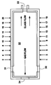
- glassmelting furnace 32 where glassmaking material is passed into the furnace through charger ports 30 and 31.
- the glassmaking materials pass through the furnace from left to right as indicated by the glass flow arrows and in doing so are melted by heat from combustion carried out by burners 1-20 which are shown in representative form by the arrows.
- the melted glass passes out from the furnace through throat passage 33.
- the combustion reaction gases flow above the glassmaking materials in the opposite direction as indicated by the gas flow arrow and out of furnace 32 through flue 34.
- a furnace similar to that illustrated in the Figure was operated with all twenty burners being high NOx burners of the type illustrated in U.S. Patent No. 5,267,850.
- the fuel used was natural gas and the oxidant used was a fluid comprising 93 mole percent oxygen.
- the burners generated NOx at the rate of 0.30 lb/million BTU.
- the NOx generation rate equilibrium value was 0.21 1b/million BTU.
- the NOx emissions were measured at the flue and found to be 1.43 lb NOx/ton glass.
- Burner numbers 1-12 were changed to low NOx burners using natural gas as fuel and a fluid comprising 93 mole percent oxygen as oxidant and the furnace was again operated to produce molten glass.
- the low NOx burners were operated in the manner described in U.S. Serial No. 153,505, filed November 17, 1993 and generated NOx at the rate of 0.067 1b/million BTU. Based on laboratory results of the operation of the two different burners, it was expected that the replacement of 12 of the 20 high NOx burners with low NOx burners would reduce the NOx emissions at the flue by 45 percent. However, when the invention was actually carried out, the measured NOx emissions at the flue were only 0.5 lb NOx/ton glass, a 65 percent reduction.
Landscapes
- Engineering & Computer Science (AREA)
- Chemical & Material Sciences (AREA)
- Combustion & Propulsion (AREA)
- Materials Engineering (AREA)
- Organic Chemistry (AREA)
- Mechanical Engineering (AREA)
- General Engineering & Computer Science (AREA)
- Treating Waste Gases (AREA)
Abstract
Description
- This invention relates generally to the operation of furnaces and more particularly to the reduction of nitrogen oxides (NOx) emitted from a furnace.
- Many industrial processes employ furnaces wherein fuel and oxidant are combusted to generate heat which is used to heat a charge within the furnace. Among such industrial processes one can name glassmaking wherein the charge is glassmaking materials or molten or solid glass, steelmaking wherein the charge is steel or iron and aluminum melting wherein the charge is aluminum ingots or scrap.
- Nitrogen oxides are a significant pollutant generated during combustion and it is desirable to reduce their generation in carrying out combustion. It is known that combustion may be carried out with reduced NOx generation by using technically pure oxygen or oxygen-enriched air as the oxidant as this reduces the amount of nitrogen provided to the combustion reaction on an equivalent oxygen basis. However, the use of an oxidant having a higher oxygen concentration than that of air causes the combustion reaction to run at a higher temperature and this higher temperature kinetically favors the formation of NOx.
- It is known that different burners and burner systems will, in operation, generate NOx at different rates. For example, all other things being equal, combustion using a concentric burner arrangement will generally result in greater NOx formation than will combustion using a staged burner arrangement. Accordingly, in a furnace employing a plurality of burners, one may reduce NOx emissions from the furnace by replacing one or more of the high NOx burners with low NOx burners. However, such a conversion is costly and it is desirable to reduce the number of burners in a multiburner furnace which must be converted from high NOx to low NOx.
- Accordingly, it is an object of this invention to provide a method for operating a furnace which can minimize the number of low NOx burners used for any particular target level of NOx emissions from the furnace.
- The above and other objects, which will become apparent to one skilled in the art upon a reading of this disclosure, are attained by:
- A method for operating a furnace to reduce the level of NOx emitted from the flue of the furnace comprising:
- (A) combusting fuel and oxidant in a first combustion reaction wherein NOx is generated within the furnace at a rate or value exceeding the equilibrium value;
- (B) combusting fuel and oxidant in a second combustion reaction wherein NOx is generated within the furnace at a rate or value lower than that of the first combustion reaction, said second combustion reaction occurring nearer to the flue than said first combustion reaction; and
- (C) passing NOx generated by said first and second combustion reactions out from the furnace through the flue.
- As used herein the term "flue" means a passage capable of passing furnace gases out from the furnace, generally to the ambient atmosphere.
- As used herein the term "equilibrium value" means the concentration of nitric oxide plus nitrogen dioxide that would result if the concentration of nitrogen and oxygen in the furnace combustion products were held at the furnace gas temperature for an infinite period of time. Those skilled in the art are familiar with how to calculate equilibrium values using published equilibrium constants.
- As used herein the term "high NOx burner" means a burner which carries out a combustion reaction wherein NOx is generated above the equilibrium value. Examples of high NOx burners can be found in U.S. Patent No. 5,267,850 and U.S. Patent No. 5,256,058.
- As used herein the term "low NOx burner" means a burner which carries out a combustion reaction wherein NOx is generated below that of a high NOx burner and can be generated below the equilibrium value. Examples of low NOx burners can be found in U.S. Patent No. 4,378,205, U.S. Patent No. 4,907,961 and U.S. Patent No. 5,209,656.
- As used herein the terms "nitrogen oxides" and "NOx" mean the sum of nitric oxide (NO) and nitrogen dioxide (NO₂).
- The sole Figure is a simplified plan view representation of one furnace which may be used in the practice of the invention.
- This invention comprises the recognition that the NOx level generated in a combustion reaction is not static within a furnace but rather is dynamic within the furnace and, furthermore, that the nonstatic condition is in the direction toward the equilibrium value. The longer the combustion reaction gases from a combustion reaction remain in a furnace, the closer to the NOx equilibrium value they will come prior to exiting the furnace through the flue. The rate at which the gases approach the equilibrium value depends on the temperature of the furnace. The invention achieves the best results when the furnace temperature exceeds 2700°F.
- In a multiburner furnace the level of NOx emitted from the flue may be disproportionately reduced by the practice of the invention over that which is achieved by the mere replacement of one or more high NOx burners with low NOx burners. If a low NOx burner is positioned in the furnace at a significant distance from the flue and it generates NOx levels below the equilibrium value, the furnace gases resulting from the combustion will have a long residence time within the furnace as they proceed toward the flue, and this long residence time will result in an increase in the level of NOx as the below equilibrium value of the NOx generated by the combustion dynamically progresses toward the equilibrium value. Moreover, if a high NOx burner is positioned in the furnace near the flue, the furnace gases resulting from the combustion will have a short residence time within the furnace which will not allow a significant NOx reduction. However, if a high NOx burner is positioned in the furnace at a significant distance from the flue, the furnace gases resulting from the combustion will have a long residence time within the furnace as they proceed toward the flue, and this long residence time will result in a decrease in the level of NOx as the above equilibrium value of the NOx generated by the combustion dynamically progresses toward the equilibrium value. The dynamic progression, either an increase or a decrease, toward the equilibrium value does not continue appreciably outside the furnace zone because it is the furnace conditions of heat, fluid flows and reactant concentrations which cause the dynamic progression toward equilibrium to take place.
- The fuel useful in the practice of this invention may be any gas or other fuel which contains combustibles which may combust in a furnace or combustion zone. Among such fuels one can name natural gas, coke oven gas, propane, methane, oil and pulverized coal.
- The oxidant useful in the practice of this invention is any fluid containing sufficient oxygen to combust with fuel in a furnace or combustion zone. The oxidant may be air. Preferably the oxidant is a fluid having an oxygen concentration of at least 30 volume percent oxygen, most preferably at least 90 volume percent oxygen. The oxidant may be technically pure oxygen having an oxygen concentration of 99.5 percent or more.
- The furnace which may be used in the practice of this invention is generally an industrial furnace. The invention will have particular utility in the operation of a glassmaking furnace due to the high temperatures involved. A furnace includes burner ports wherein a burner may be placed and wherein some of all of the combustion may take place.
- The invention will be described in greater detail with reference to the Figure and the following example and comparative example. The example is presented for illustrative purposes and is not intended to be limiting.
- Referring now to the Figure, there is shown in simplified
form glassmelting furnace 32 where glassmaking material is passed into the furnace throughcharger ports throat passage 33. The combustion reaction gases flow above the glassmaking materials in the opposite direction as indicated by the gas flow arrow and out offurnace 32 throughflue 34. - A furnace similar to that illustrated in the Figure was operated with all twenty burners being high NOx burners of the type illustrated in U.S. Patent No. 5,267,850. The fuel used was natural gas and the oxidant used was a fluid comprising 93 mole percent oxygen. The burners generated NOx at the rate of 0.30 lb/million BTU. The NOx generation rate equilibrium value was 0.21 1b/million BTU. The NOx emissions were measured at the flue and found to be 1.43 lb NOx/ton glass.
- Burner numbers 1-12 were changed to low NOx burners using natural gas as fuel and a fluid comprising 93 mole percent oxygen as oxidant and the furnace was again operated to produce molten glass. The low NOx burners were operated in the manner described in U.S. Serial No. 153,505, filed November 17, 1993 and generated NOx at the rate of 0.067 1b/million BTU. Based on laboratory results of the operation of the two different burners, it was expected that the replacement of 12 of the 20 high NOx burners with low NOx burners would reduce the NOx emissions at the flue by 45 percent. However, when the invention was actually carried out, the measured NOx emissions at the flue were only 0.5 lb NOx/ton glass, a 65 percent reduction.
- Heretofore it has been conventional practice to employ one type of burner throughout a multiburner furnace. If conditions required a burner changeover, typically all of the burners were changed. The invention employs an unconventional arrangement wherein two different burner types are used in a multiburner furnace. Moreover, by the practice of this invention, one can attain a greater degree of NOx reduction for any given level of burner conversion from high NOx to low NOx in the operation of a multiburner furnace than would otherwise be possible. Although the invention has been described in detail with reference to a certain preferred embodiment, those skilled in the art will recognize that there are other embodiments of the invention within the spirit and the scope of the claims.
Claims (8)
- A method for operating a furnace to reduce the level of NOx emitted from the flue of the furnace comprising:(A) combusting fuel and oxidant in a first combustion reaction wherein NOx is generated within the furnace at a value exceeding the equilibrium value;(B) combusting fuel and oxidant in a second combustion reaction wherein NOx is generated within the furnace at a value lower than that of the first combustion reaction, said second combustion reaction occurring nearer to the flue than said first combustion reaction; and(C) passing NOx generated by said first and second combustion reactions out from the furnace through the flue.
- The method of Claim 1 wherein NOx is generated in the second combustion reaction at a value lower than the equilibrium value.
- The method of Claim 1 wherein there is carried out a plurality of first reactions.
- The method of Claim 1 wherein there is carried out a plurality of second reactions.
- The method of Claim 1 wherein there is carried out a plurality of first reactions and a plurality of second reactions.
- The method of Claim 5 wherein all of the second reactions occur nearer to the flue than do any of the first reactions.
- The method of Claim 1 wherein the furnace is a glassmaking furnace.
- The method of Claim 1 wherein the temperature within the furnace exceeds 2700°F.
Applications Claiming Priority (2)
| Application Number | Priority Date | Filing Date | Title |
|---|---|---|---|
| US24540894A | 1994-05-18 | 1994-05-18 | |
| US245408 | 1994-05-18 |
Publications (3)
| Publication Number | Publication Date |
|---|---|
| EP0683357A2 true EP0683357A2 (en) | 1995-11-22 |
| EP0683357A3 EP0683357A3 (en) | 1996-09-18 |
| EP0683357B1 EP0683357B1 (en) | 2000-03-01 |
Family
ID=22926533
Family Applications (1)
| Application Number | Title | Priority Date | Filing Date |
|---|---|---|---|
| EP95107552A Expired - Lifetime EP0683357B1 (en) | 1994-05-18 | 1995-05-17 | Method for operating a furnace |
Country Status (10)
| Country | Link |
|---|---|
| US (1) | US5683238A (en) |
| EP (1) | EP0683357B1 (en) |
| JP (1) | JPH0842813A (en) |
| KR (1) | KR100219746B1 (en) |
| CN (1) | CN1131722C (en) |
| BR (1) | BR9502060A (en) |
| CA (1) | CA2149554C (en) |
| DE (1) | DE69515207T2 (en) |
| ES (1) | ES2142969T3 (en) |
| PT (1) | PT683357E (en) |
Cited By (1)
| Publication number | Priority date | Publication date | Assignee | Title |
|---|---|---|---|---|
| WO2002031407A1 (en) * | 2000-10-12 | 2002-04-18 | Asahi Glass Company, Limited | Method for reducing nitrogen oxides in combustion gas from combustion furnace |
Families Citing this family (11)
| Publication number | Priority date | Publication date | Assignee | Title |
|---|---|---|---|---|
| US6705117B2 (en) | 1999-08-16 | 2004-03-16 | The Boc Group, Inc. | Method of heating a glass melting furnace using a roof mounted, staged combustion oxygen-fuel burner |
| US6221127B1 (en) | 1999-11-10 | 2001-04-24 | Svedala Industries, Inc. | Method of pyroprocessing mineral ore material for reducing combustion NOx |
| US6290492B1 (en) | 2000-02-15 | 2001-09-18 | Air Products And Chemicals, Inc. | Method of reducing NOx emission from multi-zone reheat furnaces |
| US6745708B2 (en) * | 2001-12-19 | 2004-06-08 | Conocophillips Company | Method and apparatus for improving the efficiency of a combustion device |
| CN1313726C (en) * | 2004-06-10 | 2007-05-02 | 上海交通大学 | Seawave preventing cover on inlet and outlet of combustion engine for diver |
| US7833009B2 (en) * | 2004-09-10 | 2010-11-16 | Air Products And Chemicals, Inc. | Oxidant injection method |
| US7452400B2 (en) * | 2005-07-07 | 2008-11-18 | The North American Manufacturing Company, Ltd. | Method and apparatus for melting metal |
| US20100159409A1 (en) * | 2006-06-05 | 2010-06-24 | Richardson Andrew P | Non-centric oxy-fuel burner for glass melting systems |
| US20070281264A1 (en) * | 2006-06-05 | 2007-12-06 | Neil Simpson | Non-centric oxy-fuel burner for glass melting systems |
| US20080081301A1 (en) * | 2006-10-03 | 2008-04-03 | Hannum Mark C | Low NOx combustion |
| EP2415886A1 (en) * | 2010-08-04 | 2012-02-08 | L'air Liquide, Societe Anonyme Pour L'etude Et L'exploitation Des Procedes Georges Claude | Process for melting scrap metal |
Citations (5)
| Publication number | Priority date | Publication date | Assignee | Title |
|---|---|---|---|---|
| US4378205A (en) | 1980-04-10 | 1983-03-29 | Union Carbide Corporation | Oxygen aspirator burner and process for firing a furnace |
| US4907961A (en) | 1988-05-05 | 1990-03-13 | Union Carbide Corporation | Oxygen jet burner and combustion method |
| US5209656A (en) | 1991-08-29 | 1993-05-11 | Praxair Technology, Inc. | Combustion system for high velocity gas injection |
| US5256058A (en) | 1992-03-30 | 1993-10-26 | Combustion Tec, Inc. | Method and apparatus for oxy-fuel heating with lowered NOx in high temperature corrosive environments |
| US5267850A (en) | 1992-06-04 | 1993-12-07 | Praxair Technology, Inc. | Fuel jet burner |
Family Cites Families (18)
| Publication number | Priority date | Publication date | Assignee | Title |
|---|---|---|---|---|
| US3746498A (en) * | 1972-01-24 | 1973-07-17 | Combustion Eng | Reducing no{11 {11 emissions by additive injection |
| JPS5237611B2 (en) * | 1973-03-01 | 1977-09-24 | ||
| US4117075A (en) * | 1973-08-09 | 1978-09-26 | Agency Of Industrial Science & Technology | Method of combustion for depressing nitrogen oxide discharge |
| US3890084A (en) * | 1973-09-26 | 1975-06-17 | Coen Co | Method for reducing burner exhaust emissions |
| US4061487A (en) * | 1976-07-01 | 1977-12-06 | Union Carbide Corporation | Process for producing glass in a rotary furnace |
| JPS5623615A (en) * | 1979-08-06 | 1981-03-06 | Babcock Hitachi Kk | Burning method for low nox |
| US4427362A (en) * | 1980-08-14 | 1984-01-24 | Rockwell International Corporation | Combustion method |
| US4405587A (en) * | 1982-02-16 | 1983-09-20 | Mcgill Incorporated | Process for reduction of oxides of nitrogen |
| US4909728A (en) * | 1986-09-26 | 1990-03-20 | Matsushita Electric Industrial Co., Ltd. | Combustion apparatus |
| US4973346A (en) * | 1989-10-30 | 1990-11-27 | Union Carbide Corporation | Glassmelting method with reduced nox generation |
| US5154596A (en) * | 1990-09-07 | 1992-10-13 | John Zink Company, A Division Of Koch Engineering Company, Inc. | Methods and apparatus for burning fuel with low NOx formation |
| US5076779A (en) * | 1991-04-12 | 1991-12-31 | Union Carbide Industrial Gases Technology Corporation | Segregated zoning combustion |
| US5147438A (en) * | 1991-09-18 | 1992-09-15 | Union Carbide Industrial Gases Technology Corporation | Auxiliary oxygen burners technique in glass melting cross-fired regenerative furnaces |
| US5199866A (en) * | 1992-03-30 | 1993-04-06 | Air Products And Chemicals, Inc. | Adjustable momentum self-cooled oxy/fuel burner for heating in high temperature environments |
| DE4218702C2 (en) * | 1992-06-06 | 1994-03-31 | Sorg Gmbh & Co Kg | Regenerative melting tank with reduced NOx formation |
| US5242296A (en) * | 1992-12-08 | 1993-09-07 | Praxair Technology, Inc. | Hybrid oxidant combustion method |
| US5387100A (en) * | 1994-02-17 | 1995-02-07 | Praxair Technology, Inc. | Super off-stoichiometric combustion method |
| DE4416650A1 (en) * | 1994-05-11 | 1995-11-16 | Abb Management Ag | Combustion process for atmospheric combustion plants |
-
1995
- 1995-05-17 PT PT95107552T patent/PT683357E/en unknown
- 1995-05-17 KR KR1019950012662A patent/KR100219746B1/en not_active IP Right Cessation
- 1995-05-17 ES ES95107552T patent/ES2142969T3/en not_active Expired - Lifetime
- 1995-05-17 JP JP7141367A patent/JPH0842813A/en active Pending
- 1995-05-17 EP EP95107552A patent/EP0683357B1/en not_active Expired - Lifetime
- 1995-05-17 DE DE69515207T patent/DE69515207T2/en not_active Expired - Fee Related
- 1995-05-17 CN CN95106035A patent/CN1131722C/en not_active Expired - Fee Related
- 1995-05-17 CA CA002149554A patent/CA2149554C/en not_active Expired - Fee Related
- 1995-05-17 BR BR9502060A patent/BR9502060A/en not_active IP Right Cessation
-
1996
- 1996-04-29 US US08/639,682 patent/US5683238A/en not_active Expired - Fee Related
Patent Citations (5)
| Publication number | Priority date | Publication date | Assignee | Title |
|---|---|---|---|---|
| US4378205A (en) | 1980-04-10 | 1983-03-29 | Union Carbide Corporation | Oxygen aspirator burner and process for firing a furnace |
| US4907961A (en) | 1988-05-05 | 1990-03-13 | Union Carbide Corporation | Oxygen jet burner and combustion method |
| US5209656A (en) | 1991-08-29 | 1993-05-11 | Praxair Technology, Inc. | Combustion system for high velocity gas injection |
| US5256058A (en) | 1992-03-30 | 1993-10-26 | Combustion Tec, Inc. | Method and apparatus for oxy-fuel heating with lowered NOx in high temperature corrosive environments |
| US5267850A (en) | 1992-06-04 | 1993-12-07 | Praxair Technology, Inc. | Fuel jet burner |
Cited By (4)
| Publication number | Priority date | Publication date | Assignee | Title |
|---|---|---|---|---|
| WO2002031407A1 (en) * | 2000-10-12 | 2002-04-18 | Asahi Glass Company, Limited | Method for reducing nitrogen oxides in combustion gas from combustion furnace |
| EP1326049A1 (en) * | 2000-10-12 | 2003-07-09 | Asahi Glass Company Ltd. | Method for reducing nitrogen oxides in combustion gas from combustion furnace |
| US6939125B2 (en) | 2000-10-12 | 2005-09-06 | Asahi Glass Company, Limited | Method for reducing nitrogen oxides in combustion gas from combustion furnace |
| EP1326049A4 (en) * | 2000-10-12 | 2005-10-26 | Asahi Glass Co Ltd | Method for reducing nitrogen oxides in combustion gas from combustion furnace |
Also Published As
| Publication number | Publication date |
|---|---|
| DE69515207T2 (en) | 2000-08-24 |
| CN1120969A (en) | 1996-04-24 |
| KR950031945A (en) | 1995-12-20 |
| CA2149554C (en) | 1999-11-30 |
| EP0683357A3 (en) | 1996-09-18 |
| DE69515207D1 (en) | 2000-04-06 |
| BR9502060A (en) | 1995-12-19 |
| PT683357E (en) | 2000-06-30 |
| KR100219746B1 (en) | 1999-09-01 |
| JPH0842813A (en) | 1996-02-16 |
| EP0683357B1 (en) | 2000-03-01 |
| ES2142969T3 (en) | 2000-05-01 |
| CA2149554A1 (en) | 1995-11-19 |
| CN1131722C (en) | 2003-12-24 |
| US5683238A (en) | 1997-11-04 |
Similar Documents
| Publication | Publication Date | Title |
|---|---|---|
| EP0601274B1 (en) | Hybrid oxidant combustion method | |
| US5755818A (en) | Staged combustion method | |
| Normann et al. | High-temperature reduction of nitrogen oxides in oxy-fuel combustion | |
| EP0590572B1 (en) | Thermal nozzle combustion method | |
| EP0344784B1 (en) | Low nox high efficiency combustion process | |
| EP0759412B1 (en) | Flat glass furnaces | |
| US5924858A (en) | Staged combustion method | |
| US5417731A (en) | Method of heating a charge, including injecting secondary oxidant into the output port | |
| CA2149554C (en) | Method for operating a furnace | |
| EP0653590A1 (en) | Method for deeply staged combustion | |
| EP0922772B1 (en) | Hot oxygen blast furnace injection system | |
| EP0541105A2 (en) | Recirculation and plug flow combustion method | |
| EP0640794B2 (en) | Combustion using argon with oxygen | |
| EP1990322A1 (en) | Solid fuel combustion for industrial melting with a slagging combustor | |
| EP0643019B1 (en) | Method for processing niter-containing glassmaking materials | |
| US5823124A (en) | Method and system to reduced NOx and fuel emissions from a furnace | |
| EP0748981A2 (en) | Staged combustion with reduced generation of both nitrogen oxides and carbon monoxide | |
| Miller et al. | Nox abatement by Fuel-Lean reburning: Laboratory combustor and Pilot-Scale package boiler results | |
| SU1673784A1 (en) | Burning of fuel at thermal power station | |
| SU1755006A1 (en) | Method of combined burning of natural, coke, blast-furnace cages and pulverized fuel |
Legal Events
| Date | Code | Title | Description |
|---|---|---|---|
| PUAI | Public reference made under article 153(3) epc to a published international application that has entered the european phase |
Free format text: ORIGINAL CODE: 0009012 |
|
| AK | Designated contracting states |
Kind code of ref document: A2 Designated state(s): BE DE ES FR IT NL PT |
|
| PUAL | Search report despatched |
Free format text: ORIGINAL CODE: 0009013 |
|
| AK | Designated contracting states |
Kind code of ref document: A3 Designated state(s): BE DE ES FR IT NL PT |
|
| 17P | Request for examination filed |
Effective date: 19961018 |
|
| 17Q | First examination report despatched |
Effective date: 19980609 |
|
| GRAG | Despatch of communication of intention to grant |
Free format text: ORIGINAL CODE: EPIDOS AGRA |
|
| GRAG | Despatch of communication of intention to grant |
Free format text: ORIGINAL CODE: EPIDOS AGRA |
|
| GRAH | Despatch of communication of intention to grant a patent |
Free format text: ORIGINAL CODE: EPIDOS IGRA |
|
| GRAH | Despatch of communication of intention to grant a patent |
Free format text: ORIGINAL CODE: EPIDOS IGRA |
|
| GRAA | (expected) grant |
Free format text: ORIGINAL CODE: 0009210 |
|
| ITF | It: translation for a ep patent filed | ||
| AK | Designated contracting states |
Kind code of ref document: B1 Designated state(s): BE DE ES FR IT NL PT |
|
| REF | Corresponds to: |
Ref document number: 69515207 Country of ref document: DE Date of ref document: 20000406 |
|
| ET | Fr: translation filed | ||
| REG | Reference to a national code |
Ref country code: ES Ref legal event code: FG2A Ref document number: 2142969 Country of ref document: ES Kind code of ref document: T3 |
|
| REG | Reference to a national code |
Ref country code: PT Ref legal event code: SC4A Free format text: AVAILABILITY OF NATIONAL TRANSLATION Effective date: 20000314 |
|
| PLBE | No opposition filed within time limit |
Free format text: ORIGINAL CODE: 0009261 |
|
| STAA | Information on the status of an ep patent application or granted ep patent |
Free format text: STATUS: NO OPPOSITION FILED WITHIN TIME LIMIT |
|
| 26N | No opposition filed | ||
| PGFP | Annual fee paid to national office [announced via postgrant information from national office to epo] |
Ref country code: PT Payment date: 20040506 Year of fee payment: 10 |
|
| PG25 | Lapsed in a contracting state [announced via postgrant information from national office to epo] |
Ref country code: PT Free format text: LAPSE BECAUSE OF NON-PAYMENT OF DUE FEES Effective date: 20051117 |
|
| PGFP | Annual fee paid to national office [announced via postgrant information from national office to epo] |
Ref country code: ES Payment date: 20080526 Year of fee payment: 14 |
|
| PGFP | Annual fee paid to national office [announced via postgrant information from national office to epo] |
Ref country code: BE Payment date: 20080624 Year of fee payment: 14 |
|
| PGFP | Annual fee paid to national office [announced via postgrant information from national office to epo] |
Ref country code: NL Payment date: 20080524 Year of fee payment: 14 Ref country code: DE Payment date: 20080630 Year of fee payment: 14 |
|
| PGFP | Annual fee paid to national office [announced via postgrant information from national office to epo] |
Ref country code: IT Payment date: 20080528 Year of fee payment: 14 |
|
| BERE | Be: lapsed |
Owner name: *PRAXAIR TECHNOLOGY INC. Effective date: 20090531 |
|
| NLV4 | Nl: lapsed or anulled due to non-payment of the annual fee |
Effective date: 20091201 |
|
| PG25 | Lapsed in a contracting state [announced via postgrant information from national office to epo] |
Ref country code: NL Free format text: LAPSE BECAUSE OF NON-PAYMENT OF DUE FEES Effective date: 20091201 |
|
| REG | Reference to a national code |
Ref country code: FR Ref legal event code: ST Effective date: 20100129 |
|
| PG25 | Lapsed in a contracting state [announced via postgrant information from national office to epo] |
Ref country code: FR Free format text: LAPSE BECAUSE OF NON-PAYMENT OF DUE FEES Effective date: 20090602 |
|
| PGFP | Annual fee paid to national office [announced via postgrant information from national office to epo] |
Ref country code: FR Payment date: 20080519 Year of fee payment: 14 |
|
| PG25 | Lapsed in a contracting state [announced via postgrant information from national office to epo] |
Ref country code: DE Free format text: LAPSE BECAUSE OF NON-PAYMENT OF DUE FEES Effective date: 20091201 Ref country code: BE Free format text: LAPSE BECAUSE OF NON-PAYMENT OF DUE FEES Effective date: 20090531 |
|
| REG | Reference to a national code |
Ref country code: ES Ref legal event code: FD2A Effective date: 20090518 |
|
| PG25 | Lapsed in a contracting state [announced via postgrant information from national office to epo] |
Ref country code: ES Free format text: LAPSE BECAUSE OF NON-PAYMENT OF DUE FEES Effective date: 20090518 |
|
| PG25 | Lapsed in a contracting state [announced via postgrant information from national office to epo] |
Ref country code: IT Free format text: LAPSE BECAUSE OF NON-PAYMENT OF DUE FEES Effective date: 20090517 |