EP0683064A1 - Sliding window for vehicle - Google Patents
Sliding window for vehicle Download PDFInfo
- Publication number
- EP0683064A1 EP0683064A1 EP95105078A EP95105078A EP0683064A1 EP 0683064 A1 EP0683064 A1 EP 0683064A1 EP 95105078 A EP95105078 A EP 95105078A EP 95105078 A EP95105078 A EP 95105078A EP 0683064 A1 EP0683064 A1 EP 0683064A1
- Authority
- EP
- European Patent Office
- Prior art keywords
- vehicle
- pane
- window according
- sliding
- sliding window
- Prior art date
- Legal status (The legal status is an assumption and is not a legal conclusion. Google has not performed a legal analysis and makes no representation as to the accuracy of the status listed.)
- Granted
Links
Images


Classifications
-
- E—FIXED CONSTRUCTIONS
- E05—LOCKS; KEYS; WINDOW OR DOOR FITTINGS; SAFES
- E05D—HINGES OR SUSPENSION DEVICES FOR DOORS, WINDOWS OR WINGS
- E05D15/00—Suspension arrangements for wings
- E05D15/06—Suspension arrangements for wings for wings sliding horizontally more or less in their own plane
- E05D15/10—Suspension arrangements for wings for wings sliding horizontally more or less in their own plane movable out of one plane into a second parallel plane
- E05D15/1065—Suspension arrangements for wings for wings sliding horizontally more or less in their own plane movable out of one plane into a second parallel plane with transversely moving track
- E05D15/1081—Suspension arrangements for wings for wings sliding horizontally more or less in their own plane movable out of one plane into a second parallel plane with transversely moving track specially adapted for vehicles
-
- B—PERFORMING OPERATIONS; TRANSPORTING
- B60—VEHICLES IN GENERAL
- B60J—WINDOWS, WINDSCREENS, NON-FIXED ROOFS, DOORS, OR SIMILAR DEVICES FOR VEHICLES; REMOVABLE EXTERNAL PROTECTIVE COVERINGS SPECIALLY ADAPTED FOR VEHICLES
- B60J1/00—Windows; Windscreens; Accessories therefor
- B60J1/08—Windows; Windscreens; Accessories therefor arranged at vehicle sides
- B60J1/12—Windows; Windscreens; Accessories therefor arranged at vehicle sides adjustable
- B60J1/16—Windows; Windscreens; Accessories therefor arranged at vehicle sides adjustable slidable
-
- E—FIXED CONSTRUCTIONS
- E05—LOCKS; KEYS; WINDOW OR DOOR FITTINGS; SAFES
- E05D—HINGES OR SUSPENSION DEVICES FOR DOORS, WINDOWS OR WINGS
- E05D15/00—Suspension arrangements for wings
- E05D15/56—Suspension arrangements for wings with successive different movements
- E05D15/58—Suspension arrangements for wings with successive different movements with both swinging and sliding movements
-
- E—FIXED CONSTRUCTIONS
- E05—LOCKS; KEYS; WINDOW OR DOOR FITTINGS; SAFES
- E05D—HINGES OR SUSPENSION DEVICES FOR DOORS, WINDOWS OR WINGS
- E05D15/00—Suspension arrangements for wings
- E05D15/06—Suspension arrangements for wings for wings sliding horizontally more or less in their own plane
- E05D15/10—Suspension arrangements for wings for wings sliding horizontally more or less in their own plane movable out of one plane into a second parallel plane
- E05D15/1065—Suspension arrangements for wings for wings sliding horizontally more or less in their own plane movable out of one plane into a second parallel plane with transversely moving track
- E05D2015/1071—Suspension arrangements for wings for wings sliding horizontally more or less in their own plane movable out of one plane into a second parallel plane with transversely moving track the track being directly linked to the fixed frame, e.g. slidingly
- E05D2015/1078—Suspension arrangements for wings for wings sliding horizontally more or less in their own plane movable out of one plane into a second parallel plane with transversely moving track the track being directly linked to the fixed frame, e.g. slidingly swinging or rotating in a horizontal plane
-
- E—FIXED CONSTRUCTIONS
- E05—LOCKS; KEYS; WINDOW OR DOOR FITTINGS; SAFES
- E05D—HINGES OR SUSPENSION DEVICES FOR DOORS, WINDOWS OR WINGS
- E05D15/00—Suspension arrangements for wings
- E05D15/06—Suspension arrangements for wings for wings sliding horizontally more or less in their own plane
- E05D15/10—Suspension arrangements for wings for wings sliding horizontally more or less in their own plane movable out of one plane into a second parallel plane
- E05D15/1065—Suspension arrangements for wings for wings sliding horizontally more or less in their own plane movable out of one plane into a second parallel plane with transversely moving track
- E05D2015/1084—Suspension arrangements for wings for wings sliding horizontally more or less in their own plane movable out of one plane into a second parallel plane with transversely moving track the carriage being directly linked to the fixed frame, e.g. slidingly
-
- E—FIXED CONSTRUCTIONS
- E05—LOCKS; KEYS; WINDOW OR DOOR FITTINGS; SAFES
- E05Y—INDEXING SCHEME RELATING TO HINGES OR OTHER SUSPENSION DEVICES FOR DOORS, WINDOWS OR WINGS AND DEVICES FOR MOVING WINGS INTO OPEN OR CLOSED POSITION, CHECKS FOR WINGS AND WING FITTINGS NOT OTHERWISE PROVIDED FOR, CONCERNED WITH THE FUNCTIONING OF THE WING
- E05Y2900/00—Application of doors, windows, wings or fittings thereof
- E05Y2900/50—Application of doors, windows, wings or fittings thereof for vehicles
- E05Y2900/53—Application of doors, windows, wings or fittings thereof for vehicles characterised by the type of wing
- E05Y2900/55—Windows
Definitions
- the invention relates to a vehicle sliding window that can be inserted into an opening in side parts of a vehicle body and / or in the vehicle doors.
- opening windows In vehicles, opening windows are known which can be pivoted about a vertical axis or about an axis slightly inclined to the vertical. These windows are often used when it is a two-door car.
- the pivot axis of such opening windows lies in the area of the front edge of the windows when viewed in the forward direction of travel.
- a suitable opening fitting is provided on the opposite rear edge in the direction of travel in order to open the window to the outside.
- Windows are also known, the panes of which can be moved up and down in the vertical direction by means of a window lift drive. Such windows are designed for the doors of a vehicle. Windows of this type are usually used in multi-door passenger cars. In the case of passenger cars, these options have long been proven individually or in combination.
- the invention has for its object to provide a vehicle sliding window that offers the possibility in a structurally simple manner that either a ventilation slot such as the conventional opening windows or a ventilation opening can be formed, the level of the glass panes in the closed state approximately with the level of The outer skin of the body collapses in the window area.
- the vehicle sliding window has two panes which are in alignment in the closed position, that the front pane in the forward direction of travel can be tilted outwards about a vertical or slightly inclined axis relative to the vertical, and that the rear pane is displaceably arranged in the direction of travel so that in the open position it is laterally next to the inside of the issued front pane.
- the vehicle sliding window has two panes aligned in the closed position, that the front pane in the forward driving direction can be tilted outwards about a vertical or slightly inclined axis relative to the vertical, while the rear pane in the direction of travel is arranged to be stationary , and that the front disc is arranged so that it is at least partially laterally adjacent to the outside of the rear stationary disc in the open position.
- the vehicle sliding window is symmetrically or asymmetrically divided by the front and rear window in the closed position of the windows, with the asymmetrical division the length of the rear window in the forward direction is less than the front window.
- the lengths of the front pane to the rear pane are expediently in a ratio of approximately 2: 1. This results in particularly favorable installation conditions when the panes are next to each other. So that the vehicle sliding window can be used as a prefabricated unit in an opening in the body or the door, provision is made for the panes to be arranged on an outer frame which can be inserted into the opening of the body or the door.
- this frame is expediently made of profile bars of suitable cross-section, so that these bars can simultaneously be used as a guide for the displacement of the respective pane.
- the vertical profile spar, which is at the front in the direction of travel, of an additionally provided display frame is mounted in at least one bearing sleeve.
- the central longitudinal axis of this bearing sleeve then forms the pivot axis.
- a profiled rail which can preferably be moved back and forth on the lower horizontal profiled rail, is provided as the pane holder. This keeps the number of components to a minimum, so that the vehicle sliding window as a whole is very compact.
- a guide rail is expediently assigned to the upper and lower edge of the displaceable disk.
- FIGS. 2 and 3 A first embodiment of such a vehicle sliding window is shown in schematic form in FIGS. 2 and 3.
- a base frame 3, which is angular in cross section, is fixed to the side body parts.
- the vehicle sliding window 2 comprises a front pane 4 and a rear pane 5.
- the window is drawn in the closed position.
- the two disks 4, 5 are flush with one another in one plane.
- the forward direction of travel of the MPV 1 is indicated by the arrow A in FIG. 2.
- the front disc 4 is can be pivoted about a front vertical axis 6 and can thus be opened about this axis. This position is shown in the upper illustration.
- the pivoting movement is indicated in FIG. 2 by the double arrow B.
- the pane 4 On the side opposite to the axis of rotation 6, the pane 4 is equipped with an opening fitting designated as a whole as 7, which can be actuated from inside the vehicle.
- the opening fitting 7 can be moved on a guide rod 8.
- the opening fitting 7 is moved towards the axis 6.
- the rear disc 5 is also slidable on the guide rod 8. For this purpose, it is provided with bearing blocks 9 on the inside.
- the length of the front disc 4 is approximately twice as long as the length of the rear disc 5.
- the disc dimensions can of course also have a different relationship to one another. This makes it possible that after the front disk 4 has been raised, the rear disk 5 can be moved in the direction of the axis 6 to such an extent that the two rear ends of the disks 4, 5 stand side by side at the same height. This creates a ventilation opening that is the size of the rear disc 5 corresponds. It is evident from FIG. 2 that in this example only the front pane 4 can perform an opening movement in order to form a ventilation slot of relatively small width, while the rear pane 5 can be moved back and forth in the direction of arrow C.
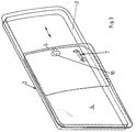
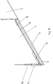
- FIG. 3 shows a perspective view of the representation according to FIG. 2 with the vehicle sliding window 2 open in accordance with FIG. the upper representation in Figure 2.
- the guide rod 8 and the bearing blocks 9 are not shown in Fig. 3.
- FIGS. 4-8 show a second embodiment of the vehicle sliding window 2 according to the invention.
- This vehicle sliding window can also be divided asymmetrically in the shape 10, so that the length of the front pane 4 is twice or approximately twice as large as the length of the rear pane 5.
- the front pane 4 can be opened by means of an opening fitting 7.
- the rear window 5 is immovably attached to the body.
- the guide rod 8, which can also be part of a frame made of round rods, follows the opening movement of the front pane 4. There is one on the lower, possibly also on the upper edge of the pane 4 Guide rail 11 attached.
- the guide rail 11 is guided in a stationary guide rail holder 12.
- FIG. 4 shows the closed position of the two disks 4 and 5. In this position, the two disks are again in alignment with one another.
- the front pane 4 is flipped outwards, so that the two panes 4, 5 are at an angle to one another.
- a push handle 10 is in turn arranged to move the front disc 4 against the forward driving direction to the rear, thereby forming a ventilation opening.
- FIG. 5 shows the deployed position of the pane 4, while FIG. 6 shows the open position, in which the rear region of the front pane 4 is offset outwards relative to the rear pane 5.
- the rear disc 5 is gem in the embodiment. 4-8 stationary, i.e. it cannot be issued or postponed.
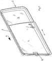
- Figures 7 u. 8 show the vehicle sliding window 2 of the above-described embodiment in a perspective view.
- Figure 7 shows the position shown
- Figure 8 shows the open position.
- the guide rod 8 is not shown.
- the direction of travel is indicated by arrow A. It can be seen from FIG. 8 that the size of the opening corresponds approximately to the size of the rear stationary disk 5.
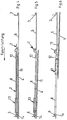
- FIGS. 9-11 show the complete front pane 4 with the associated fitting parts.
- the disc holder 13 consists of the two outer linear bushings 13 a and the intermediate receiving bush 13 b.
- FIG. 10 shows that the disc holder 13 is slidable on the guide rod 8.
- the guide rail holder 12 is arranged in the rear region of the front disk 4.
- FIG. 10 shows that the guide rail 11 is fixed on the edge of the front disk 4 in a manner that is not explained in detail.
- the guide rod 8 can be part of a frame, the front vertical spar being identified by the reference number 8 a.
- a bearing sleeve 14 is placed, which is attached to the base frame 3 (Fig. 4 to 6).
- the central axis 6 of the bearing sleeve 14 is the pivot axis for the opening movement of the front disk 4.
- FIG. 11 shows how the front pane 4 can be pushed laterally next to the rear stationary pane 5.
- the guide rail holder forms a stop for the sliding movement, since the disc holder 13 strikes against it.
- the respective discs 4 and 5 are closed in the reverse order.
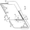
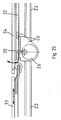
- FIGS. 12-18 show a further embodiment for a sliding and opening mechanism in detail. Since this is a variant which is preferably used in practice, it is explained in more detail below. Since the mechanical functions largely correspond to the other exemplary embodiments, what has been said here also applies to the other variants.
- the opening mechanism comprises a vertical axis 20, which is supported with its lower end in a mounting rail 21.
- the rear pane 33 which is in the direction of travel, is glued to the support rail 21 at several points or fastened in another suitable manner.
- the support rail 21 is placed on the lower horizontal beam 22 so that it can slide freely on this.
- the profile spar 22 simultaneously forms the lower part of the support frame 3.
- the upper corresponding profile spar of the frame 3 is designated by 23.
- the lateral vertical bars of the frame bear the reference numbers 24 and 25.
- the profile frame is screwed onto the edge of the body cut-out by means of screws 26 '.
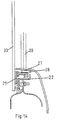
- the vertical axis 20, which can be rotated at its upper end by means of a suitable handle, not shown, has at its lower end a nose 26, into which a driving pin 27 is inserted, which, when the axis 20 is rotated about its virtual axis, from the Nose 26 is taken eccentrically.
- the driving pin 27 engages the end of a link lever 28, which forms the actual opening lever and is coupled at its other end to a guide pin 29, which in turn is fastened to the mounting rail 21 and projects upwards so that it engages in a groove 30 engages, which is located in the rear part of the deployment lever 28.
- the end of the deployment lever 28 assigned to the guide pin 29 has a sliding shoe 31 which slides in a profile rail 32 to which the front opening window 34 is glued in the forward direction of travel.
- the slide shoe 31 is connected by a pin 35 to the associated end of the deployment lever 28.
- the deployment movement of the disc 34 is achieved by the axis 20 z. B. is rotated by hand about its virtual axis so that the driving lever 27 of the opening lever 28 and thus inevitably the slide shoe 31 attached to it is moved in the direction of arrow 36 (Fig. 16).
- the deployment lever 28 slides along the guide pin 29 with the inner walls of the groove 30 which is adapted by means of a suitable path curvature and raises the deployment disk 34.
- This opening position is shown in FIG. 15.
- the sliding window 33 in the direction of travel can be moved in the direction of arrow 37 (FIGS. 12, 15) using a handle (not shown) with its associated structural and functional parts 20, 21 and 24 to 29 and 31.
- the display disk 34 is continuously shown.
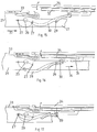
- FIG. 18 shows an embodiment for an opening mechanism in which, instead of the opening lever 28 in FIGS. 12-17, a modified opening lever 38 is provided, which with its end facing the opening disk 34 is articulated on a slide shoe 39 which has a groove 30 ' in which a pin 41 slides, which has the function of the guide pin 29 from FIG. 13. Otherwise, the movement sequences between the variant according to FIG. 13 and the embodiment according to FIG. 18 are corresponding. Insofar as the same parts are used, the reference symbols correspond to those according to FIG. 13.
- FIG. 20 shows a partially sectioned top view of the embodiment of FIG. 19.
Abstract
Description
Die Erfindung betrifft ein Fahrzeugschiebefenster, das in eine Öffnung von Seitenteilen einer Fahrzeugkarosserie und / oder in die Fahrzeugtüren einsetzbar ist.The invention relates to a vehicle sliding window that can be inserted into an opening in side parts of a vehicle body and / or in the vehicle doors.
Bei Fahrzeugen sind Ausstellfenster bekannt, die um eine vertikale oder um eine leicht gegen die Vertikale geneigte Achse verschwenkbar sind. Diese Fenster werden vielfach dann eingesetzt, wenn es sich um einen zweitürigen Personenkraftwagen handelt. Die Schwenkachse Solcher Ausstellfenster liegt im Bereich der in Vorwärtsfahrtrichtung gesehen vorderen Kante der Fenster. An der gegenüberliegenden, in Fahrtrichtung hinteren Kante ist ein geeigneter Ausstellbeschlag vorgesehen, um das Fenster nach außen auszustellen. Auch sind Fenster bekannt, deren Scheiben mittels eines Fensterheberantriebes in vertikaler Richtung auf- und abbewegbar sind. Solche Fenster sind für die Türen eines Fahrzeugs ausgelegt. Fenster dieser Art werden üblicherweise bei mehrtürigen Personenkraftwagen eingesetzt. Bei Personenkraftwagen haben sich diese Möglichkeiten einzeln oder in Kombination seit langem bewährt.In vehicles, opening windows are known which can be pivoted about a vertical axis or about an axis slightly inclined to the vertical. These windows are often used when it is a two-door car. The pivot axis of such opening windows lies in the area of the front edge of the windows when viewed in the forward direction of travel. A suitable opening fitting is provided on the opposite rear edge in the direction of travel in order to open the window to the outside. Windows are also known, the panes of which can be moved up and down in the vertical direction by means of a window lift drive. Such windows are designed for the doors of a vehicle. Windows of this type are usually used in multi-door passenger cars. In the case of passenger cars, these options have long been proven individually or in combination.
Bei Omnibussen ist es außerdem bekannt, den oberen Teil der Verglasung als Schiebeelemente auszubilden, um den Innenraum zu belüften. Von dieser Möglichkeiten wird wegen der entstehenden Zugluft jedoch von den Fahrzeuginsassen weniger Gebrauch gemacht.In the case of buses, it is also known to design the upper part of the glazing as sliding elements in order to ventilate the interior. Because of these possibilities however, the resulting drafts made less use of the vehicle occupants.
In neuerer Zeit sind sogenannte Großraumlimousinen verstärkt auf den Markt gekommen, die im Gegensatz zum normalen PKW mit Vorder- und Rücksitzen über mehrere hintereinander angeordnete Sitzreihen verfügen. Da der vordere Raum für den Fahrer und den Beifahrer auch häufig von der hinteren Zelle getrennt ist, muß dafür Sorge getragen werden, daß auch dieser Raum ausreichend belüftet werden kann. Dies ist mit den herkömmlichen zuvor beschriebenen Fenstern nicht möglich.In recent times, so-called people carriers have increasingly come onto the market, which, in contrast to normal cars with front and rear seats, have several rows of seats arranged one behind the other. Since the front space for the driver and front passenger is often separated from the rear cell, care must be taken to ensure that this space can also be adequately ventilated. This is not possible with the conventional windows described above.
Der Erfindung liegt die Aufgabe zugrunde, ein Fahrzeugschiebefenster zu schaffen, das in konstruktiv einfacher Weise die Möglichkeit bietet, daß wahlweise entweder ein Lüftungsschlitz wie den herkömmlichen Ausstellfenstern oder eine Lüftungsöffnung gebildet werden kann, wobei die Ebene der Glasscheiben in geschlossenem Zustand etwa mit der Ebene der Außenhaut der Karosserie im Fensterbereich zusammenfällt.The invention has for its object to provide a vehicle sliding window that offers the possibility in a structurally simple manner that either a ventilation slot such as the conventional opening windows or a ventilation opening can be formed, the level of the glass panes in the closed state approximately with the level of The outer skin of the body collapses in the window area.
Diese Aufgabe wird nach einem ersten Vorschlag der Erfindung gelöst, indem das Fahrzeugschiebefenster zwei in der Schließlage zueinander fluchtend stehende Scheiben aufweist, daß die in Vorwärtsfahrtrichtung vordere Scheibe um eine vertikale oder leicht gegen die Vertikale geneigte Achse nach außen ausstellbar ist, und daß die in Fahrtrichtung hintere Scheibe derart verschiebbar angeordnet ist, daß sie in der Offenstellung seitlich neben der Innenseite der ausgestellten vorderen Scheibe steht.This object is achieved according to a first proposal of the invention in that the vehicle sliding window has two panes which are in alignment in the closed position, that the front pane in the forward direction of travel can be tilted outwards about a vertical or slightly inclined axis relative to the vertical, and that the rear pane is displaceably arranged in the direction of travel so that in the open position it is laterally next to the inside of the issued front pane.
Nach einem zweiten Lösungsvorschlag ist vorgesehen, daß das Fahrzeugschiebefenster zwei in der Schließlage zueinander fluchtend stehende Scheiben aufweist, daß die in Vorwärtsfahrtrichtung vordere Scheibe um eine vertikale oder leicht gegen die Vertikale geneigte Achse nach außen ausstellbar ist, während die in Fahrtrichtung hintere Scheibe ortsfest angeordnet ist, und daß die vordere Scheibe derart verschiebbar angeordnet ist, daß sie in der Offenstellung zumindest bereichsweise seitlich neben der Außenseite der hinteren ortsfesten Scheibe steht.According to a second proposed solution, it is provided that the vehicle sliding window has two panes aligned in the closed position, that the front pane in the forward driving direction can be tilted outwards about a vertical or slightly inclined axis relative to the vertical, while the rear pane in the direction of travel is arranged to be stationary , and that the front disc is arranged so that it is at least partially laterally adjacent to the outside of the rear stationary disc in the open position.
Durch diese beiden aufgezeigten Lösungen nach der Erfindung wird die Möglichkeit geschaffen, daß die Fahrzeugscheiben nicht nur ausgestellt werden, sondern darüber hinaus, wenn das nicht ausreicht, auch zur Bildung einer zweiten Lüftungsöffnung verschoben werden können. Dabei ist es unbedeutend, ob wie bei dem ersten Lösungsvorschlag die in Vorwärtsfahrtrichtung hintere Scheibe seitlich neben die vordere, ausgestellte Scheibe geschoben werden kann,oder ob die vordere Scheibe so verschoben wird, daß sie seitlich neben der Außenseite der hinteren ortsfesten Scheibe steht. Welche dieser Möglichkeiten gewählt wird, ist fahrzeugtypabhängig und richtet sich danach, wie die gebildete Lüftungsöffnung zu den Sitzen des Fahrzeugs eingestellt sein soll. Es ist natürlich auch möglich, für die eine Fahrzeugseite die eine Lösung und für die andere Seite die andere Lösung zu wählen. Dabei kann das Fenster so flach ausgebildet werden, daß es innerhalb der äußeren Ebene der Karosserieöffnung für das Fenster liegt oder mit dieser fluchtet.These two indicated solutions according to the invention create the possibility that the vehicle windows are not only displayed, but also, if that is not sufficient, can also be moved to form a second ventilation opening. It is irrelevant whether, as in the first solution, the rear window in the forward direction can be pushed sideways next to the front, flared window, or whether the front window is moved so that it is laterally next to the outside of the rear stationary window. Which of these options is selected, depends on the vehicle type and depends on how the ventilation opening formed should be adjusted to the seats of the vehicle. It is of course also possible to choose one solution for one side of the vehicle and the other for the other side. The window can be made so flat that it lies within the outer plane of the body opening for the window or is flush with it.
In weiterer Ausgestaltung des Gegenstandes der Erfindung ist vorgesehen, daß das Fahrzeugschiebefenster durch die vordere und hintere Scheibe in der Schließlage der Scheiben symmetrisch oder asymmetrisch geteilt ist, wobei bei der asymmetrischen Teilung die Länge der in Vorwärtsfahrtrichtung hinteren Scheibe geringer ist als die vordere Scheibe. Dadurch läßt sich die Größe der Lüftungsöffnung in einfachster Weise variieren. Zweckmäßigerweise stehen bei der asymmetrischen Teilung des Schiebefensters die Längen der vorderen Scheibe zur hinteren Scheibe in einem Verhältnis von ca. 2:1. Dadurch ergeben sich konstruktiv besonders günstige Einbauverhältnisse, wenn die Scheiben nebeneinander stehen. Damit das Fahrzeugschiebefenster als vorgefertigte Einheit in eine Öffnung der Karosserie oder der Tür eingesetzt werden kann, ist vorgesehen, die Scheiben an einem in die Öffnung der Karosserie oder der Tür einsetzbaren äußeren Rahmen anzuordnen. Nach einem besonderen Ausführungsbeispiel besteht dieser Rahmen zweckmäßig aus Profilstäben geeigneten Querschnitts, so daß diese Stäbe gleichzeitig als Führung für die Verschiebung der jeweiligen Scheibe genutzt werden können. Damit beim Ausstellen der Scheibe der sich bildende Lüftungsschlitz in Vorwärtsfahrtrichtung hinten liegt, kann bei einer anderen Ausführungsform zweckmäßig vorgesehen sein, daß der in Fahrtrichtung vordere, vertikale Profilholm eines zusätzlich vorgesehenen Ausstellrahmens in wenigstens einer Lagerhülse gelagert ist. Die Mittellängsachse dieser Lagerhülse bildet dann die Schwenkachse. Zur einfachen und funktionssicheren Verschiebung der jeweiligen Scheibe ist vorgesehen, daß als Scheibenaufnahme eine vorzugsweise auf dem unteren horizontalen Profilholm hin und her verschiebbare Profilschiene vorgesehen ist. Dadurch wird die Anzahl der Bauteile auf einem Minimum gehalten, so daß das Fahrzeugschiebefenster als Ganzes sehr kompakt ist. Zweckmäßig ist am oberen und unteren Rand der verschiebbaren Scheibe jeweils eine Führungsschiene zugeordnet.In a further embodiment of the object of the invention it is provided that the vehicle sliding window is symmetrically or asymmetrically divided by the front and rear window in the closed position of the windows, with the asymmetrical division the length of the rear window in the forward direction is less than the front window. This makes it easy to vary the size of the ventilation opening. In the asymmetrical division of the sliding window, the lengths of the front pane to the rear pane are expediently in a ratio of approximately 2: 1. This results in particularly favorable installation conditions when the panes are next to each other. So that the vehicle sliding window can be used as a prefabricated unit in an opening in the body or the door, provision is made for the panes to be arranged on an outer frame which can be inserted into the opening of the body or the door. According to a special embodiment this frame is expediently made of profile bars of suitable cross-section, so that these bars can simultaneously be used as a guide for the displacement of the respective pane. So that when the window is opened, the ventilation slot that forms in the forward direction of travel is at the rear, it can be expediently provided in another embodiment that the vertical profile spar, which is at the front in the direction of travel, of an additionally provided display frame is mounted in at least one bearing sleeve. The central longitudinal axis of this bearing sleeve then forms the pivot axis. For simple and reliable displacement of the respective pane, it is provided that a profiled rail, which can preferably be moved back and forth on the lower horizontal profiled rail, is provided as the pane holder. This keeps the number of components to a minimum, so that the vehicle sliding window as a whole is very compact. A guide rail is expediently assigned to the upper and lower edge of the displaceable disk.
Weitere zum Teil sehr erfindungswesentliche Merkmale ergeben sich aus den Unteransprüchen 11 bis 26 und der nachstehenden Beschreibung.Further features, some of which are very important to the invention, result from
Anhand der beiliegenden Zeichnungen wird die Erfindung nachstehend näher erläutert.The invention is explained in more detail below with reference to the accompanying drawings.
Es zeigen:
- Fig. 1:
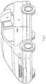
- eine Großraumlimousine mit einem andeutungsweise dargestellten, erfindungsgemäßen Fahrzeugschiebefenster,
- Fig. 2:
- das erfindungsgemäße Fahrzeugschiebefenster in einer ersten Ausführungsform in der geschlossenen und geöffneten Stellung,
- Fig. 3:
- das Fahrzeugschiebefenster gem. der
Figur 2 im geöffneten Zustand in perspektivischer Darstellung, -
Figuren 4 bis 6: -
das erfindungsgemäße Fahrzeugschiebefenster in einer zweiten Ausführung in drei verschiedenen Stellungen, - Fig. 7:
- das Fahrzeugschiebefenster gem. den
Figuren 4 bis 6 im ausgestelltem Zustand in perspektivischer Darstellung, - Fig. 8:
- eine der
Figur 7 entsprechende Darstellung jedoch im geöffneten Zustand, - Fig. 9:
- den aus Rundstäben bestehenden Rahmen, die Führungsschiene und die Scheiben in einer Explosivdarstellung einschließlich weiterer Bauteile,
- Fig. 10:
- eine der Figur 9 entsprechende Darstellung, jedoch bei geschlossenen Scheiben,
- Fig. 11:
- eine der
Figur 10 entsprechende Darstellung mit geöffneten Scheiben, - Fig. 12:
- das Fenster entsprechend
Figur 2 in teilweise geschnittener, perspektivischer Darstellung, - Fig. 13:
- das Fenster nach Fig. 12 in vergrößerter Darstellung des Verstell- und Schiebemechanismus aus dem Ausschnitt A von Fig. 12
- Fig. 14:
- eine Querschnittsansicht nach dem Pfeil X aus Fig. 13,
- Figuren 15 - 17:
-
den Fenstermechanismus nach denFiguren 12 bis 14 in verschiedenen Zwischenstufen, - Fig. 18:
- eine abgewandelte Ausführungsform eines Verschiebe- und Ausstellmechanismus,
- Fig. 19, 20:
-
zwei Darstellungen ähnlich Fig. 13, jedoch mit einer weiteren Ausführung für einen Verschiebe- und Verstellmechanismus und - Fig. 21:
- eine Darstellung eines Ausstellmechanismus in einer weiter abgewandelten Ausführungsform
- Fig. 1 :
- a MPV with a vehicle sliding window according to the invention shown in a hint,
- Fig. 2 :
- the vehicle sliding window according to the invention in a first embodiment in the closed and open position,
- Fig. 3 :
- the vehicle sliding window acc. 2 in the open state in a perspective view,
- Figures 4 to 6:
-
the vehicle sliding window according to the invention in a second embodiment in three different positions, - Fig. 7 :
- the vehicle sliding window acc. FIGS. 4 to 6 in the exposed state in a perspective view,
- Fig. 8 :
- 7 shows a representation corresponding to FIG. 7 but in the open state,
- Fig. 9 :
- the frame consisting of round bars, the guide rail and the disks in an exploded view including other components,
- Fig. 10 :
- 9 shows a representation corresponding to FIG. 9, but with the panes closed,
- Fig. 11 :
- 10 shows a representation corresponding to FIG. 10 with the disks open,
- Fig. 12 :
- the window corresponding to Figure 2 in a partially sectioned perspective view,
- Fig. 13 :
- 12 shows the window according to FIG. 12 in an enlarged illustration of the adjusting and sliding mechanism from section A of FIG. 12
- Fig. 14 :
- 13 shows a cross-sectional view according to arrow X from FIG. 13,
- Figures 15 - 17 :
-
the window mechanism according to Figures 12 to 14 in various intermediate stages, - Fig. 18 :
- a modified embodiment of a sliding and opening mechanism,
- 19, 20 :
-
two representations similar to FIG. 13, but with a further embodiment for a displacement and adjustment mechanism and - Fig. 21 :
- a representation of an opening mechanism in a further modified embodiment
In den Figuren 2 und 3 ist in schematischer Form eine erste Ausführungsform eines solchen Fahrzeugschiebefenster dargestellt. An den seitlichen Karosserieteilen ist ein im Querschnitt winkelförmiger Grundrahmen 3 festgelegt. Das Fahrzeugschiebefenster 2 umfaßt eine vordere Scheibe 4 und eine hintere Scheibe 5. In der unteren Darstellung ist das Fenster in der geschlossenen Stellung gezeichnet. Dabei liegen die beiden Scheiben 4, 5 in einer Ebene fluchtend zueinander. Die Vorwärtsfahrtrichtung der Großraumlimousine 1 ist durch den Pfeil A in der Figur 2 gekennzeichnet. Die vordere Scheibe 4 ist um eine vorn liegende, vertikale Achse 6 verschwenkbar und damit um diese Achse ausstellbar. Diese ausgestellte Stellung ist in der oberen Darstellung gezeichnet. Die Schwenkbewegung ist in Fig. 2 durch den Doppelpfeil B angedeutet. An der der Drehachse 6 gegenüberliegenden Seite ist die Scheibe 4 mit einem als Ganzes mit 7 bezeichneten Ausstellbeschlag ausgerüstet, der vom Fahrzeuginneren her zu betätigen ist. Der Ausstellbeschlag 7 ist auf einer Führungsstange 8 verschiebbar. Alternativ dazu ist es auch möglich, den Beschlag 7 am Trägerrahmen selbst unverschiebbar zu befestigen.A first embodiment of such a vehicle sliding window is shown in schematic form in FIGS. 2 and 3. A
In der ausgestellten Stellung der vorderen Scheibe 4 wird der Ausstellbeschlag 7 zur Achse 6 hin verfahren. Die hintere Scheibe 5 ist ebenfalls auf der Führungsstange 8 verschiebbar. Dazu ist sie innenseitig mit Lagerböcken 9 versehen. An der der vorderen Scheibe 4 abgewandten Seite ist sie außerdem innenseitig mit einem Schiebegriff 10 ausgerüstet. Die Länge der vorderen Scheibe 4 ist in etwa doppelt so groß wie die Länge der hinteren Scheibe 5. Die Scheibenabmessungen können selbstverständlich auch in einem anderen Verhältnis zueinander stehen. Dadurch besteht die Möglichkeit, daß nach dem Ausstellen der vorderen Scheibe 4 die hintere Scheibe 5 in Richtung zur Achse 6 hin soweit verfahren werden kann, daß die beiden hinteren Enden der Scheiben 4, 5 auf gleicher Höhe nebeneinander stehen. Dadurch wird eine Lüftungsöffnung geschaffen, die der Größe der hinteren Scheibe 5 entspricht. Es ergibt sich aus der Figur 2 von selbst, daß bei diesem Beispiel nur die vordere Scheibe 4 eine Ausstellbewegung ausführen kann, um einen Lüftungsschlitz von relativ geringer Breite zu bilden, während die hintere Scheibe 5 in Pfeilrichtung C hin und her verschiebbar ist.In the extended position of the
Die Figur 3 zeigt eine der Darstellung nach der Figur 2 in perspektivischer Darstellung bei geöffnetem Fahrzeugschiebefenster 2 gem. der oberen Darstellung in der Figur 2. Aus Gründen der vereinfachten Darstellung sind die Führungsstange 8 sowie die Lagerböcke 9 in Fig. 3 nicht dargestellt.FIG. 3 shows a perspective view of the representation according to FIG. 2 with the
In den Figuren 4 - 8 ist eine zweite Ausführung des erfindungsgemäßen Fahrzeugschiebefensters 2 dargestellt. In diesen Figuren sind die gleichen Bauteile durch die gleichen Bezugszeichen gekennzeichnet. Auch dieses Fahrzeugschiebefenster kann asymmetrisch in der Form 10 geteilt sein, so daß die Länge der vorderen Scheibe 4 doppelt oder annähernd doppelt so groß ist wie die Länge der hinteren Scheibe 5. Hier ist die vordere Scheibe 4 mittels eines Ausstellbeschlages 7 ausstellbar. Die hintere Scheibe 5 ist unbeweglich an der Karosserie befestigt. Die Führungsstange 8, die auch Teil eines aus Rundstäben gefertigten Rahmens sein kann, folgt der Ausstellbewegung der vorderen Scheibe 4. Am unteren, gegebenenfalls auch am oberen Rand der Scheibe 4 ist eine Führungsschiene 11 befestigt. Die Führungsschiene 11 ist in einem ortsfesten Führungsschienenhalter 12 geführt. Auf der Führungsstange 8 ist außerdem eine Scheibenaufnahme 13 verschiebbar angeordnet, die im wesent-lichen aus zwei endseitigen Buchsen und einer Aufnahme für die Führungsschiene 11 besteht. Die Figur 4 zeigt die Schließlage der beiden Scheiben 4 und 5. In dieser Stellung stehen beide Scheiben wieder fluchtend zueinander. Durch Betätigen des Ausstellbeschlages 7 wird die vordere Scheibe 4 nach außen ausgestellt, so daß die beiden Scheiben 4, 5 in einem Winkel zueinander stehen. Am vorderen Rand der vorderen Scheibe 4 ist wiederum ein Schiebegriff 10 angeordnet, die vordere Scheibe 4 entgegen der Vorwärtsfahrtrichtung nach hinten zu verschieben, um dadurch eine Lüftungsöffnung zu bilden.FIGS. 4-8 show a second embodiment of the
Die Figur 5 zeigt die ausgestellte Stellung der Scheibe 4, während die Figur 6 die geöffnete Stellung zeigt, in der der hintere Bereich der vorderen Scheibe 4 nach außen gegenüber der hinteren Scheibe 5 versetzt ist. Die hintere Scheibe 5 ist bei dem Ausführungsbeispiel gem. der Figur 4 - 8 ortsfest, d.h. sie kann weder ausgestellt noch verschoben werden.FIG. 5 shows the deployed position of the
Die Figuren 7 u. 8 zeigen das Fahrzeugschiebefenster 2 der vorbeschriebenen Ausführung in perspektivischer Darstellung. Die Figur 7 zeigt die ausgestellte Stellung, die Figur 8 die geöffnete Stellung. Aus Gründen der vereinfachten Darstellung ist die Führungsstange 8 nicht dargestellt. Die Vorwärtsfahrtrichtung ist durch den Pfeil A gekennzeichnet. Aus der Figur 8 ergibt sich, daß die Größe der Öffnung in etwa der Größe der hinteren ortsfesten Scheibe 5 entspricht.Figures 7 u. 8 show the
Die Figuren 9 - 11 zeigen die komplette vordere Scheibe 4 mit den zugehörigen Beschlagteilen. Die Scheibenaufnahme 13 besteht aus den beiden äußeren Linearbuchsen 13 a und der dazwischenliegenden Aufnahmebuchse 13 b.FIGS. 9-11 show the complete
Die Figur 10 zeigt, daß die Scheibenaufnahme 13 auf der Führungsstange 8 verschiebbar ist. Im hinteren Bereich der vorderen Scheibe 4 ist der Führungsschienenhalter 12 angeordnet. Außerdem zeigt die Figur 10, daß die Führungsschiene 11 in nicht näher erläuterter Weise am Rand der vorderen Scheibe 4 festgelegt ist. Die Führungsstange 8 kann Teil eines Rahmens sein, wobei der vordere vertikale Holm durch das Bezugszeichen 8 a gekennzeichnet ist. Auf den vertikalen Holm 8 a ist eine Lagerhülse 14 aufgesetzt, die an dem Grundrahmen 3 (Fig. 4 bis 6) befestigt ist. Die Mittelachse 6 der Lagerhülse 14 ist die Schwenkachse für die Ausstellbewegung der vorderen Scheibe 4.Figure 10 shows that the
Die Figur 11 zeigt, wie die vordere Scheibe 4 seitlich neben die hintere ortsfeste Scheibe 5 geschoben werden kann. Dabei bildet der Führungsschienenhalter einen Anschlag für die Schiebebewegung, da die Scheibenaufnahme 13 dagegen schlägt. Das Schließen der jeweiligen Scheibbe 4 bzw. 5 erfolgt in der umgekehrten Reihenfolge.FIG. 11 shows how the
Die Figuren 12 - 18 zeigen eine weitere Ausführungsform für einen Schiebe- und Ausstellmechanismus im Detail. Da es sich dabei um eine in der Praxis bevorzugt eingesetzte Variante handelt, wird diese im folgenden näher erläutert. Da die mechanischen Funktionen mit den anderen Ausführungsbeispielen weitgehend übereinstimmen, gilt das hier gesagte insoweit auch für die anderen Varianten.FIGS. 12-18 show a further embodiment for a sliding and opening mechanism in detail. Since this is a variant which is preferably used in practice, it is explained in more detail below. Since the mechanical functions largely correspond to the other exemplary embodiments, what has been said here also applies to the other variants.
In Figur 12 umfaßt der Ausstellmechanismus eine vertikale Achse 20, die mit ihrem unteren Ende in einer Tragschiene 21 gelagert ist. An die Tragschiene 21 ist an mehreren Stellen die in Fahrtrichtung hintere Scheibe 33 angeklebt oder in anderer geeigneten Weise befestigt. Die Tragschiene 21 ist auf den unteren horizontalen Profilholm 22 so aufgesetzt, daß er auf diesem frei gleiten kann. Der Profilholm 22 bildet gleichzeitig den unteren Teil des Trägerrahmens 3. Der obere entsprechende Profilholm des Rahmens 3 ist mit 23 bezeichnet. Die seitlichen vertikalen Holme des Rahmens tragen die Bezugsziffern 24 und 25. Der Profilrahmen ist mittels Schrauben 26' an dem Rand des Karosserieausschnittes angeschraubt.In FIG. 12, the opening mechanism comprises a
Die vertikale Achse 20, die an ihrem oberen Ende mittels einer geeigneten, nicht dargestellten Handhabe verdreht werden kann, besitzt an ihrem unteren Ende eine Nase 26, in die ein Mitnahmestift 27 eingesetzt ist, der beim Verdrehen der Achse 20 um ihre virtuelle Achse von der Nase 26 exzentrisch mitgenommen wird. Der Mitnahmestift 27 greift an dem Ende eines Kulissenhebels 28 an, der den eigentlichen Ausstellhebel bildet und mit seinem anderen Ende mit einem Führungsstift 29 gekoppelt ist, der wiederum an der Tragschiene 21 befestigt ist und nach oben hin so vorsteht, daß er in eine Nut 30 eingreift, die sich im hinteren Teil des Ausstellhebels 28 befindet. Das dem Führungsstift 29 zugeordnete Ende des Ausstellhebels 28 weist einen Gleitschuh 31 auf, der in einer Profilschiene 32 gleitet, an die das in Vorwärtsfahrtrichtung vordere Ausstellfenster 34 angeklebt ist. Der Gleitschuh 31 ist durch einen Stift 35 mit dem zugeordneten Ende des Ausstellhebels 28 verbunden. Die Ausstellbewegung der Scheibe 34 wird erreicht, indem die Achse 20 z. B. von Hand um ihre virtuelle Achse so verdreht wird, daß über den Mitnahmestift 27 der Ausstellhebel 28 und damit zwangsläufig der daran befestigte Gleitschuh 31 in Pfeilrichtung 36 (Fig. 16) verschoben wird. Durch diese Verschiebebewegung gleitet der Ausstellhebel 28 mit den Innenwänden der durch eine geeignete Bahnkrümmung angepaßten Nut 30 an dem Führungsstift 29 entlang und stellt die Ausstellscheibe 34 aus. Diese Ausstellposition, zeigt die Figur 15. Ist diese Ausstellposition erreicht, kann unmittelbar daran anschließend das in Fahrtrichtung hintere Schiebefenster 33 über eine nicht dargestellte Handhabe mit seinen zugehörigen Bau- und Funktionsteilen 20, 21 und 24 bis 29 sowie 31 in Pfeilrichtung 37 (Fig. 12, 15) verschoben werden. Dabei wird die Ausstellscheibe 34 immer weiter ausgestellt. Beim Schließen der Scheibe 33, d. h. beim Zurückziehen des Schiebefensters 33 in seine Geschlossenstellung wird das Ausstellfenster 34 entsprechend zunehmend weiter zugestellt, bis es die in Fig. 15 gezeigte Position eingenommen hat.The
Die Figur 18 zeigt eine Ausführungsform für einen Ausstellmechanismus, bei dem statt des Ausstellhebels 28 in den Figuren 12 - 17 ein abgewandelter Ausstellhebel 38 vorgesehen ist, der mit seinem der Ausstellscheibe 34 zugewandten Ende an einem Gleitschuh 39 angelenkt ist, der eine Nut 30' aufweist, in der ein Stift 41 gleitet, der die Funktion des Führungsstiftes 29 aus Fig. 13 hat. Ansonsten sind die Bewegungsabläufe zwischen der Variante nach Fig. 13 und der Ausführung nach Fig. 18 entsprechend. Soweit gleiche Teile verwendet werden, stimmen die Bezugszeichen mit denen nach Fig. 13 überein.FIG. 18 shows an embodiment for an opening mechanism in which, instead of the opening
Entsprechendes gilt für die Variante nach Fig. 19, in der die Nase 26 aus Fig. 13 unmittelbar an einem Gleitschuh 39' angreift und so eine exzentrische Bewegung auslöst. Der Gleitschuh gleitet in der Führungsschiene 32 entlang.The same applies to the variant according to FIG. 19, in which the
Figur 20 stellt eine teilweise geschnittene Draufsicht auf die Ausführung von Fig. 19 dar.FIG. 20 shows a partially sectioned top view of the embodiment of FIG. 19.
Bei der Abwandlung von Fig. 21 ist das der Scheibe 33 zugeordnete Ende des Ausstellhebels gegenüber den anderen vorbeschriebenen Ausführungen geändert worden. Auch wurde der Drehpunkt 42 für den Ausstellhebel 28' verlagert.In the modification of FIG. 21, the end of the deployment lever assigned to the
Selbstverständlich ist es im Rahmen der Erfindung auch möglich, das Erfindungsprinzip bei ausstellbaren Schiebedeckeln anzuwenden, die sich in der Dachhaut eines Fahrzeugs befinden. Ebenso ist es denkbar, das erfindungsgemäße Ausstellfenster statt über eine feststehende Scheibe, wie in den Figuren 4 - 6 dargestellt, unmittelbar nach außen auszustellen und über die Karosserie hinweg zu schieben. In diesem Fall kann die gleiche Mechanik verwendet werden, wie bei den vorstehend beschriebenen Ausführungsbeispielen.It is of course also possible within the scope of the invention to apply the principle of the invention to sliding covers which can be opened and which are located in the roof skin of a vehicle. It is also conceivable to open the opening window according to the invention directly to the outside instead of via a fixed pane, as shown in FIGS. 4-6, and to slide it over the body. In this case, the same mechanics can be used as in the exemplary embodiments described above.
Claims (26)
Applications Claiming Priority (2)
| Application Number | Priority Date | Filing Date | Title |
|---|---|---|---|
| DE4416827A DE4416827A1 (en) | 1994-05-16 | 1994-05-16 | Vehicle sliding window |
| DE4416827 | 1994-05-17 |
Publications (2)
| Publication Number | Publication Date |
|---|---|
| EP0683064A1 true EP0683064A1 (en) | 1995-11-22 |
| EP0683064B1 EP0683064B1 (en) | 1998-06-10 |
Family
ID=6517999
Family Applications (1)
| Application Number | Title | Priority Date | Filing Date |
|---|---|---|---|
| EP95105078A Expired - Lifetime EP0683064B1 (en) | 1994-05-16 | 1995-04-05 | Sliding window for vehicle |
Country Status (4)
| Country | Link |
|---|---|
| EP (1) | EP0683064B1 (en) |
| JP (1) | JPH07305558A (en) |
| DE (2) | DE4416827A1 (en) |
| ES (1) | ES2121246T3 (en) |
Cited By (12)
| Publication number | Priority date | Publication date | Assignee | Title |
|---|---|---|---|---|
| EP0949397A1 (en) * | 1998-04-08 | 1999-10-13 | Renault | Device for the mounting with translation of a sliding window, in particular on a vehicle door |
| EP0962346A1 (en) * | 1998-06-05 | 1999-12-08 | Wagon Automotive Snc | Closing device for an aperture of a vehicle body, with exterior sliding and method for manufacturing and corresponding installation |
| EP1084879A2 (en) * | 1999-09-15 | 2001-03-21 | Construcciones Radio Electro-Mecanicas Sistemas de Automocion, S.L. | Sliding window for motor vehicles |
| FR2851960A1 (en) * | 2003-03-03 | 2004-09-10 | Dura Automotive Plettenber Ent | GLASS MODULE, PARTICULARLY SLIDING GLASS, FOR A VEHICLE, PARTICULARLY A MOTOR VEHICLE AS WELL AS A VEHICLE PROVIDED WITH SUCH A MODULE |
| EP1595727A1 (en) * | 2004-05-13 | 2005-11-16 | Wagon Sas | Closing device for an opening in a body of a vehicle, method of manufacturing and correspondig vehicle. |
| FR2878882A1 (en) * | 2004-12-03 | 2006-06-09 | Wagon Sas | Body`s opening e.g. flush type opening, closing device for e.g. motor truck, has knuckle joint type half-open control unit integrated with one of rails, for permitting passage of movable panel from closing position to half-open position |
| EP0778168B2 (en) † | 1995-12-08 | 2007-02-14 | Wagon Automotive Snc | Closing device, flush mounted on a vehicle opening |
| EP1074409B2 (en) † | 1999-08-06 | 2009-08-05 | Wagon Sas | Window panel with internal seal in an opening in a vehicle window |
| EP2228244A1 (en) | 2009-03-13 | 2010-09-15 | Pilkington Italia S.p.A. | Slideable window |
| EP2228245A1 (en) | 2009-03-13 | 2010-09-15 | Pilkington Italia S.p.A. | Slideable window |
| RU2487818C1 (en) * | 2012-02-09 | 2013-07-20 | Открытое Акционерное Общество "Авиационная Холдинговая Компания "Сухой" | Canopy displacing and locking mechanism |
| DE102013218388A1 (en) | 2013-09-13 | 2015-03-19 | Volkswagen Aktiengesellschaft | Vehicle with at least one window opening for a window pane |
Families Citing this family (11)
| Publication number | Priority date | Publication date | Assignee | Title |
|---|---|---|---|---|
| FR2781186B1 (en) * | 1998-07-16 | 2000-09-22 | Wagon Automotive | DEVICE FOR SHUTTERING A HOUSING IN THE BODY OF A VEHICLE, WITH ROTATING HANDLE |
| FR2792881B1 (en) * | 1999-04-27 | 2001-07-20 | Wagon Automotive Snc | DEVICE FOR SHUTTERING A HOUSING IN THE BODY OF A VEHICLE, WITH SEALING AND / OR RIGIDIFICATION ELEMENT (S) AND MANUFACTURING METHOD THEREOF |
| HU2733U (en) * | 2003-12-08 | 2004-05-28 | Koenig Jarmueablak Szerkezet G | Window structure for motor vehicles |
| FR2937910A1 (en) * | 2008-11-06 | 2010-05-07 | Wagon Sas | DEVICE FOR OBTURING A BAY OF A MOTOR VEHICLE WITH A SLIDING PANEL AND CORRESPONDING VEHICLE |
| FR2937912B1 (en) * | 2008-11-06 | 2010-12-24 | Wagon Sas | DEVICE FOR SEALING A BAY OF A MOTOR VEHICLE WITH AID FOR THE REMOVAL OF A SLIDING PANEL AND CORRESPONDING VEHICLE |
| GB2497776A (en) * | 2011-12-20 | 2013-06-26 | Gm Global Tech Operations Inc | Vehicle side window having a sliding window pane |
| DE102015210564A1 (en) | 2015-06-09 | 2016-12-15 | Volkswagen Aktiengesellschaft | Vehicle with at least one window opening for a window pane |
| DE102018106168A1 (en) | 2018-03-16 | 2019-09-19 | Volkswagen Aktiengesellschaft | vehicle window |
| DE102020113288A1 (en) | 2020-05-15 | 2021-11-18 | Bayerische Motoren Werke Aktiengesellschaft | WINDOW FRAME FOR WINDOW OPENING SYSTEM |
| DE102020113292A1 (en) | 2020-05-15 | 2021-11-18 | Bayerische Motoren Werke Aktiengesellschaft | WINDOW FRAME FOR WINDOW OPENING SYSTEM |
| DE102020113286A1 (en) | 2020-05-15 | 2021-11-18 | Bayerische Motoren Werke Aktiengesellschaft | WINDOW OPENING SYSTEM FOR VEHICLE SIDE GLASS |
Citations (4)
| Publication number | Priority date | Publication date | Assignee | Title |
|---|---|---|---|---|
| CH342483A (en) * | 1955-05-14 | 1959-11-15 | Auto Union Gmbh | Windows, in particular for motor vehicles |
| US4295306A (en) * | 1979-05-29 | 1981-10-20 | Caterpillar Tractor Co. | Window clip retainer |
| DE3803342A1 (en) * | 1987-02-06 | 1988-11-10 | Aisin Seiki | SIDE WINDOW ARRANGEMENT FOR A MOTOR VEHICLE |
| EP0445685A1 (en) * | 1990-03-07 | 1991-09-11 | Heywood Williams Limited | Sliding window or door |
Family Cites Families (2)
| Publication number | Priority date | Publication date | Assignee | Title |
|---|---|---|---|---|
| GB583735A (en) * | 1944-11-24 | 1946-12-30 | Auster Ltd | Improvements relating to ventilation panels or windows |
| DE6750655U (en) * | 1968-06-21 | 1969-01-09 | Roth P Gmbh | HORIZONTAL SLIDING WINDOWS FOR MOTOR VEHICLES |
-
1994
- 1994-05-16 DE DE4416827A patent/DE4416827A1/en not_active Withdrawn
-
1995
- 1995-04-05 ES ES95105078T patent/ES2121246T3/en not_active Expired - Lifetime
- 1995-04-05 EP EP95105078A patent/EP0683064B1/en not_active Expired - Lifetime
- 1995-04-05 DE DE59502463T patent/DE59502463D1/en not_active Expired - Fee Related
- 1995-05-15 JP JP7115923A patent/JPH07305558A/en active Pending
Patent Citations (4)
| Publication number | Priority date | Publication date | Assignee | Title |
|---|---|---|---|---|
| CH342483A (en) * | 1955-05-14 | 1959-11-15 | Auto Union Gmbh | Windows, in particular for motor vehicles |
| US4295306A (en) * | 1979-05-29 | 1981-10-20 | Caterpillar Tractor Co. | Window clip retainer |
| DE3803342A1 (en) * | 1987-02-06 | 1988-11-10 | Aisin Seiki | SIDE WINDOW ARRANGEMENT FOR A MOTOR VEHICLE |
| EP0445685A1 (en) * | 1990-03-07 | 1991-09-11 | Heywood Williams Limited | Sliding window or door |
Cited By (20)
| Publication number | Priority date | Publication date | Assignee | Title |
|---|---|---|---|---|
| EP0778168B2 (en) † | 1995-12-08 | 2007-02-14 | Wagon Automotive Snc | Closing device, flush mounted on a vehicle opening |
| FR2777228A1 (en) * | 1998-04-08 | 1999-10-15 | Renault | TRANSLATION MOUNTING DEVICE FOR A SLIDING WINDOW, PARTICULARLY ON A MOTOR VEHICLE DOOR |
| EP0949397A1 (en) * | 1998-04-08 | 1999-10-13 | Renault | Device for the mounting with translation of a sliding window, in particular on a vehicle door |
| EP0962346A1 (en) * | 1998-06-05 | 1999-12-08 | Wagon Automotive Snc | Closing device for an aperture of a vehicle body, with exterior sliding and method for manufacturing and corresponding installation |
| FR2779389A1 (en) * | 1998-06-05 | 1999-12-10 | Wagon Automotive | DEVICE FOR SHUTTERING A HOUSING IN THE BODY OF A VEHICLE, WITH OUTSIDE SLIDING, AND METHOD FOR MANUFACTURING AND MOUNTING THEREOF |
| EP1074409B2 (en) † | 1999-08-06 | 2009-08-05 | Wagon Sas | Window panel with internal seal in an opening in a vehicle window |
| EP1084879A2 (en) * | 1999-09-15 | 2001-03-21 | Construcciones Radio Electro-Mecanicas Sistemas de Automocion, S.L. | Sliding window for motor vehicles |
| EP1084879A3 (en) * | 1999-09-15 | 2002-07-03 | Construcciones Radio Electro-Mecanicas Sistemas de Automocion, S.L. | Sliding window for motor vehicles |
| DE10309185B8 (en) * | 2003-03-03 | 2010-08-05 | Volkswagen Ag | Sliding window for a vehicle |
| DE10309185A1 (en) * | 2003-03-03 | 2004-09-23 | Dura Automotive Plettenberg Entwicklungs- Und Vertriebs Gmbh | Glass module, in particular sliding window, for a vehicle, in particular a motor vehicle |
| DE10309185B4 (en) * | 2003-03-03 | 2010-04-08 | Volkswagen Ag | Sliding window for a vehicle |
| FR2851960A1 (en) * | 2003-03-03 | 2004-09-10 | Dura Automotive Plettenber Ent | GLASS MODULE, PARTICULARLY SLIDING GLASS, FOR A VEHICLE, PARTICULARLY A MOTOR VEHICLE AS WELL AS A VEHICLE PROVIDED WITH SUCH A MODULE |
| FR2870167A1 (en) * | 2004-05-13 | 2005-11-18 | Wagon Automotive Sas Soc Par A | DEVICE FOR SEALING A BAY MADE IN THE BODYWORK OF A MOTOR VEHICLE, METHOD OF MANUFACTURING THE SAME |
| EP1595727A1 (en) * | 2004-05-13 | 2005-11-16 | Wagon Sas | Closing device for an opening in a body of a vehicle, method of manufacturing and correspondig vehicle. |
| FR2878882A1 (en) * | 2004-12-03 | 2006-06-09 | Wagon Sas | Body`s opening e.g. flush type opening, closing device for e.g. motor truck, has knuckle joint type half-open control unit integrated with one of rails, for permitting passage of movable panel from closing position to half-open position |
| EP1674644A1 (en) * | 2004-12-03 | 2006-06-28 | Wagon Sas | Closing device for an opening, sliding in partly-opened position, corresponding vehicle and process |
| EP2228244A1 (en) | 2009-03-13 | 2010-09-15 | Pilkington Italia S.p.A. | Slideable window |
| EP2228245A1 (en) | 2009-03-13 | 2010-09-15 | Pilkington Italia S.p.A. | Slideable window |
| RU2487818C1 (en) * | 2012-02-09 | 2013-07-20 | Открытое Акционерное Общество "Авиационная Холдинговая Компания "Сухой" | Canopy displacing and locking mechanism |
| DE102013218388A1 (en) | 2013-09-13 | 2015-03-19 | Volkswagen Aktiengesellschaft | Vehicle with at least one window opening for a window pane |
Also Published As
| Publication number | Publication date |
|---|---|
| EP0683064B1 (en) | 1998-06-10 |
| ES2121246T3 (en) | 1998-11-16 |
| DE4416827A1 (en) | 1995-11-23 |
| JPH07305558A (en) | 1995-11-21 |
| DE59502463D1 (en) | 1998-07-16 |
Similar Documents
| Publication | Publication Date | Title |
|---|---|---|
| EP0683064A1 (en) | Sliding window for vehicle | |
| EP1782979B1 (en) | Gapless roller blind for rear window | |
| DE3623468C2 (en) | ||
| DE3124325C2 (en) | ||
| EP0395847B1 (en) | Actuator assembly for a motorised folding top | |
| DE3733892C2 (en) | ||
| DE19520348C1 (en) | Wind deflector for vehicle sunroof frame | |
| DE60033129T2 (en) | DETACHABLE ROOF MODULE FOR A MOTOR VEHICLE AND WITH A MODULE EQUIPPED MOTOR VEHICLE | |
| EP0331910A2 (en) | Sliding roof for motor vehicles | |
| EP0119433A2 (en) | Fitting for a wing of a window, door or the like, which is at least tiltable and movable from one plane to a second parallel plane | |
| EP3468820B1 (en) | Construction machine, in particular a soil compacting machine, specifically a rubber-wheeled roller, method for operating a construction machine and method for producing a construction machine | |
| DE60030904T2 (en) | Construction of an openable vehicle roof | |
| DE60017035T2 (en) | Construction of an openable roof | |
| DE3822050C2 (en) | ||
| EP0220414A2 (en) | Body for passenger cars | |
| DE3405994C2 (en) | Cable window regulator | |
| DE3823087C2 (en) | ||
| DE3129900A1 (en) | Tilt-and-slide sunroof for motor vehicles | |
| EP1752325B1 (en) | Roof system for a car | |
| AT3729U1 (en) | REAR DOOR FOR A MOTOR VEHICLE | |
| DE10257673A1 (en) | Closure device of an opening provided in the body of a vehicle, and corresponding vehicle | |
| EP0905343B1 (en) | Window or door arrangement | |
| DE19824404A1 (en) | Vehicle with at least one sliding side door | |
| EP1354759A1 (en) | Extendable loading platform | |
| DE3138114C2 (en) |
Legal Events
| Date | Code | Title | Description |
|---|---|---|---|
| PUAI | Public reference made under article 153(3) epc to a published international application that has entered the european phase |
Free format text: ORIGINAL CODE: 0009012 |
|
| AK | Designated contracting states |
Kind code of ref document: A1 Designated state(s): DE ES FR GB IT SE |
|
| 17P | Request for examination filed |
Effective date: 19951020 |
|
| RAP1 | Party data changed (applicant data changed or rights of an application transferred) |
Owner name: SCHADE GMBH & CO. KG |
|
| 17Q | First examination report despatched |
Effective date: 19960926 |
|
| GRAG | Despatch of communication of intention to grant |
Free format text: ORIGINAL CODE: EPIDOS AGRA |
|
| GRAG | Despatch of communication of intention to grant |
Free format text: ORIGINAL CODE: EPIDOS AGRA |
|
| GRAH | Despatch of communication of intention to grant a patent |
Free format text: ORIGINAL CODE: EPIDOS IGRA |
|
| GRAH | Despatch of communication of intention to grant a patent |
Free format text: ORIGINAL CODE: EPIDOS IGRA |
|
| GRAA | (expected) grant |
Free format text: ORIGINAL CODE: 0009210 |
|
| AK | Designated contracting states |
Kind code of ref document: B1 Designated state(s): DE ES FR GB IT SE |
|
| REF | Corresponds to: |
Ref document number: 59502463 Country of ref document: DE Date of ref document: 19980716 |
|
| ITF | It: translation for a ep patent filed |
Owner name: DE DOMINICIS & MAYER S.R.L. |
|
| GBT | Gb: translation of ep patent filed (gb section 77(6)(a)/1977) |
Effective date: 19980911 |
|
| ET | Fr: translation filed | ||
| REG | Reference to a national code |
Ref country code: ES Ref legal event code: FG2A Ref document number: 2121246 Country of ref document: ES Kind code of ref document: T3 |
|
| PLBE | No opposition filed within time limit |
Free format text: ORIGINAL CODE: 0009261 |
|
| STAA | Information on the status of an ep patent application or granted ep patent |
Free format text: STATUS: NO OPPOSITION FILED WITHIN TIME LIMIT |
|
| 26N | No opposition filed | ||
| REG | Reference to a national code |
Ref country code: GB Ref legal event code: IF02 |
|
| PGFP | Annual fee paid to national office [announced via postgrant information from national office to epo] |
Ref country code: SE Payment date: 20040419 Year of fee payment: 10 |
|
| PGFP | Annual fee paid to national office [announced via postgrant information from national office to epo] |
Ref country code: DE Payment date: 20050311 Year of fee payment: 11 |
|
| PGFP | Annual fee paid to national office [announced via postgrant information from national office to epo] |
Ref country code: GB Payment date: 20050324 Year of fee payment: 11 |
|
| PG25 | Lapsed in a contracting state [announced via postgrant information from national office to epo] |
Ref country code: IT Free format text: LAPSE BECAUSE OF NON-PAYMENT OF DUE FEES Effective date: 20050405 |
|
| PG25 | Lapsed in a contracting state [announced via postgrant information from national office to epo] |
Ref country code: SE Free format text: LAPSE BECAUSE OF NON-PAYMENT OF DUE FEES Effective date: 20050406 |
|
| PGFP | Annual fee paid to national office [announced via postgrant information from national office to epo] |
Ref country code: ES Payment date: 20050415 Year of fee payment: 11 |
|
| EUG | Se: european patent has lapsed | ||
| PG25 | Lapsed in a contracting state [announced via postgrant information from national office to epo] |
Ref country code: GB Free format text: LAPSE BECAUSE OF NON-PAYMENT OF DUE FEES Effective date: 20060405 |
|
| PG25 | Lapsed in a contracting state [announced via postgrant information from national office to epo] |
Ref country code: ES Free format text: LAPSE BECAUSE OF NON-PAYMENT OF DUE FEES Effective date: 20060406 |
|
| PGFP | Annual fee paid to national office [announced via postgrant information from national office to epo] |
Ref country code: FR Payment date: 20060426 Year of fee payment: 12 |
|
| PG25 | Lapsed in a contracting state [announced via postgrant information from national office to epo] |
Ref country code: DE Free format text: LAPSE BECAUSE OF NON-PAYMENT OF DUE FEES Effective date: 20061101 |
|
| GBPC | Gb: european patent ceased through non-payment of renewal fee |
Effective date: 20060405 |
|
| REG | Reference to a national code |
Ref country code: ES Ref legal event code: FD2A Effective date: 20060406 |
|
| PG25 | Lapsed in a contracting state [announced via postgrant information from national office to epo] |
Ref country code: FR Free format text: LAPSE BECAUSE OF NON-PAYMENT OF DUE FEES Effective date: 20070430 |