EP0682787B1 - Methods and apparatus for modular computer construction - Google Patents
Methods and apparatus for modular computer construction Download PDFInfo
- Publication number
- EP0682787B1 EP0682787B1 EP94909566A EP94909566A EP0682787B1 EP 0682787 B1 EP0682787 B1 EP 0682787B1 EP 94909566 A EP94909566 A EP 94909566A EP 94909566 A EP94909566 A EP 94909566A EP 0682787 B1 EP0682787 B1 EP 0682787B1
- Authority
- EP
- European Patent Office
- Prior art keywords
- base
- assembly
- frame
- shield
- top cover
- Prior art date
- Legal status (The legal status is an assumption and is not a legal conclusion. Google has not performed a legal analysis and makes no representation as to the accuracy of the status listed.)
- Expired - Lifetime
Links
Images



Classifications
-
- G—PHYSICS
- G06—COMPUTING OR CALCULATING; COUNTING
- G06F—ELECTRIC DIGITAL DATA PROCESSING
- G06F1/00—Details not covered by groups G06F3/00 - G06F13/00 and G06F21/00
- G06F1/16—Constructional details or arrangements
- G06F1/18—Packaging or power distribution
-
- G—PHYSICS
- G06—COMPUTING OR CALCULATING; COUNTING
- G06F—ELECTRIC DIGITAL DATA PROCESSING
- G06F1/00—Details not covered by groups G06F3/00 - G06F13/00 and G06F21/00
- G06F1/16—Constructional details or arrangements
- G06F1/18—Packaging or power distribution
- G06F1/181—Enclosures
-
- G—PHYSICS
- G06—COMPUTING OR CALCULATING; COUNTING
- G06F—ELECTRIC DIGITAL DATA PROCESSING
- G06F1/00—Details not covered by groups G06F3/00 - G06F13/00 and G06F21/00
- G06F1/16—Constructional details or arrangements
- G06F1/18—Packaging or power distribution
- G06F1/181—Enclosures
- G06F1/182—Enclosures with special features, e.g. for use in industrial environments; grounding or shielding against radio frequency interference [RFI] or electromagnetical interference [EMI]
-
- G—PHYSICS
- G06—COMPUTING OR CALCULATING; COUNTING
- G06F—ELECTRIC DIGITAL DATA PROCESSING
- G06F1/00—Details not covered by groups G06F3/00 - G06F13/00 and G06F21/00
- G06F1/16—Constructional details or arrangements
- G06F1/20—Cooling means
Definitions
- the present invention relates generally to computer enclosure construction designs and methods. More particularly, the present invention relates to a personal computer enclosure designed to be assembled and to receive modular subassembly components substantially with minimal fasteners or other assembly hardware.
- Computer systems typically comprise numerous electronic and mechanical components and subsystems coupled together to function as a unit.
- a common arrangement of component subparts forming a personal computer system might include a central processor unit (CPU), memory devices, and input and output (I/O) controllers coupled to a main processor board, with other peripheral devices (e.g., floppy, hard, or optical mass storage drives) and functional subassemblies (e.g., power supplies) mounted elsewhere within a housing or enclosure.
- peripheral devices e.g., floppy, hard, or optical mass storage drives
- functional subassemblies e.g., power supplies
- the above subassemblies typically are installed into computer enclosures using straightforward mounting methods and hardware, including screws, damps, rivets, and brackets.
- the computer housing itself frequently may comprise a substantially rectangular metal or plastic housing having threaded through-holes or spot-welded brackets and standoffs positioned to receive the above subassemblies.
- the mechanical strength of the enclosure is obtained by providing a metal chassis to receive and support the subassemblies, and mounting a plastic shell over the chassis to provide attractive cosmetics and finish.
- subassemblies must be fastened onto the metal chassis with the above hardware using hand or machine tools.
- large metal chassis may entail higher material costs and greater weight than comparable plastic parts.
- modularity and interchangeability of system subassemblies is of great importance to manufacturers, retailers, and users alike.
- modularity is important because the manufacturer can more easily and cost effectively adapt to customer demands and technology changes without substantially redesigning or rebuilding existing products.
- products can be more easily built at a central manufacturing site, and then customized for localized domestic and foreign use.
- a retailer can more easily update stocked but unsold computer systems as more powerful subassemblies become available, or to upgrade and service customers' computer systems.
- Customers benefit from modular system designs because they initially can purchase a base system which meets their present needs, and later expand their systems' performance and storage functions by replacing components to achieve higher performance. For example, a customer may wish to replace his existing processor board with a more powerful processor board, or to replace an existing disk drive with a higher capacity mass storage device, but without requiring a dealer or other service person to perform the upgrade.
- the present invention overcomes many of the problems associated with prior art personal computer system enclosures by providing a simple, light weight yet robust, design comprising essentially five parts which can be substantially snapped together, and which uses only minimal traditional hardware elements.
- the enclosure is designed to receive all functional components and subassemblies necessary to the operation of a personal computer system without limiting access to any other subassembly.
- a personal computer system designed and assembled in accordance with the present invention can be easily and inexpensively reconfigured and updated by the manufacturer, retailer, or end user without need for time consuming disassembly and assembly operations.
- the enclosure substantially comprises a base, an internal frame, a front and a back panel, and a U-shaped top cover.
- the internal frame comprises a single piece plastic molding with appropriately formed bays designed to receive various system subassemblies, such as floppy disk drives, hard disk drives and the like. Each bay has an integrally formed flexible snap having a latch head to bear against and retain a subassembly placed in the bay.
- the base also has a plurality of frame-mounting snaps and cruciform members located on forward and rear portions of the frame which mate to complimentary receiving openings in the base.
- the front and rear panels have a plurality of panel-mounting snaps and hooks which are received by mating openings in the base, frame and top cover respectively.
- a base electromagnetic interference (EMI) shield is then fitted and secured to the base.
- the base EMI shield comprises a plurality of planar tabbed fingers formed in the periphery of the shield, each finger having a hemispherical dome centrally disposed between lateral edges of each finger.
- the base EMI shield is attached to the base such that the lateral edges of the fingers are conformal to and recessed below a peripherally extending rim on the base.
- the internal frame is located above, and snapped into place upon, the front and rear portions of the base.
- a rear EMI shield is fitted and secured to the back panel, and the panel maneuvered into position and secured the base and frame by the panel-mounting snaps and hooks.
- a plurality of subassemblies including disk drives, optical disk drives, power supplies, main processor printed circuit boards, and speaker housings are then placed into the respective bays and secured via a plurality of subassembly retaining snaps, guides, tabs, and other interlocking members.
- Electrical connection for the computer system is substantially established by routing an appropriately sized main cable bundle between the subassemblies, and connecting each subassembly to terminal ends of the cable bundle via a plurality of connectors. Additional wiring needs can be accommodated by providing and routing one or more secondary cable bundles between particular subassemblies, as for example between the main processor board and the speaker housing.
- a front EMI shield is then secured to the front panel, and the panel maneuvered into a dosed position relative to the rear of the U-shaped top cover via hooks formed on one lateral edge of the panel.
- the front panel is secured to the top cover by panel-mounting snaps formed on the opposing lateral edge mating to receiving openings in the top cover, thereby forming a four-sided top cover assembly.
- One or more bezels is detachably mounted to the front panel via hooks and snaps to permit access to the subassembly devices frontally mounted in the bays of the built up base-frame assembly.
- Each bezel may be fitted with EMI shielding as necessary to mate to the subassembly housing or the front EMI shield to effect a continuous EMI shield at the front portion of the computer system.
- top cover is lowered onto and slideably moved rearward upon a pair of inclined standoffs until the rear edges of the top cover assembly contact a plurality of contact fingers formed in the rear EMI shield, the top cover assembly resting upon on the dome-like structures of the base EMI shield fitted to the base-frame assembly.
- the top cover assembly is securely fastened to the built up base-frame assembly by conventional thumbscrews extending through the rear panel into complementary threaded through-holes in the rear flange of the top cover assembly, and by a lower edge of the front panel bearing against an extended lip formed in the front portion of the base.
- the present invention discloses a modular enclosure for personal computer systems, and methods for assembly of such an enclosure.
- specific numbers, dimensions, and configurations are set forth in order to provide a thorough understanding of the present invention.
- the present invention may be practiced without these specific details.
- well known systems are shown in diagrammatical or block diagram form in order not to obscure the present invention unnecessarily.
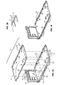
- Base 10 comprises a raised floor 11 , a periphery 16 , and a plurality of upwardly extending posts 12, where posts 12 reciprocally receive a plurality of self-clinching tanged openings 14 formed in a base electromagnetic interference (EMI) shield 15 .
- EMI electromagnetic interference
- base 10 will comprise a molded plastic part, and that base EMI shield 15 may be formed of any thin, conductive, spring-steel material as is generally known, for example 0.020" nickel plated carbon steel shim stock.
- Base EMI shield 15 further comprises a plurality of planar, tabbed fingers 17 formed in peripheral edges of the shield 15 , each finger 17 having a one or more hemispherical domes 18 proportionally disposed between lateral edges 19 of each finger 17 , as more clearly shown in Figure 1b. Fingers 17 are formed so as to conformally follow the outline of periphery 16 of base 10. Thereafter, shield 15 is positioned over base 10 and pressed into place such that posts 12 are received by tanged openings 14, the tang portions of openings 14 bearing against and gripping posts 12.
- raised floor 11 is formed to position shield 15 at a specified height below the upper edge of periphery 16 such that the lateral edges 19 of each finger 17 remain recessed below the upper edges of periphery 16 of base 10.
- a principal advantage of forming base shield 15 in the above manner is that the lateral edges 19 of the thin shield material, which may be sharp, are not exposed when a top cover assembly (discussed in connection with Figure 16 below) is removed from the computer enclosure. Risk of injury to the user or to an individual servicing the computer is thereby significantly reduced.
- lateral edges 19 of the EMI shield 15 are recessed, damage to shield 15 can be avoided when mounting or demounting the top cover because edges 19 are not exposed.
- Base 10 further comprises an upwardly extending frame support member 20 and a plurality of panel-mounting openings 21 located at the rear portion of base 10.
- Base 10 also includes plurality of upwardly extending frame-mounting snaps 22 disposed at the front portion of base 10, as well as a plurality of cruciform-locating openings 23 positioned at the front of base 10 and in the frame support member 20 at the rear of base 10.
- base 10 also includes a plurality of frame-mounting openings 24 in the frame support member 20 substantially as shown.
- a plurality of hook-receiving openings 9 designed to receive and retain a plurality of panel-mounting hooks 37 (referred to and discussed in more detail in connection with Figure 4 below).
- frame 25 function both as an internal chassis to which any number of subassemblies may be mounted in accordance with the teachings of the present invention discussed below, and also as a structural skeleton which imparts strength and rigidity to the entire computer housing when fully assembled.
- frame 25 comprises a single, injection-molded plastic part formed of glass filled polycarbonate-ABS blend plastic.
- the material forming frame 25 possesses only a poor cosmetic finish, the glass filled particles within the glass filled polycarbonate-ABS blend plastic provides for greatly increased bending and torsional rigidity relative to ordinary ABS plastic.
- frame 25 constructed in accordance with the above material permits a considerable weight saving over that of a conventional metal chassis.
- frame 25 may be dimensionally formed in any manner to receive the desired size and number of peripheral and functional subassemblies.
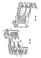
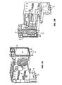
- frame 25 comprises four peripheral subassembly bays 27, and a power supply bay 29 including an integral finger guard 26. Finger guard 26 aids in preventing a user or technician from inadvertently contacting a fan blade (not shown) within a power supply subassembly mounted within bay 29 (as shown in Figures 9a-b below), when the computer enclosure is opened for service.
- frame 25 comprises a plurality of circuit board retaining snaps 30 and a boss 31 to locate and secure a main processor board, as will be discussed in connection with Figure 7 below).
- Each of the subassembly bays 27 further includes an integrally-formed subassembly retaining snap 28 having a latch head 28a designed to mate with and secure peripheral subassemblies (not shown) within bays 27 and 29 , discussed in more detail below in connection with Figures 7-9.
- frame 25 Also formed in front and rear portions of frame 25 are a plurality of cruciforms 32, a plurality of frame-mounting snaps 33, and a plurality of frame-mounting openings 34. whose collective function is to secure frame 25 to base 10.
- Cruciforms 32, snaps 33, and openings 34 are designed to be respectively received by cruciform-locating openings 23 at the front of base 10 and in the frame support member 20 at the rear of base 10 ( Figure 1 ), the frame-mounting openings 24 in the frame support member 20 ( Figure 1 ), and the upwardly extending frame-mounting snaps 22 located at the front portion of base 10 ( Figure 1 ).
- frame 25 includes a plurality of panel-mounting openings 26 located at the upper rear of frame 25, whose function will be described in Figure 5a below.
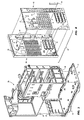
- frame 25 is first aligned above base 10 in conformance with all front and rear positioning and locking features (e.g., cruciforms 32 and cruciform-locating openings 23), and then lowered down onto base 10 such that positioning and locking features are mated and seated.
- cruciforms 32 at the front and rear of frame 25 will seat within cruciform-locating openings 23 at the front and rear of base 10, and frame-mounting snaps 33 on frame 25 will be received by frame-mounting openings 24 located in the frame support member 20 of base 10 ( Figure 1 ).
- frame-mounting snaps 22 at the front portion of base 10 will be received by the frame-mounting openings 34 at the front of frame 25 ( Figure 1).
- a rear panel 38 is illustrated having a numerosity of pin members 39 distributed over the interior surface 38a of panel 38.
- Rear panel 38 also comprises a plurality of panel-mounting snaps 36 and hooks 37 as shown. Snaps 36 and hooks 37 will be used to secure panel 38 to base 10 and frame 25 in substantially the same manner as securing frame 25 to base 10, as will be shown in Figure 5a below.
- a rear EMI shield 40 having, among other features, a plurality of snap-passthroughs 41 and through-holes 42 corresponding in number and location to pin members 39.
- rear panel assembly 46 is obliquely positioned against the rearward facing surfaces of the prior-assembled base 10 and frame 25 such that hooks 37 on assembly 46 engage in hook-receiving openings 9 in base 10.
- Assembly 46 is thereafter rotated vertically about a horizontal axis extending through hooks 37 until it snugly bears against the rearward facing surfaces of base 10 and frame 25, whereby panel-mounting snaps 36 are received into panel-mounting openings 26 in frame 25.
- gentle pressure is applied to assembly 46 until snaps 36 are positively engaged to retain assembly 46 on base 10 and frame 25.
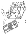
- base 10, frame 25, and rear panel assembly 46 together comprise a base-frame assembly 10' illustrated in Figure 5b, to which may be now added a multiplicity of prior-assembled functional subassemblies, as shown and discussed in the following figures.
- a modular speaker housing 49 may be positioned within an appropriate space on frame 25, and locked into place.
- FIG. 6a-c wherein are illustrated preparatory steps in forming a main circuit board subassembly 50, consisting illustratively of a main printed circuit board (PCB) 51 , to which is attached a PCB protector 52 using a hook and snap attachment means fundamentally similar to that employed in attaching rear panel assembly 46 to base 10 and frame 25.
- PCB protector 52 will be seen more clearly in Figure 16b, wherein protector 52 guards main PCB 51 against damage when a top cover assembly, also discussed in connection with Figures 15-16, is lowered down upon base-frame assembly 10' when assembly thereof is substantially complete.
- Main cable bundle 53 may be formed in any manner and size appropriate to the wiring requirements of the computer system being constructed.
- cable bundle 53 may provide power and signal connection for floppy and fixed-head disk drives, Small Computer Serial Interface (SCSI) devices, and other devices by providing appropriate connectors 55 at various points in the cable bundle, as is generally known.
- Main cable bundle 53 will be routed to various subassemblies mounted within the interior portions of frame 25, and will be shown in greater detail in Figures 10a-b below.
- Additional wiring needs can be accommodated by providing and routing one or more secondary cable bundles between particular subassemblies, as for example direct power connection between the main processor board 51 and a power supply subassembly 35 (shown below), as suggested by secondary cables 57a and 57b in Figure 6c.
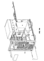
- main processor board assembly 50 being mounted vertically to one side of base-frame assembly 10'.
- assembly 50 is first obliquely positioned received into and located by a first plurality of board guides 58 (comprising substantially grooved bosses) formed in a vertical line in rear panel assembly 46, and then pivoted about a vertical axis running through board guides 58 such that assembly 50 is received by the second plurality of board guides 59 formed in base 10, substantially as shown.
- Main processor board assembly 50 is then secured to base-frame assembly 10' by engaging circuit board retaining snaps 30 of frame 25 into appropriate openings in main processor board assembly 50, and then driving a threaded fastener into boss 31 in frame 25.
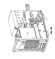
- any number of desired peripheral subassemblies 60 may be inserted in the respective bays 27, and rammed home, each subassembly thereby engaging a latch head 28a on the respective subassembly retaining snap 28.
- peripheral subassemblies 60 may require prior mounting to a carrier 62 before being inserted in bays 27.
- carriers 62 should be designed to receive latch heads 28a of retaining snaps 28.
- a power supply module 35 having a plurality of L-shaped tabs 66a is inserted into the power supply bay 29 such that the L-shaped tabs 66a are received by a corresponding plurality of keyways 66b, as shown.
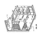
- Power supply module 35 is then urged rearward as suggested by arrows 68 until a power supply retaining snap 69, not visible in Figure 9a but shown in Figures 2a and 2c-d, is deflected laterally as power supply module 35 moves past it, power supply retaining snap 69 snapping in place behind power supply module 35 and locking it in place. Thereafter, additional support structures may be snapped into place using the hook-and-snap scheme employed in connection with other subassemblies. Shown in Figure 9b is a bracket 70, added to provide support for optional peripheral circuit boards (not shown) to be mounted within base-frame assembly 10' and operating on any of a variety of internal bus architectures, such as that defined by the NuBus® protocol.
- FIGS 10a-b are shown completion of the steps of connecting the connectors 55 of main cable bundle 53 to the several subassemblies 60 mounted in base-frame assembly 10'.
- secondary, direct wiring requirements may be fulfilled by routing secondary cables 57a and 57b between appropriate devices.
- front panel 76 is formed substantially similar to rear panel 38, wherein front panel 76 is configured to receive a front EMI shield 77, which shield 77 is subsequently mounted and secured to panel 76 to form a front panel assembly 78.
- front panel 76 may comprise a plurality of upwardly extending posts 78 intended to reciprocally receive a plurality of self-clinching tanged openings 79 formed in front EMI shield 77, as shown.
- front panel 76 and shield 77 together may comprise a system of pin members and through-holes, as employed in the rear panel assembly 46 shown in Figure 4 above.
- Front panel 76 also comprises a plurality of panel-mounting hooks 80 and snaps 81 as shown, which hooks 80 and snaps 81 will be used to secure front panel assembly 78 to a conformal U-shaped top cover 90 (shown in connection with Figures 12a-b and described immediately below), in substantially the same manner as securing rear panel assembly 46 to base-frame assembly 10' described in Figure 5a above.
- top cover 90 is formed in any generally known manner to enclose base-frame assembly 10'.
- Top cover 90 may be formed of any suitable material, but in a preferred embodiment comprises an electrically conductive, metallic cover to ensure sufficient shielding for EMI-reduction purposes.
- Front panel assembly 78 is subsequently obliquely positioned against frontward facing surfaces 91 of top cover 90 such that hooks 80 on assembly 78 engage in hook-receiving openings 93 in top cover 90.
- Assembly 78 is thereafter rotated about a vertical axis extending through hooks 80 until assembly 78 snugly bears against the balance of the frontward facing surfaces 91 of top cover 90, whereby panel-mounting snaps 81 are received into panel-mounting openings in top cover 90.
- gentle pressure may then be applied to assembly 78 until snaps 81 are positively engaged to retain assembly 78 on cover 90.
- cantilever snaps as just described, or as employed in mounting rear panel assembly 46 above.
- a plurality of tab members 95 having through-holes 96 may be formed in cover 90 adjacent to frontward facing surfaces 91.
- front panel assembly may comprise a corresponding plurality of posts (not shown), which abut to tab members 95 and which receive thread-forming fasteners 98 to secure assembly 78 to cover 90.
- fasteners 98 may, as in the preferred embodiment, comprise Torx® high strength screws.
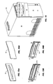
- Figures 13a-b are respectively shown front and rear perspective views of a first embodiment of a bezel 85 designed to conformally cover openings in front panel 76 through which removable mass storage media are passed to mass storage subassemblies installed in bays 27 (Figure 8 above).
- Figures 14a-b are shown front and rear perspective views of an alternative embodiment of a bezel 85' designed to conformally cover openings in front panel 76 through which no mass storage media are to be passed, there being, for example, a fixed-head disk drive subassembly installed in the corresponding bay 27.
- pairs of hooks 86 and snaps 87 are employed to engage and secure combinations of bezels 85 and 85' to front panel assembly 78 mounted to cover 90, in the fashion of front and rear panel assemblies 46 and 78, as suggested in Figure 15.
- Appropriate EMI shielding may be attached to interior surfaces of bezels 85 or 85' as necessary to reduce emitted EMI.
- front panel assembly mated to cover 90 comprises a detachable, top cover assembly 100.
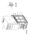
- top cover assembly 100 is first positioned substantially over base-frame assembly 10', and then lowered upon it, as shown.
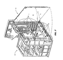
- PCB protector 52 can be seen to guard against inadvertent damage to the main circuit board 51 by having vertically extending rib members 105 deflect the lateral sides of top cover assembly 100 away from board 51 as cover assembly 100 is lowered, as suggested by the cut-away detail in Figure 16b.
- cover assembly has been lowered into substantially its final position, the lower surfaces of top cover 90 will bear upon the hemispherical domes 18 on tabbed fingers 17 of base EMI shield 15 ( Figure 1b above).
- top cover assembly 100 effectively completes the EMI shielding structure for the computer system when assembly 100 makes contact with base shield 15 and rear shield 40. Thereafter, top cover assembly 100 is slideably moved rearward upon a pair of inclined standoffs until the rear edges of assembly 100 contact a plurality of contact fingers (not shown) formed in the rear EMI shield 40, the top cover assembly 100 resting upon on the dome-like structures 18 of the base EMI shield fingers 17.
- the top cover assembly may then be securely fastened to the built up base-frame assembly 10' by driving conventional thumbscrews through the rear panel assembly 46 into complementary threaded through-holes (not shown) in the rear flange of the top cover 90, and by a lower edge of the front panel bearing against an extended lip formed in the front portion of base-frame assembly 10'.
- the modularity of the base-frame assembly 10' permits a user or service technician to easily access, remove and replace any functional subsystem without need for substantial disassembly of the computer system. Rather, having removed the top cover assembly 100, any subassembly 60 can replaced independently. For example, power supply subassembly 35 can be removed in the event of failure or upgrade without affecting any of the frontally mounted subassemblies 60.
- a computer manufacturer assembling products in accordance with the above invention can more easily incorporate the latest system technologies, without requiring substantial modifications or refabrication of existing inventory of enclosures.
- a manufacturer of products incorporating the present invention can simply remove the top cover assembly, remove the individual subassembly being updated, and reinstall the cover. For example, if main circuit board 50 undergoes a processor upgrade, a technician must only open the computer remove the existing circuit board, and install the new main circuit board 50 independent of the other subassemblies, thus saving time and costs.
Landscapes
- Engineering & Computer Science (AREA)
- Theoretical Computer Science (AREA)
- Physics & Mathematics (AREA)
- Human Computer Interaction (AREA)
- General Engineering & Computer Science (AREA)
- General Physics & Mathematics (AREA)
- Power Engineering (AREA)
- Computer Hardware Design (AREA)
- Electromagnetism (AREA)
- Shielding Devices Or Components To Electric Or Magnetic Fields (AREA)
Abstract
Description
- The present invention relates generally to computer enclosure construction designs and methods. More particularly, the present invention relates to a personal computer enclosure designed to be assembled and to receive modular subassembly components substantially with minimal fasteners or other assembly hardware.
- Computer systems typically comprise numerous electronic and mechanical components and subsystems coupled together to function as a unit. For example, a common arrangement of component subparts forming a personal computer system might include a central processor unit (CPU), memory devices, and input and output (I/O) controllers coupled to a main processor board, with other peripheral devices (e.g., floppy, hard, or optical mass storage drives) and functional subassemblies (e.g., power supplies) mounted elsewhere within a housing or enclosure. The various peripheral and functional subsystems of the personal computer are connected to each other by wiring or other communication pathways.
- In the prior art, the above subassemblies typically are installed into computer enclosures using straightforward mounting methods and hardware, including screws, damps, rivets, and brackets. The computer housing itself frequently may comprise a substantially rectangular metal or plastic housing having threaded through-holes or spot-welded brackets and standoffs positioned to receive the above subassemblies. Frequently the mechanical strength of the enclosure is obtained by providing a metal chassis to receive and support the subassemblies, and mounting a plastic shell over the chassis to provide attractive cosmetics and finish. In such a case, subassemblies must be fastened onto the metal chassis with the above hardware using hand or machine tools. Additionally, large metal chassis may entail higher material costs and greater weight than comparable plastic parts.
- Especially in the rapidly evolving field of personal computers, modularity and interchangeability of system subassemblies is of great importance to manufacturers, retailers, and users alike. In the case of a manufacturer, modularity is important because the manufacturer can more easily and cost effectively adapt to customer demands and technology changes without substantially redesigning or rebuilding existing products. Moreover, products can be more easily built at a central manufacturing site, and then customized for localized domestic and foreign use. Alternatively, a retailer can more easily update stocked but unsold computer systems as more powerful subassemblies become available, or to upgrade and service customers' computer systems. Customers benefit from modular system designs because they initially can purchase a base system which meets their present needs, and later expand their systems' performance and storage functions by replacing components to achieve higher performance. For example, a customer may wish to replace his existing processor board with a more powerful processor board, or to replace an existing disk drive with a higher capacity mass storage device, but without requiring a dealer or other service person to perform the upgrade.
- Although prior art computer system designs may have included some modularity in that processor boards and mass storage devices could be replaced, such replacement typically requires that many of the subassemblies, especially those mounted near the top of the computer enclosure be removed to gain access to the lower mounted subassemblies. As a result, a substantial portion of any prior art computer system would have to be disassembled to install a new subassembly. For a manufacturer seeking to upgrade finished goods with a newly available product, such disassembly and reassembly can substantially increase labor costs, and therefore the final cost of the computer system.
- As will be described in the following detailed description, the present invention overcomes many of the problems associated with prior art personal computer system enclosures by providing a simple, light weight yet robust, design comprising essentially five parts which can be substantially snapped together, and which uses only minimal traditional hardware elements. The enclosure is designed to receive all functional components and subassemblies necessary to the operation of a personal computer system without limiting access to any other subassembly. As a result, a personal computer system designed and assembled in accordance with the present invention can be easily and inexpensively reconfigured and updated by the manufacturer, retailer, or end user without need for time consuming disassembly and assembly operations.
- A modular enclosure for personal computer systems, and methods for assembly of an enclosure, are disclosed and set forth in the claims appended hereto.
- In one embodiment, the enclosure substantially comprises a base, an internal frame, a front and a back panel, and a U-shaped top cover. The internal frame comprises a single piece plastic molding with appropriately formed bays designed to receive various system subassemblies, such as floppy disk drives, hard disk drives and the like. Each bay has an integrally formed flexible snap having a latch head to bear against and retain a subassembly placed in the bay. The base also has a plurality of frame-mounting snaps and cruciform members located on forward and rear portions of the frame which mate to complimentary receiving openings in the base. The front and rear panels have a plurality of panel-mounting snaps and hooks which are received by mating openings in the base, frame and top cover respectively.
- A base electromagnetic interference (EMI) shield is then fitted and secured to the base. The base EMI shield comprises a plurality of planar tabbed fingers formed in the periphery of the shield, each finger having a hemispherical dome centrally disposed between lateral edges of each finger. The base EMI shield is attached to the base such that the lateral edges of the fingers are conformal to and recessed below a peripherally extending rim on the base. Thereafter the internal frame is located above, and snapped into place upon, the front and rear portions of the base. Thereafter, a rear EMI shield is fitted and secured to the back panel, and the panel maneuvered into position and secured the base and frame by the panel-mounting snaps and hooks.
- A plurality of subassemblies, including disk drives, optical disk drives, power supplies, main processor printed circuit boards, and speaker housings are then placed into the respective bays and secured via a plurality of subassembly retaining snaps, guides, tabs, and other interlocking members. Electrical connection for the computer system is substantially established by routing an appropriately sized main cable bundle between the subassemblies, and connecting each subassembly to terminal ends of the cable bundle via a plurality of connectors. Additional wiring needs can be accommodated by providing and routing one or more secondary cable bundles between particular subassemblies, as for example between the main processor board and the speaker housing.
- A front EMI shield is then secured to the front panel, and the panel maneuvered into a dosed position relative to the rear of the U-shaped top cover via hooks formed on one lateral edge of the panel. The front panel is secured to the top cover by panel-mounting snaps formed on the opposing lateral edge mating to receiving openings in the top cover, thereby forming a four-sided top cover assembly. One or more bezels is detachably mounted to the front panel via hooks and snaps to permit access to the subassembly devices frontally mounted in the bays of the built up base-frame assembly. Each bezel may be fitted with EMI shielding as necessary to mate to the subassembly housing or the front EMI shield to effect a continuous EMI shield at the front portion of the computer system.
- Finally, the top cover is lowered onto and slideably moved rearward upon a pair of inclined standoffs until the rear edges of the top cover assembly contact a plurality of contact fingers formed in the rear EMI shield, the top cover assembly resting upon on the dome-like structures of the base EMI shield fitted to the base-frame assembly. The top cover assembly is securely fastened to the built up base-frame assembly by conventional thumbscrews extending through the rear panel into complementary threaded through-holes in the rear flange of the top cover assembly, and by a lower edge of the front panel bearing against an extended lip formed in the front portion of the base.
- The present invention will be understood more fully from the detailed description given below and from the accompanying drawings of the preferred embodiment of the invention in which:
- Figures 1a-c are perspective views of the formation of a base assembly of a personal computer enclosure.
- Figures 2a-d are perspective views of an internal frame
- Figure 3 illustrates mounting the frame to the base assembly.
- Figures 4 illustrates the formation of a rear panel assembly.
- Figures 5a-b illustrates mounting the rear panel assembly to the base and frame to form a base-frame assembly.
- Figures 6a-c illustrate the formation of a main circuit board assembly.
- Figure 7 shows the mounting of the main board assembly to the base-frame assembly.
- Figure 8 illustrates installation of modular subassemblies within the base-frame assembly.
- Figures 9a-b further illustrate installation of modular subassemblies within the base-frame assembly.
- Figures 10a-b illustrate the installation of main and secondary cable assemblies within the base-frame assembly.
- Figure 11 illustrates the formation of a front panel assembly.
- Figures 12a-b illustrate the installation of a top cover assembly.
- Figures 13a-b illustrate a first embodiment of a bezel.
- Figures 14a-b illustrate a second, alternative embodiment of a bezel.
- Figure 15 illustrates the installation of bezels into the front panel assembly.
- Figure 16 illustrates the installation of the top cover assembly onto the base-frame assembly, completing the computer enclosure.
-
- The present invention discloses a modular enclosure for personal computer systems, and methods for assembly of such an enclosure. In the following description, for purposes of explanation, specific numbers, dimensions, and configurations are set forth in order to provide a thorough understanding of the present invention. However, it will be apparent to one skilled in the art that the present invention may be practiced without these specific details. In other instances, well known systems are shown in diagrammatical or block diagram form in order not to obscure the present invention unnecessarily.
- Reference is now made to Figure 1, wherein is illustrated a perspective view of a
base 10, forming a portion of the present invention.Base 10 comprises a raised floor 11, aperiphery 16, and a plurality of upwardly extending posts 12, where posts 12 reciprocally receive a plurality of self-clinchingtanged openings 14 formed in a base electromagnetic interference (EMI)shield 15. It is anticipated that, according to the present invention,base 10 will comprise a molded plastic part, and thatbase EMI shield 15 may be formed of any thin, conductive, spring-steel material as is generally known, for example 0.020" nickel plated carbon steel shim stock.Base EMI shield 15 further comprises a plurality of planar, tabbedfingers 17 formed in peripheral edges of theshield 15, eachfinger 17 having a one or morehemispherical domes 18 proportionally disposed betweenlateral edges 19 of eachfinger 17, as more clearly shown in Figure 1b.Fingers 17 are formed so as to conformally follow the outline ofperiphery 16 ofbase 10. Thereafter, shield 15 is positioned overbase 10 and pressed into place such that posts 12 are received bytanged openings 14, the tang portions ofopenings 14 bearing against and gripping posts 12. In the preferred embodiment of the present invention, raised floor 11 is formed to positionshield 15 at a specified height below the upper edge ofperiphery 16 such that the lateral edges 19 of eachfinger 17 remain recessed below the upper edges ofperiphery 16 ofbase 10. A principal advantage of formingbase shield 15 in the above manner is that the lateral edges 19 of the thin shield material, which may be sharp, are not exposed when a top cover assembly (discussed in connection with Figure 16 below) is removed from the computer enclosure. Risk of injury to the user or to an individual servicing the computer is thereby significantly reduced. Moreover, because lateral edges 19 of theEMI shield 15 are recessed, damage to shield 15 can be avoided when mounting or demounting the top cover becauseedges 19 are not exposed. -
Base 10 further comprises an upwardly extendingframe support member 20 and a plurality of panel-mounting openings 21 located at the rear portion ofbase 10.Base 10 also includes plurality of upwardly extending frame-mountingsnaps 22 disposed at the front portion ofbase 10, as well as a plurality of cruciform-locatingopenings 23 positioned at the front ofbase 10 and in theframe support member 20 at the rear ofbase 10. In addition,base 10 also includes a plurality of frame-mountingopenings 24 in theframe support member 20 substantially as shown. Further, at the rear portion ofperiphery 16 ofbase 10 are provided a plurality of hook-receivingopenings 9 designed to receive and retain a plurality of panel-mounting hooks 37 (referred to and discussed in more detail in connection with Figure 4 below). - Referring now to Figures 2a-2d, perspective views of a single-piece
internal frame 25 are shown. It is intended thatframe 25 function both as an internal chassis to which any number of subassemblies may be mounted in accordance with the teachings of the present invention discussed below, and also as a structural skeleton which imparts strength and rigidity to the entire computer housing when fully assembled. As preferred,frame 25 comprises a single, injection-molded plastic part formed of glass filled polycarbonate-ABS blend plastic. Although thematerial forming frame 25 possesses only a poor cosmetic finish, the glass filled particles within the glass filled polycarbonate-ABS blend plastic provides for greatly increased bending and torsional rigidity relative to ordinary ABS plastic. In addition,frame 25 constructed in accordance with the above material permits a considerable weight saving over that of a conventional metal chassis. - It should be noted that
frame 25 may be dimensionally formed in any manner to receive the desired size and number of peripheral and functional subassemblies. As presently preferred,frame 25 comprises fourperipheral subassembly bays 27, and apower supply bay 29 including anintegral finger guard 26.Finger guard 26 aids in preventing a user or technician from inadvertently contacting a fan blade (not shown) within a power supply subassembly mounted within bay 29 (as shown in Figures 9a-b below), when the computer enclosure is opened for service. In addition,frame 25 comprises a plurality of circuit board retaining snaps 30 and aboss 31 to locate and secure a main processor board, as will be discussed in connection with Figure 7 below). Each of thesubassembly bays 27 further includes an integrally-formedsubassembly retaining snap 28 having alatch head 28a designed to mate with and secure peripheral subassemblies (not shown) withinbays - Also formed in front and rear portions of
frame 25 are a plurality ofcruciforms 32, a plurality of frame-mountingsnaps 33, and a plurality of frame-mountingopenings 34. whose collective function is to secureframe 25 tobase 10.Cruciforms 32, snaps 33, andopenings 34 are designed to be respectively received by cruciform-locatingopenings 23 at the front ofbase 10 and in theframe support member 20 at the rear of base 10 (Figure 1), the frame-mountingopenings 24 in the frame support member 20 (Figure 1), and the upwardly extending frame-mountingsnaps 22 located at the front portion of base 10 (Figure 1). Moreover,frame 25 includes a plurality of panel-mountingopenings 26 located at the upper rear offrame 25, whose function will be described in Figure 5a below. - Reference is now made to Figure 3, wherein assembly of the
frame 25 tobase 10 is illustrated. Having formedframe 25 substantially as described above,frame 25 is first aligned abovebase 10 in conformance with all front and rear positioning and locking features (e.g., cruciforms 32 and cruciform-locating openings 23), and then lowered down ontobase 10 such that positioning and locking features are mated and seated. In particular,cruciforms 32 at the front and rear offrame 25 will seat within cruciform-locatingopenings 23 at the front and rear ofbase 10, and frame-mountingsnaps 33 onframe 25 will be received by frame-mountingopenings 24 located in theframe support member 20 of base 10 (Figure 1). Similarly, frame-mountingsnaps 22 at the front portion ofbase 10 will be received by the frame-mountingopenings 34 at the front of frame 25 (Figure 1). - Referring now to Figure 4, a
rear panel 38 is illustrated having a numerosity ofpin members 39 distributed over the interior surface 38a ofpanel 38.Rear panel 38 also comprises a plurality of panel-mountingsnaps 36 and hooks 37 as shown.Snaps 36 and hooks 37 will be used to securepanel 38 tobase 10 andframe 25 in substantially the same manner as securingframe 25 tobase 10, as will be shown in Figure 5a below. Also shown in Figure 4 is arear EMI shield 40, having, among other features, a plurality of snap-passthroughs 41 and through-holes 42 corresponding in number and location to pinmembers 39. When maneuvered into position relative torear panel 38, through-holes 42 ofrear shield 40 receivepin members 39, shield 40 seating upon a plurality ofstandoffs 45 disposed on interior surface 38a at a chosen distance. Having positionedrear shield 40 ontorear panel 38,pin members 39 are heat-staked in accordance with generally known plastics forming methods to form rivet-like structures to securely retainshield 40 againststandoffs 45panel 38, thereby forming arear panel assembly 46. When thus assembled, panel-mountingsnaps 36 extend freely through snap-passthroughs 41 so as to permit mountingassembly 46 tobase 10 andframe 25, as will be discussed immediately below. As necessary, pieces of electricallyconductive foam 44 may be placed betweenshield 40 andpanel 38 to enhance EMI shielding qualities ofrear panel assembly 46. - With reference now to Figures 5a-b,
rear panel assembly 46 is obliquely positioned against the rearward facing surfaces of the prior-assembledbase 10 andframe 25 such that hooks 37 onassembly 46 engage in hook-receivingopenings 9 inbase 10.Assembly 46 is thereafter rotated vertically about a horizontal axis extending throughhooks 37 until it snugly bears against the rearward facing surfaces ofbase 10 andframe 25, whereby panel-mountingsnaps 36 are received into panel-mountingopenings 26 inframe 25. Once received withinopenings 26, gentle pressure is applied toassembly 46 untilsnaps 36 are positively engaged to retainassembly 46 onbase 10 andframe 25. Thus assembled,base 10,frame 25, andrear panel assembly 46 together comprise a base-frame assembly 10' illustrated in Figure 5b, to which may be now added a multiplicity of prior-assembled functional subassemblies, as shown and discussed in the following figures. For example, as shown in Figures 5a-b, amodular speaker housing 49 may be positioned within an appropriate space onframe 25, and locked into place. - Reference is now made to Figures 6a-c, wherein are illustrated preparatory steps in forming a main
circuit board subassembly 50, consisting illustratively of a main printed circuit board (PCB) 51, to which is attached aPCB protector 52 using a hook and snap attachment means fundamentally similar to that employed in attachingrear panel assembly 46 tobase 10 andframe 25. The purpose ofPCB protector 52 will be seen more clearly in Figure 16b, whereinprotector 52 guardsmain PCB 51 against damage when a top cover assembly, also discussed in connection with Figures 15-16, is lowered down upon base-frame assembly 10' when assembly thereof is substantially complete. Next, as shown in Figure 6b, provision for electrical connection to all functional subsystems within the computer system is made by coupling an appropriately sizedmain cable bundle 53 to a main connector block 54 onmain PCB 51.Main cable bundle 53 may be formed in any manner and size appropriate to the wiring requirements of the computer system being constructed. For example in Figure 6b,cable bundle 53 may provide power and signal connection for floppy and fixed-head disk drives, Small Computer Serial Interface (SCSI) devices, and other devices by providingappropriate connectors 55 at various points in the cable bundle, as is generally known.Main cable bundle 53 will be routed to various subassemblies mounted within the interior portions offrame 25, and will be shown in greater detail in Figures 10a-b below. Additional wiring needs can be accommodated by providing and routing one or more secondary cable bundles between particular subassemblies, as for example direct power connection between themain processor board 51 and a power supply subassembly 35 (shown below), as suggested bysecondary cables - In Figure 7 is shown main
processor board assembly 50 being mounted vertically to one side of base-frame assembly 10'. In Figure 7,assembly 50 is first obliquely positioned received into and located by a first plurality of board guides 58 (comprising substantially grooved bosses) formed in a vertical line inrear panel assembly 46, and then pivoted about a vertical axis running through board guides 58 such thatassembly 50 is received by the second plurality of board guides 59 formed inbase 10, substantially as shown. Mainprocessor board assembly 50 is then secured to base-frame assembly 10' by engaging circuit board retaining snaps 30 offrame 25 into appropriate openings in mainprocessor board assembly 50, and then driving a threaded fastener intoboss 31 inframe 25. - Referring now to Figures 8-10, any number of desired
peripheral subassemblies 60 may be inserted in therespective bays 27, and rammed home, each subassembly thereby engaging alatch head 28a on the respectivesubassembly retaining snap 28. As is generally known,peripheral subassemblies 60 may require prior mounting to acarrier 62 before being inserted inbays 27. In general,carriers 62 should be designed to receivelatch heads 28a of retaining snaps 28. Further, in Figure 9a, apower supply module 35 having a plurality of L-shapedtabs 66a is inserted into thepower supply bay 29 such that the L-shapedtabs 66a are received by a corresponding plurality ofkeyways 66b, as shown.Power supply module 35 is then urged rearward as suggested byarrows 68 until a powersupply retaining snap 69, not visible in Figure 9a but shown in Figures 2a and 2c-d, is deflected laterally aspower supply module 35 moves past it, powersupply retaining snap 69 snapping in place behindpower supply module 35 and locking it in place. Thereafter, additional support structures may be snapped into place using the hook-and-snap scheme employed in connection with other subassemblies. Shown in Figure 9b is abracket 70, added to provide support for optional peripheral circuit boards (not shown) to be mounted within base-frame assembly 10' and operating on any of a variety of internal bus architectures, such as that defined by the NuBus® protocol. Installation and support for such optional peripheral circuit boards must be anticipated in any modern personal computer system. In Figures 10a-b are shown completion of the steps of connecting theconnectors 55 ofmain cable bundle 53 to theseveral subassemblies 60 mounted in base-frame assembly 10'. As suggested above in Figures 6a-c, secondary, direct wiring requirements may be fulfilled by routingsecondary cables - With reference to Figure 11, assembly of a front panel assembly 75 is illustrated. In Figure 11, a
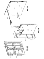
front panel 76 is formed substantially similar torear panel 38, whereinfront panel 76 is configured to receive afront EMI shield 77, whichshield 77 is subsequently mounted and secured topanel 76 to form afront panel assembly 78. Accordingly,front panel 76 may comprise a plurality of upwardly extendingposts 78 intended to reciprocally receive a plurality of self-clinchingtanged openings 79 formed infront EMI shield 77, as shown. Alternatively,front panel 76 andshield 77 together may comprise a system of pin members and through-holes, as employed in therear panel assembly 46 shown in Figure 4 above.Front panel 76 also comprises a plurality of panel-mountinghooks 80 and snaps 81 as shown, which hooks 80 and snaps 81 will be used to securefront panel assembly 78 to a conformal U-shaped top cover 90 (shown in connection with Figures 12a-b and described immediately below), in substantially the same manner as securingrear panel assembly 46 to base-frame assembly 10' described in Figure 5a above. - Referring now to Figures 12a-b, conformal U-shaped
top cover 90 is formed in any generally known manner to enclose base-frame assembly 10'.Top cover 90 may be formed of any suitable material, but in a preferred embodiment comprises an electrically conductive, metallic cover to ensure sufficient shielding for EMI-reduction purposes.Front panel assembly 78 is subsequently obliquely positioned against frontward facing surfaces 91 oftop cover 90 such that hooks 80 onassembly 78 engage in hook-receivingopenings 93 intop cover 90.Assembly 78 is thereafter rotated about a vertical axis extending throughhooks 80 untilassembly 78 snugly bears against the balance of the frontward facing surfaces 91 oftop cover 90, whereby panel-mountingsnaps 81 are received into panel-mounting openings intop cover 90. Gentle pressure may then be applied toassembly 78 untilsnaps 81 are positively engaged to retainassembly 78 oncover 90. Alternatively, due to space limitations, it may not be feasible to employ cantilever snaps as just described, or as employed in mountingrear panel assembly 46 above. In such a case, a plurality oftab members 95 having through-holes 96 may be formed incover 90 adjacent to frontward facing surfaces 91. Further, in lieu ofsnaps 81, front panel assembly may comprise a corresponding plurality of posts (not shown), which abut totab members 95 and which receive thread-formingfasteners 98 to secureassembly 78 to cover 90. Where ruggedness of design warrants,fasteners 98 may, as in the preferred embodiment, comprise Torx® high strength screws. - In Figures 13a-b are respectively shown front and rear perspective views of a first embodiment of a
bezel 85 designed to conformally cover openings infront panel 76 through which removable mass storage media are passed to mass storage subassemblies installed in bays 27 (Figure 8 above). Alternatively, In Figures 14a-b, are shown front and rear perspective views of an alternative embodiment of abezel 85' designed to conformally cover openings infront panel 76 through which no mass storage media are to be passed, there being, for example, a fixed-head disk drive subassembly installed in thecorresponding bay 27. In either case, pairs ofhooks 86 and snaps 87 are employed to engage and secure combinations ofbezels front panel assembly 78 mounted to cover 90, in the fashion of front andrear panel assemblies bezels top cover assembly 100. - With reference to Figures 16a-b, final mounting of
top cover assembly 100 to the built-up base-frame assembly 10' is shown.Top cover assembly 100 is first positioned substantially over base-frame assembly 10', and then lowered upon it, as shown. With brief reference to Figure 16b,PCB protector 52 can be seen to guard against inadvertent damage to themain circuit board 51 by having vertically extendingrib members 105 deflect the lateral sides oftop cover assembly 100 away fromboard 51 ascover assembly 100 is lowered, as suggested by the cut-away detail in Figure 16b. After cover assembly has been lowered into substantially its final position, the lower surfaces oftop cover 90 will bear upon thehemispherical domes 18 on tabbedfingers 17 of base EMI shield 15 (Figure 1b above). Becausefingers 17 follow the outline ofperiphery 16 ofbase 10 to which top cover 90 conforms,top cover assembly 100 effectively completes the EMI shielding structure for the computer system whenassembly 100 makes contact withbase shield 15 andrear shield 40. Thereafter,top cover assembly 100 is slideably moved rearward upon a pair of inclined standoffs until the rear edges ofassembly 100 contact a plurality of contact fingers (not shown) formed in therear EMI shield 40, thetop cover assembly 100 resting upon on the dome-like structures 18 of the baseEMI shield fingers 17. The top cover assembly may then be securely fastened to the built up base-frame assembly 10' by driving conventional thumbscrews through therear panel assembly 46 into complementary threaded through-holes (not shown) in the rear flange of thetop cover 90, and by a lower edge of the front panel bearing against an extended lip formed in the front portion of base-frame assembly 10'. - Having thus described the assembly of a modular personal computer, the benefits of the foregoing design principles will be briefly discussed below. First, the modularity of the base-frame assembly 10' permits a user or service technician to easily access, remove and replace any functional subsystem without need for substantial disassembly of the computer system. Rather, having removed the
top cover assembly 100, anysubassembly 60 can replaced independently. For example,power supply subassembly 35 can be removed in the event of failure or upgrade without affecting any of the frontally mountedsubassemblies 60. Second, a computer manufacturer assembling products in accordance with the above invention can more easily incorporate the latest system technologies, without requiring substantial modifications or refabrication of existing inventory of enclosures. Rather than having to dismantle an assembled system constructed according to the prior art, a manufacturer of products incorporating the present invention can simply remove the top cover assembly, remove the individual subassembly being updated, and reinstall the cover. For example, ifmain circuit board 50 undergoes a processor upgrade, a technician must only open the computer remove the existing circuit board, and install the newmain circuit board 50 independent of the other subassemblies, thus saving time and costs. - The foregoing has described an arrangement for, and methods for assembling, a simple, light weight yet robust modular enclosure for a personal computer system. comprising essentially five snapped together structural pieces. The enclosure is designed to receive all functional components and subassemblies necessary to the operation of a personal computer system without limiting access to any other subassembly. As a result, a personal computer system designed and assembled in accordance with the present invention can be easily and inexpensively reconfigured and updated by the manufacturer, retailer, or end user without need for time consuming disassembly and assembly operations. Although the foregoing has been described in terms of presently preferred and alternate embodiments, those skilled in the art will recognize that the invention is not limited to the embodiments described. The method and apparatus of the present invention can be practiced with modification and alteration within the scope of the appended claims. The description is thus to be regarded as illustrative instead of limiting on the present invention.
Claims (6)
- A modular enclosure for a personal computer system including a main processor board intercommunicating with a plurality of internal peripheral and functional subassemblies, the modular enclosure comprising:a base assembly further comprising:a base (10) comprising a first interior surface having a first plurality of pin members (12) disposed thereon;a base electromagnetic interference (EMI) shield (15) mounted to said base (10), said base EMI shield (15) comprising a first plurality of shield mounting openings (14) receiving and retaining said first plurality of pin members (12);a first plurality of grooved board guides (59) to receive and locate a first edge of said main processor board (50);a first plurality of frame mounting snaps (22),a first plurality of frame mounting openings (24),a first plurality of cruciform receiving openings (23);an upwardly extending frame support member (20) having a second plurality of cruciform receiving openings (23); and,a first plurality of hook receiving openings (9);a unitary, internal frame (25) mounted to said base assembly, said
internal frame (25) comprising:at least one bay (27) designed to receive said internal peripheral and functional subassemblies (60);at least one subassembly retaining snap (28) having a latch head (28a);an integrally formed finger guard;first and second pluralities of cruciforms (32) received and seated in said first and second pluralities of cruciform openings (23) in said base assembly;a second plurality of frame mounting snaps (33) received into said first plurality of frame mounting openings (24) in said base assembly; and,a second plurality of frame mounting openings (34) receiving said first plurality of frame mounting snaps (22) in said base assembly;a rear panel assembly (46) mounted to said base assembly and said
internal frame (25), comprising:a rear panel (38) further comprising a second interior surface (38a) having a second plurality of pin members (39) disposed thereon;a rear EMI shield (40) mounted to said rear panel (38) and comprising a second plurality of shield mounting openings (42) receiving and retaining said second plurality of pin members (39);a first plurality of panel mounting hooks (37) received into said first plurality of hook receiving openings (9) in said base (10); and,a second plurality of grooved board guides (58) to receive and locate a second edge of said main processor board (50); and,a top cover assembly (100) comprising a U-shaped top cover (90) and
a front panel assembly (75), mounted to said base assembly, said internal frame (25), and said rear panel assembly (46):said U-shaped top cover (90) comprising left, right, and top surfaces, and having open front, rear, and bottom regions disposed between said left, right, and top surfaces, said top cover (90) further comprising: a second plurality of hook receiving openings (93); and,a plurality of front panel retaining tabs (95);said front panel assembly (75) comprising:a front panel (76) further comprising a third plurality of pin members (78);a front EMI shield (77) mounted to said front panel (76) and comprising a third plurality of shield mounting openings (79) receiving and retaining said third plurality of pin members (78);a second plurality of panel mounting hooks (80) received into said second plurality of hook openings (93) in said top cover (90); and,a plurality of panel mounting posts (81), received and retained against said front panel retaining tabs (95), on said front panel assembly (75). - The enclosure system as set forth in claim 1, wherein said base EMI shield (15) comprises:a main shield portion; and,a shield periphery laterally bounding said main shield portion and comprising a plurality of tabbed fingers (17) coplanar with and extending outward from said main portion, said tabbed fingers (17) further comprising a top side with at least one hemispherical dome structure (18) disposed thereon.
- The enclosure system as set forth in claim 2, wherein the base (10) further comprises:said top cover assembly (100) riding on said hemispherical domes (18) when said top cover assembly (100) is mounted to said base, frame (25), and panel (46) assemblies.a raised floor (11) extending substantially over said first interior surface and substantially receiving said main shield portion of said base EMI shield (15); and,a base periphery (16) extending circumferentially around said raised floor (11) and having a rim, said base periphery (16) substantially comprising a recessed groove to receive said plurality of tabbed fingers (17) such that said top sides and hemispherical domes (18) are disposed in said base periphery (16) below said rim,
- A method for assembling a modular enclosure for a personal computer system including a main processor board intercommunicating with a plurality of internal peripheral and functional subassemblies, the method comprising the steps of:providing a base assembly comprising:a base (10) comprising a first interior surface having a first plurality of pin members (12) disposed thereon;mounting to said base (10) a base electromagnetic interference (EMI) shield (15) comprising a first plurality of shield mounting openings (14) receiving and retaining said first plurality of pin members (12);receiving and locating a first edge of said main processor board (50) by a first plurality of grooved board guides (59);providing first pluralities of frame mounting snaps (22), frame mounting openings (24), hook receiving openings (9), and cruciform receiving openings (23), andforming an upwardly extending frame support member (20) having a second plurality of cruciform receiving openings (23);mounting to said base (10) a unitary, internal frame (25) comprising at least one bay (27) designed to receive said internal peripheral and functional subassemblies (60), and at least one subassembly retaining snap (28) having a latch head (28a); forming an integrally formed finger guard;providing first and second pluralities of cruciforms (32) for receiving and seating in said first and second pluralities of cruciform openings (23) in said base assembly;providing a second plurality of frame mounting snaps (33) to be received into said first plurality of frame mounting openings (24) in said base assembly; and,providing a second plurality of frame mounting openings (34) for receiving said first plurality of frame mounting snaps (22) in said base assembly;mounting, to said base assembly and said internal frame (25), a rear panel assembly (46) comprising a rear panel (38) having a second interior surface (38a) including a second plurality of pin members (39) disposed thereon;mounting, to said rear panel (38), a rear EMI shield (40) comprising a second plurality of shield mounting openings (42) receiving and retaining said second plurality of pin members (39);receiving a first plurality of panel mounting hooks (37) into said first plurality of hook receiving openings (9) in said base (10); and,locating a second edge of said main processor board (50) within a second plurality of grooved board guides (58); and,mounting, to said base assembly, internal frame (25), and rear panel (46) assemblies, a top cover assembly (100) comprising a U-shaped top cover (90) and a front panel assembly (75);providing, on said U-shaped top cover (90), left, right, and top surfaces, and providing further open front, rear, and bottom regions disposed between said left, right, and top surfaces;providing further, on said U-shaped top cover (90), a second plurality of hook receiving openings (93) and a plurality of front panel retaining tabs (95);providing, on said front panel assembly (75), a front panel (76) further comprising a third plurality of pin members (78);providing further a front EMI shield (77) mounted to said front panel (76) and comprising a third plurality of shield mounting openings (79) receiving and retaining said third plurality of pin members (78);receiving a second plurality of panel mounting hooks (80) into said second plurality of hook openings (93) in said top cover (90); and,receiving and retaining a plurality of panel mounting posts (81), disposed on said front panel (76), against said front panel retaining tabs (95).
- The method as set forth in claim 4, further comprising the steps of:forming, in said base EMI shield (15), a main shield portion and a shield periphery laterally bounding said main shield portion andproviding a plurality of tabbed fingers (17) coplanar with and extending outward from said main shield portion, said tabbed fingers (17) further comprising a top side with at least one hemispherical dome structure (18) disposed thereon.
- The method as set forth in claim 5, further comprising the steps of:extending a raised floor (11) substantially over said first interior surface and substantially receiving said main shield portion of said base EMI shield (15);extending a base periphery (16) having a rim circumferentially around said raised floor (11) to substantially form a recessed groove, and,receiving said plurality of tabbed fingers (17) such that said top sides and hemispherical domes (18) are disposed in said base periphery (16) below said rim, said top cover assembly (100) riding on said hemispherical domes (18) when said top cover assembly (100) is mounted to said base, frame (25), and panel (46) assemblies.
Applications Claiming Priority (3)
| Application Number | Priority Date | Filing Date | Title |
|---|---|---|---|
| US14983 | 1993-02-08 | ||
| US08/014,983 US5349132A (en) | 1993-02-08 | 1993-02-08 | Methods and apparatus for modular computer construction |
| PCT/US1994/001380 WO1994018618A1 (en) | 1993-02-08 | 1994-02-07 | Methods and apparatus for modular computer construction |
Publications (2)
| Publication Number | Publication Date |
|---|---|
| EP0682787A1 EP0682787A1 (en) | 1995-11-22 |
| EP0682787B1 true EP0682787B1 (en) | 2001-09-12 |
Family
ID=21768909
Family Applications (1)
| Application Number | Title | Priority Date | Filing Date |
|---|---|---|---|
| EP94909566A Expired - Lifetime EP0682787B1 (en) | 1993-02-08 | 1994-02-07 | Methods and apparatus for modular computer construction |
Country Status (8)
| Country | Link |
|---|---|
| US (1) | US5349132A (en) |
| EP (1) | EP0682787B1 (en) |
| JP (1) | JPH08508832A (en) |
| KR (1) | KR960701395A (en) |
| AU (1) | AU6236994A (en) |
| CA (1) | CA2154769A1 (en) |
| DE (1) | DE69428270D1 (en) |
| WO (1) | WO1994018618A1 (en) |
Families Citing this family (49)
| Publication number | Priority date | Publication date | Assignee | Title |
|---|---|---|---|---|
| US5587877A (en) * | 1994-10-26 | 1996-12-24 | Amco Engineering Co. | Computer organizer enclosure and method |
| DE9418448U1 (en) * | 1994-11-18 | 1995-01-12 | Schroff Gmbh, 75334 Straubenhardt | Rack for a device cabinet |
| US5657202A (en) * | 1996-01-31 | 1997-08-12 | Ma; Hsi-Kuang | Combination of computer mainframe housing, sound producing unit, and mainframe unit |
| US5808863A (en) * | 1996-12-10 | 1998-09-15 | Dell U.S.A., L.P. | Computer system having quick-detachable recyclable parts and method |
| US5999416A (en) * | 1996-12-20 | 1999-12-07 | Dell Computer Corporation | Cover/shield assembly for electronic components |
| KR200200857Y1 (en) * | 1997-03-05 | 2000-11-01 | 윤종용 | Display apparatus for shield structure |
| US5870284A (en) * | 1997-03-17 | 1999-02-09 | Astec International Limited | Integrated power supply frame including integrated circuit (IC) mounting and cooling |
| US5901038A (en) * | 1997-03-17 | 1999-05-04 | Cheng; Wing Ling | Power supply system for high density printed circuit boards |
| US6130822A (en) * | 1997-06-09 | 2000-10-10 | Compaq Computer Corporation | Pivotable computer access door structure having concealed, Break-away hinge mechanism |
| US5872332A (en) * | 1997-06-27 | 1999-02-16 | Delco Electronics Corp. | Molded housing with EMI shield |
| US5884988A (en) * | 1997-07-08 | 1999-03-23 | Sun Microsystems, Inc. | Toner-type computer housing for peripherals |
| US5867369A (en) * | 1997-07-15 | 1999-02-02 | Sun Microsystems, Inc. | Rugged computer housing |
| US6157547A (en) * | 1998-05-28 | 2000-12-05 | 3Com Corporation | Electromagnetic interference shielding filter apparatus and method |
| US5964513A (en) * | 1998-05-28 | 1999-10-12 | Intel Corporation | Chassis for electronic components |
| US6266247B1 (en) | 1998-08-24 | 2001-07-24 | Racal Instruments Inc. | Power supply connection system |
| TW437977U (en) * | 1998-12-31 | 2001-05-28 | Hon Hai Prec Ind Co Ltd | Fixing framework of panel |
| US6044622A (en) | 1999-01-11 | 2000-04-04 | Cryovac, Inc. | Method and apparatus for producing a package having a peelable film with a tab to facilitate peeling |
| US6296333B1 (en) | 1999-01-19 | 2001-10-02 | Sun Microsystems, Inc. | Ventilation of desktop workstation |
| US6373697B1 (en) | 1999-06-28 | 2002-04-16 | Sun Microsystems, Inc. | Computer system housing and configuration |
| US6292373B1 (en) * | 1999-07-23 | 2001-09-18 | 3Com Corporation | Electromagnetic interference (EMI) shield for a disk drive |
| TW437984U (en) * | 1999-09-17 | 2001-05-28 | Hon Hai Prec Ind Co Ltd | Fastening apparatus of computer panel |
| DE29920870U1 (en) | 1999-12-01 | 2000-06-08 | Hagedorn, Markus, 41468 Neuss | Fastening device for computer functional units |
| US6407910B1 (en) * | 2000-04-19 | 2002-06-18 | Hewlett-Packard Company | Computer with modular drive in separate bay |
| US6535379B1 (en) * | 2000-06-01 | 2003-03-18 | Hewlett-Packard Company | Computer with exchangeable front bezel |
| DE20018740U1 (en) * | 2000-10-26 | 2000-12-28 | DeTeWe-Deutsche Telephonwerke Aktiengesellschaft & Co., 10997 Berlin | Housing for telecommunications systems |
| US6566597B2 (en) * | 2001-01-09 | 2003-05-20 | Hon Hai Precision Ind. Co., Ltd. | Shield assembly for computer enclosure and pressing machine for making it |
| US20040012940A1 (en) * | 2001-02-20 | 2004-01-22 | Kim David K.J. | Fault-tolerant assembly of printed circuit board |
| US6590784B2 (en) * | 2001-11-02 | 2003-07-08 | Hewlett-Packard Development Company, L.P. | Snap-on-EMI-shield-retention system for use with electronic devices |
| US6608766B2 (en) * | 2001-11-02 | 2003-08-19 | Hewlett-Packard Development Company, L.P. | Integrated EMI-shield-and-bezel-retention feature for use with electronic devices |
| US6730842B2 (en) * | 2001-12-19 | 2004-05-04 | Lsi Logic Corporation | Self-extraction panel hinge |
| DE10212615A1 (en) * | 2002-03-21 | 2003-10-09 | Siemens Ag | Screening device for electrical modules and sub-assemblies e.g. for telecommunications equipment, has hinge-mounted metallic front plate for producing screening action when turned inwards |
| US6826057B1 (en) * | 2002-09-24 | 2004-11-30 | Emc Corporation | Electronic cabinet panel with improved latching mechanism |
| US20120151098A1 (en) * | 2002-10-22 | 2012-06-14 | Sullivan Jason A | Systems and methods for providing a universal computing system |
| CA2503791A1 (en) * | 2002-10-22 | 2004-05-06 | Jason A. Sullivan | Non-peripherals processing control module having improved heat dissipating properties |
| EP1557074A4 (en) | 2002-10-22 | 2010-01-13 | Sullivan Jason | Robust customizable computer processing system |
| KR20150040371A (en) | 2002-10-22 | 2015-04-14 | 제이슨 에이. 설리반 | Non-hinged encasement of a device configured to house a processor and consumer electronics device comprising the same |
| TW587747U (en) * | 2003-04-09 | 2004-05-11 | Hon Hai Prec Ind Co Ltd | Bezel mounting assembly |
| US7133293B2 (en) * | 2003-12-05 | 2006-11-07 | Ultra Products, Inc. | Personal computer power supply installed within a case of a personal computer |
| CN2831227Y (en) * | 2005-07-29 | 2006-10-25 | 鸿富锦精密工业(深圳)有限公司 | Computer casing |
| US7990724B2 (en) | 2006-12-19 | 2011-08-02 | Juhasz Paul R | Mobile motherboard |
| ATE544326T1 (en) * | 2007-12-03 | 2012-02-15 | Osram Ag | HOUSING FOR ELECTRICAL COMPONENTS |
| US20090174991A1 (en) * | 2008-01-05 | 2009-07-09 | Mohhamad Mahdavi | Generation Power Cable for Computers |
| US20100116387A1 (en) * | 2008-11-07 | 2010-05-13 | Kimberly Elizabeth Channey | Protective secondary enclosure apparatus with modular face protective options for handheld devices |
| CN202406439U (en) * | 2011-10-11 | 2012-08-29 | 鸿富锦精密工业(深圳)有限公司 | Fixed structure and electronic equipment with the fixed structure |
| CN103458668A (en) * | 2012-05-29 | 2013-12-18 | 鸿富锦精密工业(深圳)有限公司 | Electromagnetic interference preventing component and electronic device with same |
| CN202738374U (en) * | 2012-06-05 | 2013-02-13 | 鸿富锦精密工业(深圳)有限公司 | Electronic device |
| US20140001932A1 (en) * | 2012-06-29 | 2014-01-02 | Nathan L. Westby | Modular Outdoor Enclosure and Gravity Damper System |
| US10905038B1 (en) * | 2019-11-19 | 2021-01-26 | Google Llc | Electromagnetic interference (“EMI”) sheet attenuators |
| USD1079009S1 (en) * | 2024-10-28 | 2025-06-10 | Xin Liu | Oxygen generator |
Family Cites Families (6)
| Publication number | Priority date | Publication date | Assignee | Title |
|---|---|---|---|---|
| US4728160A (en) * | 1986-10-22 | 1988-03-01 | Digital Equipment Corporation | Cabinet for a computer assembly |
| US4899254A (en) * | 1987-07-22 | 1990-02-06 | Tandem Computers Incorporated | Electronic module interconnection system |
| US4821146A (en) * | 1987-11-17 | 1989-04-11 | International Business Machines Corporation | Plugable interposer and printed circuit card carrier |
| US5014160A (en) * | 1989-07-05 | 1991-05-07 | Digital Equipment Corporation | EMI/RFI shielding method and apparatus |
| US5067041A (en) * | 1989-10-27 | 1991-11-19 | International Business Machines Corporation | Apparatus for reducing electromagnetic radiation from a computer device |
| GB2255674A (en) * | 1991-05-09 | 1992-11-11 | Chu Shuo Ind Co Ltd | A computer case |
-
1993
- 1993-02-08 US US08/014,983 patent/US5349132A/en not_active Expired - Lifetime
-
1994
- 1994-02-07 WO PCT/US1994/001380 patent/WO1994018618A1/en not_active Ceased
- 1994-02-07 AU AU62369/94A patent/AU6236994A/en not_active Abandoned
- 1994-02-07 JP JP6518300A patent/JPH08508832A/en active Pending
- 1994-02-07 KR KR1019950703235A patent/KR960701395A/en not_active Withdrawn
- 1994-02-07 DE DE69428270T patent/DE69428270D1/en not_active Expired - Lifetime
- 1994-02-07 CA CA002154769A patent/CA2154769A1/en not_active Abandoned
- 1994-02-07 EP EP94909566A patent/EP0682787B1/en not_active Expired - Lifetime
Also Published As
| Publication number | Publication date |
|---|---|
| EP0682787A1 (en) | 1995-11-22 |
| DE69428270D1 (en) | 2001-10-18 |
| CA2154769A1 (en) | 1994-08-18 |
| KR960701395A (en) | 1996-02-24 |
| AU6236994A (en) | 1994-08-29 |
| JPH08508832A (en) | 1996-09-17 |
| WO1994018618A1 (en) | 1994-08-18 |
| US5349132A (en) | 1994-09-20 |
Similar Documents
| Publication | Publication Date | Title |
|---|---|---|
| US5349132A (en) | Methods and apparatus for modular computer construction | |
| US5392192A (en) | Methods and apparatus for snap-together computer construction | |
| US6055152A (en) | Modular computer apparatus | |
| US5940274A (en) | Casing for computer and computer employing the same casing with removable rear cable cover | |
| CA1124380A (en) | Easily reconfigurable data entry terminal | |
| US5740020A (en) | Computer housing and expansion card format for consumer electronics devices | |
| EP1372021B1 (en) | Display apparatus | |
| US5774330A (en) | Apparatus for supporting operational components of a personal computer | |
| EP1366553B1 (en) | Integrated uninterruptible power supply enclosure | |
| US5337464A (en) | Method of convertibly upgrading a personal computer | |
| US6000767A (en) | Computer housing | |
| US5593219A (en) | Mainframe housing of a personal computer | |
| US5828546A (en) | Device cover and ejection apparatus and method | |
| WO1996002031A1 (en) | Personal computer and housing structure thereof | |
| US6238026B1 (en) | System for mounting components in a computer chassis | |
| WO1997045784A2 (en) | Enclosure for removable computer peripheral equipment | |
| JP2004088108A (en) | Enclosure device | |
| US6141209A (en) | Quick-release computer chassis | |
| US6765791B2 (en) | Front input/output module | |
| CN210466246U (en) | Multifunctional universal type machine case of industrial control machine | |
| CN223947106U (en) | Welding shell and welding machine | |
| CN210006998U (en) | Socket panel and socket | |
| CN223903213U (en) | Welding housing and welding machine | |
| CN217293537U (en) | Modularization 3D printer fixed station | |
| US12372101B1 (en) | Fan mounting system |
Legal Events
| Date | Code | Title | Description |
|---|---|---|---|
| PUAI | Public reference made under article 153(3) epc to a published international application that has entered the european phase |
Free format text: ORIGINAL CODE: 0009012 |
|
| 17P | Request for examination filed |
Effective date: 19950905 |
|
| AK | Designated contracting states |
Kind code of ref document: A1 Designated state(s): DE FR GB IT |
|
| 17Q | First examination report despatched |
Effective date: 19991005 |
|
| GRAG | Despatch of communication of intention to grant |
Free format text: ORIGINAL CODE: EPIDOS AGRA |
|
| GRAG | Despatch of communication of intention to grant |
Free format text: ORIGINAL CODE: EPIDOS AGRA |
|
| GRAH | Despatch of communication of intention to grant a patent |
Free format text: ORIGINAL CODE: EPIDOS IGRA |
|
| GRAH | Despatch of communication of intention to grant a patent |
Free format text: ORIGINAL CODE: EPIDOS IGRA |
|
| GRAA | (expected) grant |
Free format text: ORIGINAL CODE: 0009210 |
|
| AK | Designated contracting states |
Kind code of ref document: B1 Designated state(s): DE FR GB IT |
|
| PG25 | Lapsed in a contracting state [announced via postgrant information from national office to epo] |
Ref country code: IT Free format text: LAPSE BECAUSE OF FAILURE TO SUBMIT A TRANSLATION OF THE DESCRIPTION OR TO PAY THE FEE WITHIN THE PRE;WARNING: LAPSES OF ITALIAN PATENTS WITH EFFECTIVE DATE BEFORE 2007 MAY HAVE OCCURRED AT ANY TIME BEFORE 2007. THE CORRECT EFFECTIVE DATE MAY BE DIFFERENT FROM THE ONE RECORDED.SCRIBED TIME-LIMIT Effective date: 20010912 Ref country code: FR Free format text: LAPSE BECAUSE OF FAILURE TO SUBMIT A TRANSLATION OF THE DESCRIPTION OR TO PAY THE FEE WITHIN THE PRESCRIBED TIME-LIMIT Effective date: 20010912 |
|
| REF | Corresponds to: |
Ref document number: 69428270 Country of ref document: DE Date of ref document: 20011018 |
|
| PG25 | Lapsed in a contracting state [announced via postgrant information from national office to epo] |
Ref country code: DE Free format text: LAPSE BECAUSE OF FAILURE TO SUBMIT A TRANSLATION OF THE DESCRIPTION OR TO PAY THE FEE WITHIN THE PRESCRIBED TIME-LIMIT Effective date: 20011213 |
|
| REG | Reference to a national code |
Ref country code: GB Ref legal event code: IF02 |
|
| PGFP | Annual fee paid to national office [announced via postgrant information from national office to epo] |
Ref country code: FR Payment date: 20020117 Year of fee payment: 9 |
|
| PGFP | Annual fee paid to national office [announced via postgrant information from national office to epo] |
Ref country code: GB Payment date: 20020121 Year of fee payment: 9 |
|
| PLBE | No opposition filed within time limit |
Free format text: ORIGINAL CODE: 0009261 |
|
| STAA | Information on the status of an ep patent application or granted ep patent |
Free format text: STATUS: NO OPPOSITION FILED WITHIN TIME LIMIT |
|
| EN | Fr: translation not filed | ||
| 26N | No opposition filed | ||
| PG25 | Lapsed in a contracting state [announced via postgrant information from national office to epo] |
Ref country code: GB Free format text: LAPSE BECAUSE OF NON-PAYMENT OF DUE FEES Effective date: 20030207 |
|
| GBPC | Gb: european patent ceased through non-payment of renewal fee |