EP0682629B1 - Blister package and method for the manufacture thereof - Google Patents
Blister package and method for the manufacture thereof Download PDFInfo
- Publication number
- EP0682629B1 EP0682629B1 EP92917681A EP92917681A EP0682629B1 EP 0682629 B1 EP0682629 B1 EP 0682629B1 EP 92917681 A EP92917681 A EP 92917681A EP 92917681 A EP92917681 A EP 92917681A EP 0682629 B1 EP0682629 B1 EP 0682629B1
- Authority
- EP
- European Patent Office
- Prior art keywords
- blister
- cover disc
- flange
- shelf
- tongue
- Prior art date
- Legal status (The legal status is an assumption and is not a legal conclusion. Google has not performed a legal analysis and makes no representation as to the accuracy of the status listed.)
- Expired - Lifetime
Links
- 238000004519 manufacturing process Methods 0.000 title claims abstract description 9
- 238000000034 method Methods 0.000 title claims description 18
- 239000000463 material Substances 0.000 claims abstract description 25
- 229920003023 plastic Polymers 0.000 claims abstract description 22
- 230000006835 compression Effects 0.000 claims description 4
- 238000007906 compression Methods 0.000 claims description 4
- 230000007704 transition Effects 0.000 description 7
- 239000011087 paperboard Substances 0.000 description 5
- 238000004806 packaging method and process Methods 0.000 description 4
- 230000009471 action Effects 0.000 description 3
- 238000005034 decoration Methods 0.000 description 3
- 238000011161 development Methods 0.000 description 3
- 238000004049 embossing Methods 0.000 description 3
- 230000014509 gene expression Effects 0.000 description 3
- 238000013461 design Methods 0.000 description 2
- 239000012634 fragment Substances 0.000 description 2
- 239000000123 paper Substances 0.000 description 2
- 238000007789 sealing Methods 0.000 description 2
- 238000003466 welding Methods 0.000 description 2
- 238000004026 adhesive bonding Methods 0.000 description 1
- 239000010791 domestic waste Substances 0.000 description 1
- 230000000694 effects Effects 0.000 description 1
- 230000007613 environmental effect Effects 0.000 description 1
- 230000002349 favourable effect Effects 0.000 description 1
- 238000010438 heat treatment Methods 0.000 description 1
- 238000007373 indentation Methods 0.000 description 1
- 230000000977 initiatory effect Effects 0.000 description 1
- 239000004922 lacquer Substances 0.000 description 1
- 230000004048 modification Effects 0.000 description 1
- 238000012986 modification Methods 0.000 description 1
- 238000012856 packing Methods 0.000 description 1
- 229920000728 polyester Polymers 0.000 description 1
- 230000008569 process Effects 0.000 description 1
- 238000004080 punching Methods 0.000 description 1
- 230000000284 resting effect Effects 0.000 description 1
- 238000003860 storage Methods 0.000 description 1
- 239000011800 void material Substances 0.000 description 1
Images







Classifications
-
- B—PERFORMING OPERATIONS; TRANSPORTING
- B65—CONVEYING; PACKING; STORING; HANDLING THIN OR FILAMENTARY MATERIAL
- B65D—CONTAINERS FOR STORAGE OR TRANSPORT OF ARTICLES OR MATERIALS, e.g. BAGS, BARRELS, BOTTLES, BOXES, CANS, CARTONS, CRATES, DRUMS, JARS, TANKS, HOPPERS, FORWARDING CONTAINERS; ACCESSORIES, CLOSURES, OR FITTINGS THEREFOR; PACKAGING ELEMENTS; PACKAGES
- B65D75/00—Packages comprising articles or materials partially or wholly enclosed in strips, sheets, blanks, tubes or webs of flexible sheet material, e.g. in folded wrappers
- B65D75/28—Articles or materials wholly enclosed in composite wrappers, i.e. wrappers formed by associating or interconnecting two or more sheets or blanks
- B65D75/30—Articles or materials enclosed between two opposed sheets or blanks having their margins united, e.g. by pressure-sensitive adhesive, crimping, heat-sealing, or welding
- B65D75/32—Articles or materials enclosed between two opposed sheets or blanks having their margins united, e.g. by pressure-sensitive adhesive, crimping, heat-sealing, or welding one or both sheets or blanks being recessed to accommodate contents
- B65D75/36—Articles or materials enclosed between two opposed sheets or blanks having their margins united, e.g. by pressure-sensitive adhesive, crimping, heat-sealing, or welding one or both sheets or blanks being recessed to accommodate contents one sheet or blank being recessed and the other formed of relatively stiff flat sheet material, e.g. blister packages, the recess or recesses being preformed
- B65D75/366—Articles or materials enclosed between two opposed sheets or blanks having their margins united, e.g. by pressure-sensitive adhesive, crimping, heat-sealing, or welding one or both sheets or blanks being recessed to accommodate contents one sheet or blank being recessed and the other formed of relatively stiff flat sheet material, e.g. blister packages, the recess or recesses being preformed and forming one compartment
-
- B—PERFORMING OPERATIONS; TRANSPORTING
- B65—CONVEYING; PACKING; STORING; HANDLING THIN OR FILAMENTARY MATERIAL
- B65D—CONTAINERS FOR STORAGE OR TRANSPORT OF ARTICLES OR MATERIALS, e.g. BAGS, BARRELS, BOTTLES, BOXES, CANS, CARTONS, CRATES, DRUMS, JARS, TANKS, HOPPERS, FORWARDING CONTAINERS; ACCESSORIES, CLOSURES, OR FITTINGS THEREFOR; PACKAGING ELEMENTS; PACKAGES
- B65D73/00—Packages comprising articles attached to cards, sheets or webs
- B65D73/0042—Packages comprising articles attached to cards, sheets or webs the articles being retained within a window, hole or other cut-out portion of a single card
- B65D73/005—Packages comprising articles attached to cards, sheets or webs the articles being retained within a window, hole or other cut-out portion of a single card by means of separate fixing elements, e.g. clips, clamps, bands
- B65D73/0057—Packages comprising articles attached to cards, sheets or webs the articles being retained within a window, hole or other cut-out portion of a single card by means of separate fixing elements, e.g. clips, clamps, bands by means of a preformed enclosure, e.g. a bulb
-
- B—PERFORMING OPERATIONS; TRANSPORTING
- B65—CONVEYING; PACKING; STORING; HANDLING THIN OR FILAMENTARY MATERIAL
- B65D—CONTAINERS FOR STORAGE OR TRANSPORT OF ARTICLES OR MATERIALS, e.g. BAGS, BARRELS, BOTTLES, BOXES, CANS, CARTONS, CRATES, DRUMS, JARS, TANKS, HOPPERS, FORWARDING CONTAINERS; ACCESSORIES, CLOSURES, OR FITTINGS THEREFOR; PACKAGING ELEMENTS; PACKAGES
- B65D75/00—Packages comprising articles or materials partially or wholly enclosed in strips, sheets, blanks, tubes or webs of flexible sheet material, e.g. in folded wrappers
- B65D75/28—Articles or materials wholly enclosed in composite wrappers, i.e. wrappers formed by associating or interconnecting two or more sheets or blanks
- B65D75/30—Articles or materials enclosed between two opposed sheets or blanks having their margins united, e.g. by pressure-sensitive adhesive, crimping, heat-sealing, or welding
- B65D75/32—Articles or materials enclosed between two opposed sheets or blanks having their margins united, e.g. by pressure-sensitive adhesive, crimping, heat-sealing, or welding one or both sheets or blanks being recessed to accommodate contents
- B65D75/36—Articles or materials enclosed between two opposed sheets or blanks having their margins united, e.g. by pressure-sensitive adhesive, crimping, heat-sealing, or welding one or both sheets or blanks being recessed to accommodate contents one sheet or blank being recessed and the other formed of relatively stiff flat sheet material, e.g. blister packages, the recess or recesses being preformed
Definitions
- the present invention relates to a blister package comprising a blister in the form of a trough or the like of a thin, stiff plastic material, said blister including a container portion, a flange extending as a brim around at least the major part of the circumference of the blister, a shelf between the container portion and the flange, and a cover disc contacting the shelf, providing a closure of the container portion, said cover disc being detachably fastened between on one side said shelf and on the other side, in the region of at least some of the sides of the blister, at least one inwardly directed fold portion projecting in over the cover disc.
- the invention also relates to a method of manufacturing a blister package comprising a blister in the form of a trough or the like of thin, stiff plastic material, including a container portion, a flange extending as a brim around at least the major part of the circumference of the blister, a shelf between the container portion and the flange, and a cover disc contacting the shelf, providing a closure of the container portion, said cover disc initially being brought to contact with said shelf or support.
- the use of the expressions blister and trough shall not restrict the scope of the invention or the patent, which expressions may comprise all more or less blister shaped caps, boxes, bowls, blisters etc, which in the packaging art are referred to as blisters, regardless their shapes and sizes.
- a blister package consists of a blister in the form of a trough or the like, which with a circumferential flange is secured to a board sheet through heat sealing.
- the board sheet for this purpose is coated with a layer of lacquer containing a plastic material of the type which allows the blister to be secured to the board through welding.
- the blister consists of PVC although also polyester blisters are known.
- the board sheet is used for several purposes. It shall provide a display surface for decoration, sales promotion and information, and also for increasing the total size of the package in order to render pilfering more difficult in those cases the trough with the container member has comparatively small dimensions.
- the board sheet in some embodiments also may serve as a closure for the blister, the cover sheet in these cases being a part of the board sheet.
- blister packages In order to avoid the above mentioned problems, many blister packages have been developed in the past, which allow assorting at the source. Thus there are blister packages which entirely consist of plastic; blister packages where the blister is secured to the sheet by means of lock-in closures; blister packages with double-folded blisters; blister packages having the blister secured by means of clips or by means of sliding members, etc, just to mention a few. None of these or other systems which are now available, however, are ideal. Among new problems involved in the new systems may be mentioned that the packings often are more expensive; that they do not guarantee nonauthorized access to the content in the package; that they restrict the possibilities of designing the package; that new re-use problems are introduced (clips); that the manufacturing is more difficult; etc.
- US-A-2 931 493 discloses a blister package of the type defined in the preamble of claim 1.
- the inwardly directed fold portion is comparatively short and has sharp corners and a vertical end wall, which does not promote a safe attachement of the cover disc.
- the inwardly directed fold portion has the shape of a tongue with a rounded tip. (It is presupposed here and in the appending claims when using prepositions like over, under, up, and down, that the package has its cover disc facing upwards and its container portion facing downwards.)
- the inwardly directed tongue-shaped fold portion is an integrated part of a folding which, starting from the flange, includes said tongue-shaped, inwardly directed fold portion, a web portion, a tongue-shaped, outwardly directed fold portion, and said shelf or support portion which extends inwards from the outwardly directed fold portion, so that a first groove is formed outside of the inwardly directed fold portion, which first groove extends around at least the major part of the circumference of the trough, and that a second groove is formed inside of the outwardly directed fold portion, said second groove also extending around at least the major part of the trough, said cover disc being secured in said second groove.
- the package also comprises a frame sheet having a punched hole, the blister being releasably fastened to the frame sheet therein that the edge portion of the punched hole is secured between on one side said flange and on the other side, in the region of at least some of the sides of the blister, at least one tongue-shaped, outwardly directed fold portion which, formed through permanent deformation of blister material, projects outwards beneath the frame sheet.
- This tongue-shaped, outwardly directed fold portion entirely or partly may be formed from at least one depression, which in the undeformed state forms a hollow cavity in said shelf, which depression through said deformation is folded out beneath the frame or is formed of a deformed part of the folding or of combinations of these two alternatives.
- the method of mounting the blister package in the first place is characterised in that the cover disc is brought to contact with said shelf or support, and that in a subsequent moment, in the area of at least some of the sides of the blister, at least one tongue-shaped, inwardly directed fold portion having a rounded tip is caused to project in over the cover disc through permanent deformation of blister material, so that the cover disc detachably is fixed between the shelf and said tongue-shaped, inwardly directed fold portion having a rounded tip.
- a frame sheet is included in the package assembly, the blister suitably is mounted in the frame sheet prior to mounting the cover disc.
- the permanent deformation, securing the cover disc and the frame sheet suitably is performed in a subsequent third step.
- the web portion initially slopes from said flange obliquely downwards-outwards under a certain sloping angle against the plane of the flange. That or those objects which shall be packed is/are placed in the container portion, the folding having said initial shape. Thereafter, the cover disc is moved beyond the inwardly projecting fold portion, prior to its deformation, until the cover disc abuts said shelf in the area of said second groove.
- the initial angle between the plane of the flange and the web portion shall be so much less than 90° that the angle creates a reliable trigger of the of the desired development of the deformation, as the flange and the ridge are pressed towards each other.
- the sloping angle must not be so small that the mounting of the cover disc and the frame sheet, respectively, is jeopardized.
- At least the outwardly projecting fold portion in section has a rounded shape substantially without any straight transition portion between said ridge and said web portion.
- the outwardly projecting fold portion and adjacent parts of ridge and web portion in section thus has the shape of a wedge with a rounded tip.
- the rounded shape, which the fold portions have also intially, although to some less degree, contribute to facilitating the initial mounting of the cover disc and the frame sheet, respectively, and to guarantee a desired result of the deformation operation.
- the rounded shape of the fold portions offer good practicalities of fixing the cover disc and the frame sheet, respectively, in their positions in their respective grooves, but at the same time maintaining the possibility of separating the different parts from each other in order to make the desired source separtion possible.
- the blister is provided with ridges, which are deformed to form inwardly directed tongue-shaped fold portion, wherein it is suitable that the steep front of the ridge slopes against the plane of the flange at a sloping angle somewhat less than 90°, suitably 80-88°, preferably about 85°.
- the ridges in this case can work as guides for the cover disc, when mounting the cover disc, which substantially facilitates the assembly work by the fact that the cover disc, being guided against the steep portions of the ridges, can be pressed down by a simple feading movement to contact said shelf, even if the ridges are provided in combination with the S- or Z-shaped folding, which also is intended to be deformed in order to provide a permanent but still detachable fixation of the cover disc, and of the frame sheet in the case also a frame sheet is mounted, and wherein the cover disc shall snap-in in said second groove in the folding.
- the blister package 1, Fig. 2, is made of three parts, namely a frame sheet 2 of paper board, a blister having the shape of a trough 3 of thin, stiff plastic and a cover disc 4, which also may consist of paper board.
- the cover sheet may consist of plastic, so that the object which is packaged in the container portion will be visible from all sides.
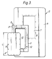
- Fig. 3 which shows the various parts from the rear, the rear side of frame sheet 2 is designated 5.
- the front side is designated 6, Fig. 1 and 2.
- the frame sheet 2 has a hole 7. This has substantially the same shape and size as the cover sheet 4, and according to a preferred embodiment the cover sheet 4 is formed of that part which is punched out of the frame sheet 2 when punching the hole 7.
- the frame sheet 2 is provided with slots 8 around the edges of the hole 7. In a corresponding way the cover disc 4 is provided with slots 9 in the edge which serve to facilitate the assembly.
- the trough shaped blister 3 has a container portion 10 and a circumferential, lateral flange 11. Between the container portion 10 and the flange 11 there is a folding 12, which initially has the shape shown in Fig. 4. More particularly, the folding 12 is located between the side wall 13 of container portion 10 and the flat flange 11. According to the embodiment the folding 12 consists of an outwardly projecting shelf or support 14 in a plane parallel with the flange 11; a web portion 15; and outwardly and inwardly projecting fold portions 16 and 17, respectively.
- the outwardly directed fold portion 16 forms a transition between the shelf 14 and the web portion 15, while the inwardly directed fold portion 17 forms a transition between the web 15 and the flange 11.
- the web portion 15 is inclined, as is shown in Fig.
- the hole folding 12 gets substantially Z- or S-shape (depending on from which side it is viewed) with a first groove 18 between the flange 11 and the exterior of the web portion 15, and a second groove 19 between the shelf 14 and the inner side of the web portion 15.
- the cover disc is as large as the hole 7.
- Fig. 4 shows the folding 12 and the adjacent parts of the frame sheet 2 and the cover disc 4 before the folding has been deformed in connection with the fixation of the joint
- Fig. 5 shows the deformed (compressed) folding 12' and adjacent parts of the frame sheet 2 and the cover disc 4 in the fixed joint.
- the cover disc 4 and the hole 7 has a length L.
- the distance between the inner side of the opposite, inwardly directed fold portions 17 has a length B1
- the distance between the outer side of the outwardly directed fold portions 16 has a length B2.
- the blister 10 can be inserted into the hole 7 through snap-in action between the outwardly projecting fold portion 16 and the edge portions of the hole 7, so that the flange 11 will rest against the rear side of the frame sheet 2, which in turn will have its edge located in the first groove 18 and that the cover disc 4 can be entered into the second groove 19 in the blister, passing the inwardly directed fold portion 17 through snap-in action between the edge portions of cover disc 11 and the inwardly directed fold portion 17 of the folding 12, so that the cover disc will rest against shelf 14, Fig. 4.
- the object to be packed is placed in the container portion 10. This object is designated 20.
- the slots 8 and 9 contribute to afford the edge portions of the hole 7 and of the cover disc 4 an improved flexibility in the described snap-in operations, which facilitates the initial mounting of the frame sheet, the blister and the cover disc to a unit.
- the flange 11 and the web portion 15 are united through an inwardly directed fold portion 15 having a rounded shape essentially without any straight transition portion, and that the web portion and the shelf are united through the outwardly projecting web portion which correspondingly has a rounded shape substantially without any straight transition portion.
- the sloping angle V1 of the web portion 15 to the plane of flange 11 is not too small. On the other hand it must not be too large in order not to jeopardize the desired development of the deformation of folding 12' in connection with the fixation of the joint. According to the preferred embodiment, the initial sloping angle V1 is 60°.
- the folding joint is made permanent/is fixed by forcing the flange 11 and the shelf 14 towards each other through a relative movement between the said parts. Possibly, heat may be supplied in order to soften the folding 12, however not to the extent that the plastic material will be sticky or will weld.
- the folding 12 is compressed, Fig. 5, so that the web portion 15' will be more horisontal, i.e. will slope with a considerably smaller angle V2 relative to the plane of the flange (the '-sign is used to indicate that the various parts in the folding have changed form and partly also changed positions).
- the outwardly projecting fold portion 16' is pressed outwards, so that the distance B2' between the outer side of the opposite, outwardly projecting fold portions 16' will be slightly larger than the original measure B2.
- the inwardly directed fold portion 17' is pressed inwards, so that the distance B1' between opposite inwardly directed fold portions will be slightly smaller than the initial measure B1.
- the angle of inclination of the web portion 15' to the plane of the flange is 15°.
- the frame sheet 2 and the cover disc 4 now are safely secured, accommodated in the web shaped grooves 18', 19'.
- the deformation of the folding thus has to the effect that the cover disc 4 can not be removed from the grip between the shelf 14 and the web portion 15' in the groove 19' without being damaged or without damaging blister material in the folding 12', and that the blister 3 can not be removed from the hole 7 in the frame sheet 2 without damaging the frame sheet or the blister material. It will in other words not be possible to deassemble and/or to empty the package without causing visible damages.
- cover disc 4 In order more safely, but still source separably, secure in the first place the cover disc 4 but also the frame sheet 2 in their sheets 18 and 19, respectively, it may be suitable to locally, e.g. in the corners, to further deform the blister in the folding 12'.
- local indentations or embossings suitably point och dash shaped embossings, can be made in the folding, so that the frame sheet and/or the cover disc is clamped firmly in the locally embossed areas. Due to the very local and restricted extension of these embossings it will, however, still be possible to separate the different parts from each other, i.e. to maintain the source separability.
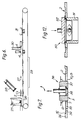
- Fig. 6 schematically illustrates how the blister package 1 can be produced from the three parts in connection with packaging the product.
- the previously manufactured frame sheets 2 are delivered from a supply store 25 to an endless conveyor belt 26 with the rear side 5 turned up.
- the belt 26 moves in the direction of arrow 27.
- the troughs 3 are dispensed from a blister store 28, are turned 120°, and are moved with the container portion 10 turned down towards that frame sheet 2 which has been placed on the conveyor belt 26 in the preceding station, so that the container portion 10 is moved through the hole 7 in sheet 2 with such a force that the shelf 14 and the upper fold portion 16 will snap-in, passing the edge of hole 7.
- the product or products 20 is or are placed in the container portion 10 in a product feeding station designated 29.
- cover disc 4 is dispensed from a supply store 30 down towards the container portion 10 in such a mode (how this can be carried out in practice will be described more in detail in the following) that the edge portion of cover disc 4 will pass the inwardly directed fold portion 17 of blister 3 to snap-in or be pressed in into the groove 19 between the web portion 15 and the shelf 14, Fig. 4. Finally the folding joint is made permanent in a compressing station 31, the finished folding joint being designated 12' in Fig. 5.
- the conveyor belt 26, Fig. 6, constitutes an endless work fixture for the frame sheets 2.
- recesses 32 are provided, having a size and a shape which correspond to those of the frame sheets 2.
- an opening 33 which represents the major part of the surface of recess 32, so that between the opening 33 and the border of recess 32 there will be formed a support shelf 34 for the frame sheet 2, Fig. 7.
- two or more such recesses 32 are provided side by side on the conveyor belt 26 in all positions for recesses along the length of the belt.
- Fig. 7 more in detail also shows a tool 36 for dispensing the troughs 3 piece by piece from the trough store 28, Fig. 6, turning the troughs 120°, and moving them with the container portion 10 turned down, towards the frame sheets 2 which have been placed in the recesses 32 in the conveyor belt 26 in the preceding station, so that each container portion 10 is moved through the hole 7 in the sheet 2 with such a force that the shelf 14 and the outwardly directed fold portion 16 will pass the edge of hole 7, said edge snapping in into the first groove 18.
- the tool 36 comprises a body 37 having such a size and shape that it will completely fill the container portion 10, when it is moved into the blister 3.
- One or more suction cups 38 are provided to hold the blister 3 by means of vacuum.
- the body 37 When the blister 3 is pressed down into the hole 7 in the frame sheet 2, the body 37 will prevent the side walls 13 of the blister to spring out, which could jeopardize the desired application of the frame sheet in the first groove 18, Fig. 4.
- the vacuum to the suction cup 38 is disconnected, and the tool 36 is lifted up and turned back 120° to the position for feeding out a new blister 3 from the supply store 28.
- Fig. 8-10 illustrate one of some conceivable methods of performing this step in the integrated process. What is difficult, basically is to bring an initial little part of the edge portion of the cover disc 4 in its place in the second groove 19 in the folding 12. As soon as this has been done, the rest of the assembly work is easier to perform.
- the blister 3 in the container portion 10 and the cover disc 4 have rounded corners. If one bends the cover disc 4, Fig. 8, so that it is somewhat shortened in the horisontal direction, the straight end portions 4a can be brought down to the shelf 14.
- the device which is used for mounting the cover disc 4 and which works according to the principals which is described in the preceding passage is generally designated 40 in Fig. 8 and 9. It consists of a bottom part or frame 41 and a top part 42.
- the frame 41 abuts the outer side of the shelf 14 (the bottom side when the bottom portion 10 is turned downwards) in the area of the opening 33 in the conveyor belt/fixture 26 and acts as a dolly.
- the upper part 42 comprises an inner female part 43, a suction cup 44 in the center of the female part 43, and a movable male part 46 between the female part 43 and an outer frame or sleeve 45 along each longitudinal side, said male part being movable in the vertical direction and having the shape of a rectangular plate which is slightly shorter than the length of the straight longitudinal edges 4b of the cover disc 4.
- the female part 43 can be moved a short distance relative to the frame 45 in the vertical direction and has a concave recess 47 in the side facing the blister 3.
- the device 40 operates in the following way. From the supply store 30, Fig. 6, a cover disc 4 is brought in under the upper part 42.
- the suction cup 44 is brought down towards the cover disc 4 by a relative movement between the suction cup 44 and the rest of the device 40 by means of motion means, not shown.
- the cover disc is sucked to the suction cup, which thereafter is returned up towards the female part 43 in the recess 47.
- the cover disc 4 obtains the bent shape which is shown in Fig. 8 and 9, so that its horisontal extension in the longitudinal direction is reduced.
- the female part 43, including the suction cup 44 and the cover disc 4 is moved down towards the blister 3, so that the straight, short edges 4a of the cover disc are pressed against the shelf 14.
- the plate shaped male parts 46 are moved downwards against the blister 3 at the same time as the vacuum of the suction cup 44 is ceased.
- the male parts 46 therefore bring the main part of the cover disc 4 downwards against the blister 3, straightening the cover disc so that the straight end portions 4a are pressed into the groove 19.
- the male parts 46 press the longitudinal edge portions 4b beyond the inwardly directed fold portion 17 in the folding 12 so that the edge portion of the cover disc 4 is snapped-in into the groove 19 around the entire circumference of the cover disc.
- the two main parts 41 and 42 of device 40 can be returned to their starting positions and the belt 26 be moved on.
- Fig. 11 illustrates an alternative technique of initiating the mounting of the cover disc 4 in the groove 19.
- the cover disc 4 is brought in obliquely so that two corners 4c and 4d enter the groove 19.
- the hole edge portion 4a is inserted into groove 19 by turning the disc 4 clockwise.
- the rest of the edge portions of the cover disc can be pressed into groove 19.
- This technique in the first place is suitable for manual application of the cover disc 4.
- the folding joint is made permanent (is fixed) in the compressing station 31 by means of device 50, Fig. 12, which comprises two tool parts 51 and 52 which, during the compression/deformation of the folding, are moved towards each other by means of motion means, not shown.
- the lower tool part 51 consists of a frame which supports shelf 14, while the upper tool part 52 consists of a plate.
- device 50 also may comprise means for heating the folding 12 in order to facilitate the deformation; however not to the extent that the plastic will be sticky or will weld.
- Fig. 13 illustrates a modification of the blister package according to the invention.
- the cover disc 4 is not completely punched out from the frame sheet 2 but only along two longsides and one shortside, so that a flap is formed, integrated with the sheet 2.
- the blister 3 is modified so far that it exhibits the said folding 12 and the flange 11 only along two longsides and along one shortside, while the opposite shortside has no such portions. This edge has been designated 12A, Fig. 13.
- the flap 4X When the package shall be assembled, the flap 4X is brought out of the way, so that the blister 3X with the container portion 10 can be brought into the opening 7X thus formed, wherein the shelf 14 of the folding snaps-in beyond the edge portion of the hole in the same way as according to the previous embodiment, and so that the edge portion 12X snaps-in beyond the brought aside flap 4X. Thereafter the flap 4X is brought back to its original position and is pressed in beyond the inwardly directed fold portion 17, Fig. 4, whereafter the folding joint is fixed through permanent deformation in those sides which include the said folding 12, in the same way as has been described above with reference i.e. to Fig. 5 and Fig. 12.
- the blister package 101 Fig. 15, according to this embodiment, is made only of two parts, namely of a blister 102 of thin, stiff, transparent plastic, and a cover disc 103, which usually consists of paper board but which as an alternative may consist of plastic.
- the blister 102 exhibits a trough shaped container portions 104, a flat portion 105, a circumferential folding 106, which in Fig. 14 is shown in its undeformed shape and a circumferential flange 107.
- the flange 107 in one end of the blister package 101 is extended - the portion 107A - and in this portion there is provided a hole 108 for hanging the package on a display stand or the like.
- the folding 106 is designed in the same mode as the folding 12 according to the first embodiment. Also the assembly operation in the relevant phases thereof corresponds to what has been described in the foregoing. The essential differences are that there is no frame sheet and that the container portion of the blister defines a substantially smaller part of the blister, while the remaining part 105 used for the exponation of a display surface on the under-lieing cover disc.
- the folding 106 is deformed in the same mode as the folding 12 according to previous embodiment, wherein the cover disc 103 is locked in in the same mode as the cover disc 4 according to previous embodiment, so that it can not be released from the grip between the shelf 114 and the deformed web portion 115' without being damaged.
- a substantial part 105 of the blister is not used as a container portion but as a protection for a portion 103A of the cover disc 103, said blister resting with its portion 105 against portion 103A.
- the surface of the cover disc portion 103A, which is facing the blister portion 105, is used as a display surface for information, sales promotion and/or decoration, and is visible through the transparent blister material.
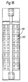
- Fig. 18 which schematically illustrates a plant for the assembly and the filling of the package according to a modified method
- a number of pallets 126 as fixtures for the frame sheets 2, said pallets having recesses 132 designed in the same mode as the recesses 32 in the conveyor belt 26 which has been described in the foregoing with reference to Fig. 6.
- each such recess 132 there is an opening, which corresponds to the major part of the surface of the recess 132, so that between the opening and the border edge of the recess 132 there is formed a support shelf for the frame sheet 2, Fig. 7.
- the pallets 126 can be moved stepwise in a line between different stations for the application of the frame sheets in the recesses 132, placing the blisters in the holes in the frame sheets, dispensing the objects which shall be packed, mounting the cover discs, and compressing the joints.
- the blister package 201 consists of three parts, namely a frame sheet 202 of paper board, a blister 203 with the shape of a trough of thin, stiff plastic material, and a cover disc 204 which also may consist of paper board.
- the cover disk 204 may consist of plastic, so that the object which is packed in the trough will be visible from all sides.
- the frame sheet has a hole with the same size and shape as the cover disc 204.
- the trough shaped blister 203 has a container portion 210 and a circumferential, lateral flange 211. Between the container portion 210 and the flange 211 there is a folding 212, which initially has the shape shown in Fig. 23. More particularly, the folding 212 is located between the sidewall 213 of container portion 210 and the flat flange 211. According to the embodiment, the folding 212 consists of a lateral shelf 214, which lies in a plane parallel with the flange 211, a web portion 215, and outwardly projected and inwardly directed fold portions 216 and 217, respectively.
- the outwardly directed fold portion 216 forms a transition between shelf 214 and web 215, while the inwardly directed fold portion 217 forms a transition between web portion 215 and flange 211.
- the web portion 215 slopes in the undeformed folding, so that the entire folding is substantially Z- or S-shaped with a first groove 218 located between the flange 211 and the outer side of web portion 215, and a second groove 219 between the shelf 214 and the inner side of web portion 215.
- the lateral flange 211 has, before the joint has been deformed for the fixation of frame sheet and cover disc, a number of ridges distributed around the circumference of the blister, so that each side of the blister has one or more such ridges.
- Each of said ridges is formed of an hollow offset, which extends upwards from the plane of flange 211.
- the ridge has a steeply sloping portion 231 in the part facing the cover disc 204, said steep portion having its base 232 adjacent to or in line with the nose of the inwardly directed fold portion 217.
- the crest is designated 233.
- the gently sloping portion is designated 235.
- the sloping angle A1 of the steep portion 231 to the plane of flange 211 is about 85°, while the gently sloping portion 235 has a sloping angle A2 of about 30°.
- the sides 236 slope inwards, so that the blisters 203 can be stacked on each other in a storage container.
- the design of the corners of the container portion is another characteristic feature of this embodiment. As is best seen in Fig. 19, the corners are designed as portions of an oblique cone 240 having its base on shelf 214, so that the cone makes point of contact with the nose of the outwardly direted fold portion 216 in the corner.
- the purpose of this design of the corners is to facilitate the application of the blister 203 in the frame sheet 202 in connection with the mounting by allowing the conically shaped corners 240 to guide the blister down into the opening of the frame sheet.
- the assembly and the fixation of the blister package 201 is performed in the following way.
- the frame sheet 202 is placed in a recess 32 in the conveyor belt 26 or in a recess 132 in a pallet 126 or in a corresponding fixture.
- the blister 203 is placed in the frame sheet 202 with the container portion 210 turned downwards, wherein the blister is guided down into the hole by means of the conically shaped corners 240, which slide against the corners in the hole in the frame sheet.
- the blister 203 is pressed down into the opening in the frame sheet so far that the flange 211 is brought into contact with the frame sheet.
- the object or objects which shall be packed is or are placed in the container portion 211.
- the cover disc 204 is placed in the container opening, the cover disc 204 being guided by the steeply sloping sides 231 of the ridges 230, Fig. 23 and Fig. 24.
- the final mounting of the cover disc 204 in groove 219 is carried out by means of a device which presses the cover disc downwards, so that the edges of the cover disc snap-in beyond the inwardly directed fold portion 217.
- the folding 211 and the ridges 230 are simultaneously deformed in one moment.
- the folding 212 is deformed in the same mode as in the previously described embodiments.
- the position of the inwardly directed folding 217 in its deformed shape has been designated 217' in Fig. 25, and the final position of the outwardly directed folding is designated 217'.
- the ridges 230 are flattened at the same time as they are being folded in over the cover disc 204.
- An inwardly directed, tongue-shaped fold portion formed of such a deformed ridge 230 is designated 250 in Fig. 25.
- the blister 303 in the undeformed shape has a lateral flange 211 as above and a shelf 314 which is broader than the shelf according to the previous embodiments.
- the folding 312 in this case is reduced to define a short, inwardly sloping portion 315 between flange 11 and shelf 314, Fig. 26.
- the flange 311 is provided with one or more ridges 330 along one or more of the sides of the blister, as according to previous embodiment, and the shelf 314 is provided with correspondingly designed cavities in shelf 314. They may, as according to the shown embodiment, be located opposite the ridges 330, but they may also be displaced sidewize in relation to ridges 330.
- the joint in this case is fixed through compression, wherein the ridges 330 are folded in on top of the cover disc 304, while the depressions or cavities 340 are folded outwards beneath the frame sheet 302, so that the cover disc is secured between inwardly directed, tongue-shaped portions 350 and the shelf 314, while the frame sheet 302 is secured between outwardly directed, tongue-shaped portions 360 and the flange 311.
Landscapes
- Engineering & Computer Science (AREA)
- Mechanical Engineering (AREA)
- Chemical & Material Sciences (AREA)
- Composite Materials (AREA)
- Packages (AREA)
Abstract
Description
- The present invention relates to a blister package comprising a blister in the form of a trough or the like of a thin, stiff plastic material, said blister including a container portion, a flange extending as a brim around at least the major part of the circumference of the blister, a shelf between the container portion and the flange, and a cover disc contacting the shelf, providing a closure of the container portion, said cover disc being detachably fastened between on one side said shelf and on the other side, in the region of at least some of the sides of the blister, at least one inwardly directed fold portion projecting in over the cover disc.
- The invention also relates to a method of manufacturing a blister package comprising a blister in the form of a trough or the like of thin, stiff plastic material, including a container portion, a flange extending as a brim around at least the major part of the circumference of the blister, a shelf between the container portion and the flange, and a cover disc contacting the shelf, providing a closure of the container portion, said cover disc initially being brought to contact with said shelf or support. The use of the expressions blister and trough shall not restrict the scope of the invention or the patent, which expressions may comprise all more or less blister shaped caps, boxes, bowls, blisters etc, which in the packaging art are referred to as blisters, regardless their shapes and sizes.
- Conventionally a blister package consists of a blister in the form of a trough or the like, which with a circumferential flange is secured to a board sheet through heat sealing. The board sheet for this purpose is coated with a layer of lacquer containing a plastic material of the type which allows the blister to be secured to the board through welding. Normally, the blister consists of PVC although also polyester blisters are known. The board sheet is used for several purposes. It shall provide a display surface for decoration, sales promotion and information, and also for increasing the total size of the package in order to render pilfering more difficult in those cases the trough with the container member has comparatively small dimensions. The board sheet in some embodiments also may serve as a closure for the blister, the cover sheet in these cases being a part of the board sheet.
- In an increasing number of countries demands are raised on preseparation of domestic wastes at source. These demands are due to environmental-technical as well as economic reasons. It is important in both these cases that the sorted plastic material does not contain any paper rests, since this considerably would reduce the possibilities of re-using the plastic material. It is correspondingly desirable that the sorted paper material as far as possible does not contain any plastic material. Therefore it is necessary or at least desirable, as far as blister packages are concerned, that the torn off blisters are not contaminated with fragments from the board sheet. This, however, is the case when it is the matter of conventional blister packages, as fragments of the board sheet, which is secured on the blister, are torn off and will stay on the blister, when the blister and the board sheet are separated.
- In order to avoid the above mentioned problems, many blister packages have been developed in the past, which allow assorting at the source. Thus there are blister packages which entirely consist of plastic; blister packages where the blister is secured to the sheet by means of lock-in closures; blister packages with double-folded blisters; blister packages having the blister secured by means of clips or by means of sliding members, etc, just to mention a few. None of these or other systems which are now available, however, are ideal. Among new problems involved in the new systems may be mentioned that the packings often are more expensive; that they do not guarantee nonauthorized access to the content in the package; that they restrict the possibilities of designing the package; that new re-use problems are introduced (clips); that the manufacturing is more difficult; etc.
- US-A-2 931 493 discloses a blister package of the type defined in the preamble of claim 1. The inwardly directed fold portion is comparatively short and has sharp corners and a vertical end wall, which does not promote a safe attachement of the cover disc.
- It is the purpose of the invention to provide an improved blister package which shall have the following features:
- the board and the plastic members shall be so firmly united with each other that they can not get loose from each other by accident, and nor shall it be possible to manipulate them to get access to the content without causing visible damage, at the same time as the package shall be possible to source separate;
- the blister material shall be able to be chosen among any conceivable plastic material, including plastic materials which are favourable from an environmental point of view;
- the cover disc as well as any possible frame sheet shall be able to be chosen among any material, including board or plastic which can be re-utilized;
- the fastening of the blister to the cover disc and as the case may be, to the frame sheet shall not require that the cover disc and/or the frame sheet are lacquered;
- any welding or glueing shall not be required;
- the packaging and the manufacturing of the package shall be able to be carried out by simple and nonexpensive machine equipment;
- it shall be able to give the package an attractive appearance;
- it shall be able to use the rear side of the sealing disc and possibly also an essential part of its front side and also the front and rear sides of any frame sheet, as a display surface for information, sales promotion, and decoration purposes.
- It is also an object of the invention to provide a method for the assembley of the various parts to obtain a package having the said features.
- The above mentioned objects and advantages can be achieved with a package which according to the invention is characterized therein that the inwardly directed fold portion has the shape of a tongue with a rounded tip. (It is presupposed here and in the appending claims when using prepositions like over, under, up, and down, that the package has its cover disc facing upwards and its container portion facing downwards.)
- According to one aspect of the invention, the inwardly directed tongue-shaped fold portion is an integrated part of a folding which, starting from the flange, includes said tongue-shaped, inwardly directed fold portion, a web portion, a tongue-shaped, outwardly directed fold portion, and said shelf or support portion which extends inwards from the outwardly directed fold portion, so that a first groove is formed outside of the inwardly directed fold portion, which first groove extends around at least the major part of the circumference of the trough, and that a second groove is formed inside of the outwardly directed fold portion, said second groove also extending around at least the major part of the trough, said cover disc being secured in said second groove.
- According to another aspect of the invention, the package also comprises a frame sheet having a punched hole, the blister being releasably fastened to the frame sheet therein that the edge portion of the punched hole is secured between on one side said flange and on the other side, in the region of at least some of the sides of the blister, at least one tongue-shaped, outwardly directed fold portion which, formed through permanent deformation of blister material, projects outwards beneath the frame sheet. This tongue-shaped, outwardly directed fold portion entirely or partly may be formed from at least one depression, which in the undeformed state forms a hollow cavity in said shelf, which depression through said deformation is folded out beneath the frame or is formed of a deformed part of the folding or of combinations of these two alternatives.
- The method of mounting the blister package in the first place is characterised in that the cover disc is brought to contact with said shelf or support, and that in a subsequent moment, in the area of at least some of the sides of the blister, at least one tongue-shaped, inwardly directed fold portion having a rounded tip is caused to project in over the cover disc through permanent deformation of blister material, so that the cover disc detachably is fixed between the shelf and said tongue-shaped, inwardly directed fold portion having a rounded tip. If also a frame sheet is included in the package assembly, the blister suitably is mounted in the frame sheet prior to mounting the cover disc. The permanent deformation, securing the cover disc and the frame sheet, suitably is performed in a subsequent third step.
- According to a development of the invention, concerning a blister package having a folding comprising a web portion, as above described, the web portion initially slopes from said flange obliquely downwards-outwards under a certain sloping angle against the plane of the flange. That or those objects which shall be packed is/are placed in the container portion, the folding having said initial shape. Thereafter, the cover disc is moved beyond the inwardly projecting fold portion, prior to its deformation, until the cover disc abuts said shelf in the area of said second groove. The shelf and the flange thereafter, in a subsequent moment are pressed towards each other under permanent deformation of the folding, so that the sloping angle of the web portion relative to the plane of the flange is reduced, the inwardly fold portion being pressed inwards, the outwardly projecting fold portion being pressed outwards, and said first and said second groove deepening, so that the cover disc is secured stronger but still separatably in said second groove between the web portion and the shelf.
- As far as the sloping angle of the web portion prior and after the deformation operation is concerned, one can generally say that the initial angle between the plane of the flange and the web portion shall be so much less than 90° that the angle creates a reliable trigger of the of the desired development of the deformation, as the flange and the ridge are pressed towards each other. At the same time, the sloping angle must not be so small that the mounting of the cover disc and the frame sheet, respectively, is jeopardized. These conditions imply that the sloping angle of the web portion against the plane of the flange initially should be at least 45° and not more than 80°, preferably 50-70°, suitably about 60°. This sloping angle is drastically reduced by the compression of the folding, so that it after the deformation operation is less than half the initial sloping angle. A suitale sloping angle of the finished container should be between 10 and 20°.
- It is a characteristic feature of the package that at least the outwardly projecting fold portion in section has a rounded shape substantially without any straight transition portion between said ridge and said web portion. The outwardly projecting fold portion and adjacent parts of ridge and web portion in section thus has the shape of a wedge with a rounded tip. The rounded shape, which the fold portions have also intially, although to some less degree, contribute to facilitating the initial mounting of the cover disc and the frame sheet, respectively, and to guarantee a desired result of the deformation operation. At the same time the rounded shape of the fold portions offer good oportunities of fixing the cover disc and the frame sheet, respectively, in their positions in their respective grooves, but at the same time maintaining the possibility of separating the different parts from each other in order to make the desired source separtion possible.
- According to a most preferred embodiment, the blister is provided with ridges, which are deformed to form inwardly directed tongue-shaped fold portion, wherein it is suitable that the steep front of the ridge slopes against the plane of the flange at a sloping angle somewhat less than 90°, suitably 80-88°, preferably about 85°. The ridges in this case can work as guides for the cover disc, when mounting the cover disc, which substantially facilitates the assembly work by the fact that the cover disc, being guided against the steep portions of the ridges, can be pressed down by a simple feading movement to contact said shelf, even if the ridges are provided in combination with the S- or Z-shaped folding, which also is intended to be deformed in order to provide a permanent but still detachable fixation of the cover disc, and of the frame sheet in the case also a frame sheet is mounted, and wherein the cover disc shall snap-in in said second groove in the folding.
- Further features and aspects of the invention will be apparent from the appending claims ad from the following description of some embodiments of the blister package and of the method of assembling the package, i.e. mounting the various parts of the package.
- In the following description reference will be made to the accompanying drawings, in which
- Fig. 1
- shows a blister package according to a first preferred embodiment of the invention, illustration a phase of the manufacturing prior to final fixation of the parts of the package;
- Fig. 2
- is a longitudinal section through the finished blister package according to the first preferred embodiment;
- Fig. 3
- shows from the rear the three parts which shall form the blister package;
- Fig. 4
- shows the initial shape of the folding and the positions of the cover disc and the frame sheet prior to fixation;
- Fig. 5
- shows the shape of the folding and the positions of the frame sheet and the cover disc in the finished folding joint;
- Fig. 6
- schematically shows the manufacturing of the blister packaging according to a conceivable method;
- Fig. 7
- by way of example shows how the blister can be mounted in a frame sheet;
- Fig. 8 and 9
- by way of example illustrate how the cover disc can be mounted in the blister;
- Fig. 10
- shows the initial phase of the mounting of the cover disc in the blister according to the example illustrated in Fig. 8 and 9, however not with any frame sheet;
- Fig. 10A
- is a view along the line XA-XA in Fig. 10;
- Fig. 10B
- is a view along the line XB-XB in Fig. 10;
- Fig. 11
- illustrates another example of mounting the cover disc in the blister; particularly suited for manual operation;
- Fig. 12
- shows how the various parts can be fixed relative to each other;
- Fig. 13
- is a longitudinal section through a blister package according to a second embodiment of the invention;
- Fig. 14
- shows a blister package according to a third embodiment of the invention, illustrating a phase of the manufacturing prior to final fixation of the parts of the package;
- Fig. 15
- is a longitudinal section through the finished blister package according to said third embodiment;
- Fig. 16 and 17
- show the positions of the folding and of the cover disc prior to and after the fixation of the cover disc through deformation of the folding according to said third embodiment (the part showed in a circle in Fig. 15);
- Fig. 18
- schematically illustrates a plant for mounting and filling the package according to a modified method;
- Fig. 19
- is a perspective view of still another preferred embodiment of the package according to the invention;
- Fig. 20
- is a side view of the package shown in Fig. 19;
- Fig. 21
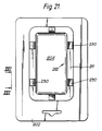
- shows the same package in a view along the line XXI-XXI in Fig. 20;
- Fig. 22
- is a view along the line XXII-XXII in Fig 21;
- Fig. 23
- shows a section along the line XXIII-XXIII in Fig. 22;
- Fig. 24
- is a section along the line XXIV-XXIV in Fig. 22;
- Fig. 25
- shows the same detail as Fig. 24 but after fixation of the joint;
- Fig. 26
- is a section through a detail corresponding to the detail according to Fig. 24 but according to still another conceivable embodiment; and
- Fig. 27
- shows the detail of Fig. 26 after deformation.
- The blister package 1, Fig. 2, according to the preferred embodiment is made of three parts, namely a
frame sheet 2 of paper board, a blister having the shape of atrough 3 of thin, stiff plastic and acover disc 4, which also may consist of paper board. As an alternative the cover sheet may consist of plastic, so that the object which is packaged in the container portion will be visible from all sides. In Fig. 3, which shows the various parts from the rear, the rear side offrame sheet 2 is designated 5. The front side is designated 6, Fig. 1 and 2. Theframe sheet 2 has ahole 7. This has substantially the same shape and size as thecover sheet 4, and according to a preferred embodiment thecover sheet 4 is formed of that part which is punched out of theframe sheet 2 when punching thehole 7. Theframe sheet 2 is provided with slots 8 around the edges of thehole 7. In a corresponding way thecover disc 4 is provided with slots 9 in the edge which serve to facilitate the assembly. - The trough shaped
blister 3 has acontainer portion 10 and a circumferential,lateral flange 11. Between thecontainer portion 10 and theflange 11 there is afolding 12, which initially has the shape shown in Fig. 4. More particularly, thefolding 12 is located between theside wall 13 ofcontainer portion 10 and theflat flange 11. According to the embodiment thefolding 12 consists of an outwardly projecting shelf orsupport 14 in a plane parallel with theflange 11; aweb portion 15; and outwardly and inwardly projectingfold portions fold portion 16 forms a transition between theshelf 14 and theweb portion 15, while the inwardly directedfold portion 17 forms a transition between theweb 15 and theflange 11. Theweb portion 15 is inclined, as is shown in Fig. 4, so that the hole folding 12 gets substantially Z- or S-shape (depending on from which side it is viewed) with afirst groove 18 between theflange 11 and the exterior of theweb portion 15, and asecond groove 19 between theshelf 14 and the inner side of theweb portion 15. According to the embodiment the cover disc is as large as thehole 7. - Fig. 4 shows the
folding 12 and the adjacent parts of theframe sheet 2 and thecover disc 4 before the folding has been deformed in connection with the fixation of the joint, while Fig. 5 shows the deformed (compressed) folding 12' and adjacent parts of theframe sheet 2 and thecover disc 4 in the fixed joint. Thecover disc 4 and thehole 7 has a length L. In theundeformed folding 12, Fig. 4, the distance between the inner side of the opposite, inwardly directedfold portions 17 has a length B1, and the distance between the outer side of the outwardly directedfold portions 16 has a length B2. For these lengths the following expression applies: B1 < L <B2. This in turn means that theblister 10 can be inserted into thehole 7 through snap-in action between the outwardly projectingfold portion 16 and the edge portions of thehole 7, so that theflange 11 will rest against the rear side of theframe sheet 2, which in turn will have its edge located in thefirst groove 18 and that thecover disc 4 can be entered into thesecond groove 19 in the blister, passing the inwardly directedfold portion 17 through snap-in action between the edge portions ofcover disc 11 and the inwardly directedfold portion 17 of thefolding 12, so that the cover disc will rest againstshelf 14, Fig. 4. Before thecover disc 4 is mounted as above described, the object to be packed is placed in thecontainer portion 10. This object is designated 20. - When using
frame sheets 2 and coverdiscs 4 having the shape shown in Fig. 3, the slots 8 and 9 contribute to afford the edge portions of thehole 7 and of thecover disc 4 an improved flexibility in the described snap-in operations, which facilitates the initial mounting of the frame sheet, the blister and the cover disc to a unit. However, it is possible to perform this initial mounting with suitable method and means, even if the frame sheet and the cover disc are void of slots 8 and 9. It is herein of importance that theflange 11 and theweb portion 15 are united through an inwardly directedfold portion 15 having a rounded shape essentially without any straight transition portion, and that the web portion and the shelf are united through the outwardly projecting web portion which correspondingly has a rounded shape substantially without any straight transition portion. It is also important that the sloping angle V1 of theweb portion 15 to the plane offlange 11 is not too small. On the other hand it must not be too large in order not to jeopardize the desired development of the deformation of folding 12' in connection with the fixation of the joint. According to the preferred embodiment, the initial sloping angle V1 is 60°. - The folding joint is made permanent/is fixed by forcing the
flange 11 and theshelf 14 towards each other through a relative movement between the said parts. Possibly, heat may be supplied in order to soften thefolding 12, however not to the extent that the plastic material will be sticky or will weld. Through the said relative movement, thefolding 12 is compressed, Fig. 5, so that the web portion 15' will be more horisontal, i.e. will slope with a considerably smaller angle V2 relative to the plane of the flange (the '-sign is used to indicate that the various parts in the folding have changed form and partly also changed positions). At the same time the outwardly projecting fold portion 16' is pressed outwards, so that the distance B2' between the outer side of the opposite, outwardly projecting fold portions 16' will be slightly larger than the original measure B2. In a corresponding way the inwardly directed fold portion 17' is pressed inwards, so that the distance B1' between opposite inwardly directed fold portions will be slightly smaller than the initial measure B1. According to the embodiment, the angle of inclination of the web portion 15' to the plane of the flange is 15°. Through the deformation the two grooves 18' and 19' will adopt, in cross section, the pronounced shape of a wedge having a rounded tip. Theframe sheet 2 and thecover disc 4 now are safely secured, accommodated in the web shaped grooves 18', 19'. The deformation of the folding thus has to the effect that thecover disc 4 can not be removed from the grip between theshelf 14 and the web portion 15' in the groove 19' without being damaged or without damaging blister material in the folding 12', and that theblister 3 can not be removed from thehole 7 in theframe sheet 2 without damaging the frame sheet or the blister material. It will in other words not be possible to deassemble and/or to empty the package without causing visible damages. On the other hand it is possible, in connection with breaking the blister package, to separate the three parts - theframe sheet 2, theblister 3, and the cover sheet 4 - from each other without any rests of theframe sheet 2 or of thecover disc 4 remaining on theblister 3 and vice versa. The package in other words is possible to source separate. - In order more safely, but still source separably, secure in the first place the
cover disc 4 but also theframe sheet 2 in theirsheets - Fig. 6 schematically illustrates how the blister package 1 can be produced from the three parts in connection with packaging the product. The previously manufactured
frame sheets 2 are delivered from asupply store 25 to anendless conveyor belt 26 with therear side 5 turned up. Thebelt 26 moves in the direction ofarrow 27. Thetroughs 3 are dispensed from ablister store 28, are turned 120°, and are moved with thecontainer portion 10 turned down towards thatframe sheet 2 which has been placed on theconveyor belt 26 in the preceding station, so that thecontainer portion 10 is moved through thehole 7 insheet 2 with such a force that theshelf 14 and theupper fold portion 16 will snap-in, passing the edge ofhole 7. Thereafter the product orproducts 20 is or are placed in thecontainer portion 10 in a product feeding station designated 29. In the next station, thecover disc 4 is dispensed from asupply store 30 down towards thecontainer portion 10 in such a mode (how this can be carried out in practice will be described more in detail in the following) that the edge portion ofcover disc 4 will pass the inwardly directedfold portion 17 ofblister 3 to snap-in or be pressed in into thegroove 19 between theweb portion 15 and theshelf 14, Fig. 4. Finally the folding joint is made permanent in a compressingstation 31, the finished folding joint being designated 12' in Fig. 5. - The
conveyor belt 26, Fig. 6, constitutes an endless work fixture for theframe sheets 2. In the outer side of the conveyor belt/fixture 26recesses 32 are provided, having a size and a shape which correspond to those of theframe sheets 2. In eachsuch recess 32 is anopening 33, which represents the major part of the surface ofrecess 32, so that between theopening 33 and the border ofrecess 32 there will be formed asupport shelf 34 for theframe sheet 2, Fig. 7. Suitably two or moresuch recesses 32 are provided side by side on theconveyor belt 26 in all positions for recesses along the length of the belt. - Fig. 7 more in detail also shows a
tool 36 for dispensing thetroughs 3 piece by piece from thetrough store 28, Fig. 6, turning the troughs 120°, and moving them with thecontainer portion 10 turned down, towards theframe sheets 2 which have been placed in therecesses 32 in theconveyor belt 26 in the preceding station, so that eachcontainer portion 10 is moved through thehole 7 in thesheet 2 with such a force that theshelf 14 and the outwardly directedfold portion 16 will pass the edge ofhole 7, said edge snapping in into thefirst groove 18. Thetool 36 comprises a body 37 having such a size and shape that it will completely fill thecontainer portion 10, when it is moved into theblister 3. One ormore suction cups 38 are provided to hold theblister 3 by means of vacuum. When theblister 3 is pressed down into thehole 7 in theframe sheet 2, the body 37 will prevent theside walls 13 of the blister to spring out, which could jeopardize the desired application of the frame sheet in thefirst groove 18, Fig. 4. When theblister 3 thus has been brought to its place and the frame sheet has snapped-in in thefirst groove 18 to rest against theflange 11, the vacuum to thesuction cup 38 is disconnected, and thetool 36 is lifted up and turned back 120° to the position for feeding out anew blister 3 from thesupply store 28. - The application of the
cover disc 4 is a critical moment. Fig. 8-10 illustrate one of some conceivable methods of performing this step in the integrated process. What is difficult, basically is to bring an initial little part of the edge portion of thecover disc 4 in its place in thesecond groove 19 in thefolding 12. As soon as this has been done, the rest of the assembly work is easier to perform. According to the embodiment ofblister 3 and coverdisc 4 which is shown in Fig. 10, theblister 3 in thecontainer portion 10 and thecover disc 4 have rounded corners. If one bends thecover disc 4, Fig. 8, so that it is somewhat shortened in the horisontal direction, the straight end portions 4a can be brought down to theshelf 14. When the cover disc thereafter is straightened, the said end portions 4a are pressed into thegroove 19 beneath the inwardly directedfold portion 17. In the same moment, or immediately thereafter, the longitudinal edges 4b are forced into thegroove 19 with snap-in action relative to the inwardly directedfold portion 17. - The device which is used for mounting the
cover disc 4 and which works according to the principals which is described in the preceding passage is generally designated 40 in Fig. 8 and 9. It consists of a bottom part orframe 41 and atop part 42. Theframe 41 abuts the outer side of the shelf 14 (the bottom side when thebottom portion 10 is turned downwards) in the area of theopening 33 in the conveyor belt/fixture 26 and acts as a dolly. Theupper part 42 comprises an innerfemale part 43, asuction cup 44 in the center of thefemale part 43, and a movablemale part 46 between thefemale part 43 and an outer frame orsleeve 45 along each longitudinal side, said male part being movable in the vertical direction and having the shape of a rectangular plate which is slightly shorter than the length of the straight longitudinal edges 4b of thecover disc 4. Thefemale part 43 can be moved a short distance relative to theframe 45 in the vertical direction and has aconcave recess 47 in the side facing theblister 3. - The
device 40 operates in the following way. From thesupply store 30, Fig. 6, acover disc 4 is brought in under theupper part 42. Thesuction cup 44 is brought down towards thecover disc 4 by a relative movement between thesuction cup 44 and the rest of thedevice 40 by means of motion means, not shown. By means of vacuum, the cover disc is sucked to the suction cup, which thereafter is returned up towards thefemale part 43 in therecess 47. As a result, thecover disc 4 obtains the bent shape which is shown in Fig. 8 and 9, so that its horisontal extension in the longitudinal direction is reduced. Thereafter thefemale part 43, including thesuction cup 44 and thecover disc 4, is moved down towards theblister 3, so that the straight, short edges 4a of the cover disc are pressed against theshelf 14. Thereafter the plate shapedmale parts 46 are moved downwards against theblister 3 at the same time as the vacuum of thesuction cup 44 is ceased. Themale parts 46 therefore bring the main part of thecover disc 4 downwards against theblister 3, straightening the cover disc so that the straight end portions 4a are pressed into thegroove 19. Finally, themale parts 46 press the longitudinal edge portions 4b beyond the inwardly directedfold portion 17 in thefolding 12 so that the edge portion of thecover disc 4 is snapped-in into thegroove 19 around the entire circumference of the cover disc. Thereafter the twomain parts device 40 can be returned to their starting positions and thebelt 26 be moved on. - Fig. 11 illustrates an alternative technique of initiating the mounting of the
cover disc 4 in thegroove 19. According to this alternative method, thecover disc 4 is brought in obliquely so that two corners 4c and 4d enter thegroove 19. Thereafter the hole edge portion 4a is inserted intogroove 19 by turning thedisc 4 clockwise. When this has been done, the rest of the edge portions of the cover disc can be pressed intogroove 19. This technique in the first place is suitable for manual application of thecover disc 4. - Finally, the folding joint is made permanent (is fixed) in the compressing
station 31 by means ofdevice 50, Fig. 12, which comprises twotool parts lower tool part 51 consists of a frame which supportsshelf 14, while theupper tool part 52 consists of a plate. Possibly,device 50 also may comprise means for heating thefolding 12 in order to facilitate the deformation; however not to the extent that the plastic will be sticky or will weld. - Fig. 13 illustrates a modification of the blister package according to the invention. In this case, the
cover disc 4 is not completely punched out from theframe sheet 2 but only along two longsides and one shortside, so that a flap is formed, integrated with thesheet 2. Further theblister 3 is modified so far that it exhibits the saidfolding 12 and theflange 11 only along two longsides and along one shortside, while the opposite shortside has no such portions. This edge has been designated 12A, Fig. 13. When the package shall be assembled, theflap 4X is brought out of the way, so that theblister 3X with thecontainer portion 10 can be brought into the opening 7X thus formed, wherein theshelf 14 of the folding snaps-in beyond the edge portion of the hole in the same way as according to the previous embodiment, and so that the edge portion 12X snaps-in beyond the brought asideflap 4X. Thereafter theflap 4X is brought back to its original position and is pressed in beyond the inwardly directedfold portion 17, Fig. 4, whereafter the folding joint is fixed through permanent deformation in those sides which include the saidfolding 12, in the same way as has been described above with reference i.e. to Fig. 5 and Fig. 12. - In the embodiment according to Fig. 14-17, no frame sheet is provided. The
blister package 101, Fig. 15, according to this embodiment, is made only of two parts, namely of ablister 102 of thin, stiff, transparent plastic, and acover disc 103, which usually consists of paper board but which as an alternative may consist of plastic. - The
blister 102 exhibits a trough shapedcontainer portions 104, aflat portion 105, acircumferential folding 106, which in Fig. 14 is shown in its undeformed shape and acircumferential flange 107. Theflange 107 in one end of theblister package 101 is extended - theportion 107A - and in this portion there is provided ahole 108 for hanging the package on a display stand or the like. - The
folding 106 is designed in the same mode as the folding 12 according to the first embodiment. Also the assembly operation in the relevant phases thereof corresponds to what has been described in the foregoing. The essential differences are that there is no frame sheet and that the container portion of the blister defines a substantially smaller part of the blister, while the remainingpart 105 used for the exponation of a display surface on the under-lieing cover disc. At the fixation of the joint, thefolding 106 is deformed in the same mode as the folding 12 according to previous embodiment, wherein thecover disc 103 is locked in in the same mode as thecover disc 4 according to previous embodiment, so that it can not be released from the grip between the shelf 114 and the deformed web portion 115' without being damaged. On the other hand it is possible, in connection with breaking the blister package, to separate theblister 102 and thecover disc 103 from each other without any rests of thecover disc 103 being remained on theblister 102 and vice versa. The package in other words will be source separatable. In the finished package, Fig. 15, asubstantial part 105 of the blister is not used as a container portion but as a protection for aportion 103A of thecover disc 103, said blister resting with itsportion 105 againstportion 103A. The surface of thecover disc portion 103A, which is facing theblister portion 105, is used as a display surface for information, sales promotion and/or decoration, and is visible through the transparent blister material. - According to Fig. 18, which schematically illustrates a plant for the assembly and the filling of the package according to a modified method, there are used a number of
pallets 126 as fixtures for theframe sheets 2, saidpallets having recesses 132 designed in the same mode as therecesses 32 in theconveyor belt 26 which has been described in the foregoing with reference to Fig. 6. Thus in eachsuch recess 132 there is an opening, which corresponds to the major part of the surface of therecess 132, so that between the opening and the border edge of therecess 132 there is formed a support shelf for theframe sheet 2, Fig. 7. Thepallets 126 can be moved stepwise in a line between different stations for the application of the frame sheets in therecesses 132, placing the blisters in the holes in the frame sheets, dispensing the objects which shall be packed, mounting the cover discs, and compressing the joints. - In the embodiment according to Fig. 19-25, the
blister package 201 consists of three parts, namely aframe sheet 202 of paper board, ablister 203 with the shape of a trough of thin, stiff plastic material, and acover disc 204 which also may consist of paper board. As an alternative, thecover disk 204 may consist of plastic, so that the object which is packed in the trough will be visible from all sides. As in accordance with the embodiments described in the foregoing the frame sheet has a hole with the same size and shape as thecover disc 204. - The trough shaped
blister 203 has acontainer portion 210 and a circumferential,lateral flange 211. Between thecontainer portion 210 and theflange 211 there is afolding 212, which initially has the shape shown in Fig. 23. More particularly, thefolding 212 is located between thesidewall 213 ofcontainer portion 210 and theflat flange 211. According to the embodiment, thefolding 212 consists of alateral shelf 214, which lies in a plane parallel with theflange 211, aweb portion 215, and outwardly projected and inwardly directedfold portions fold portion 216 forms a transition betweenshelf 214 andweb 215, while the inwardly directedfold portion 217 forms a transition betweenweb portion 215 andflange 211. Theweb portion 215 slopes in the undeformed folding, so that the entire folding is substantially Z- or S-shaped with afirst groove 218 located between theflange 211 and the outer side ofweb portion 215, and asecond groove 219 between theshelf 214 and the inner side ofweb portion 215. - The above features of the embodiment are in common with those of Fig. 1-5. According to the embodiment of Fig. 19-25, the
lateral flange 211 has, before the joint has been deformed for the fixation of frame sheet and cover disc, a number of ridges distributed around the circumference of the blister, so that each side of the blister has one or more such ridges. Each of said ridges is formed of an hollow offset, which extends upwards from the plane offlange 211. The ridge has a steeply slopingportion 231 in the part facing thecover disc 204, said steep portion having itsbase 232 adjacent to or in line with the nose of the inwardly directedfold portion 217. The crest is designated 233. From thecrest 233 the ridge slopes at a smaller sloping angle A2 in the direction towards theedge 234 offlange 211. The gently sloping portion is designated 235. The sloping angle A1 of thesteep portion 231 to the plane offlange 211 is about 85°, while the gently sloping portion 235 has a sloping angle A2 of about 30°. Also thesides 236 slope inwards, so that theblisters 203 can be stacked on each other in a storage container. - The design of the corners of the container portion is another characteristic feature of this embodiment. As is best seen in Fig. 19, the corners are designed as portions of an
oblique cone 240 having its base onshelf 214, so that the cone makes point of contact with the nose of the outwardlydireted fold portion 216 in the corner. The purpose of this design of the corners is to facilitate the application of theblister 203 in theframe sheet 202 in connection with the mounting by allowing the conically shapedcorners 240 to guide the blister down into the opening of the frame sheet. - The assembly and the fixation of the
blister package 201 is performed in the following way. Theframe sheet 202 is placed in arecess 32 in theconveyor belt 26 or in arecess 132 in apallet 126 or in a corresponding fixture. Thereafter theblister 203 is placed in theframe sheet 202 with thecontainer portion 210 turned downwards, wherein the blister is guided down into the hole by means of the conically shapedcorners 240, which slide against the corners in the hole in the frame sheet. Theblister 203 is pressed down into the opening in the frame sheet so far that theflange 211 is brought into contact with the frame sheet. Thereafter the object or objects which shall be packed is or are placed in thecontainer portion 211. In the next station, thecover disc 204 is placed in the container opening, thecover disc 204 being guided by the steeply slopingsides 231 of theridges 230, Fig. 23 and Fig. 24. The final mounting of thecover disc 204 ingroove 219 is carried out by means of a device which presses the cover disc downwards, so that the edges of the cover disc snap-in beyond the inwardly directedfold portion 217. - Finally, the
folding 211 and theridges 230 are simultaneously deformed in one moment. Thefolding 212 is deformed in the same mode as in the previously described embodiments. The position of the inwardly directed folding 217 in its deformed shape has been designated 217' in Fig. 25, and the final position of the outwardly directed folding is designated 217'. Theridges 230 are flattened at the same time as they are being folded in over thecover disc 204. An inwardly directed, tongue-shaped fold portion formed of such adeformed ridge 230 is designated 250 in Fig. 25. Those inwardly directed, tongue-shaped fold portions 217' which are formed of thefold portions 217, which are part of thefolding 212 thus will alternate with extended tongue-shapedfold portions 250 around the circumference of the joint, which further strengthens the fixation of thecover disc 204 in groove 219'. This very efficiently prevents thecover disc 204 from being removed by accident or being removed without visible damage. - In the embodiment according to Fig. 26 and Fig. 27, the
blister 303 in the undeformed shape has alateral flange 211 as above and ashelf 314 which is broader than the shelf according to the previous embodiments. The folding 312 in this case is reduced to define a short, inwardly slopingportion 315 betweenflange 11 andshelf 314, Fig. 26. Theflange 311 is provided with one ormore ridges 330 along one or more of the sides of the blister, as according to previous embodiment, and theshelf 314 is provided with correspondingly designed cavities inshelf 314. They may, as according to the shown embodiment, be located opposite theridges 330, but they may also be displaced sidewize in relation toridges 330. The joint in this case is fixed through compression, wherein theridges 330 are folded in on top of thecover disc 304, while the depressions orcavities 340 are folded outwards beneath theframe sheet 302, so that the cover disc is secured between inwardly directed, tongue-shapedportions 350 and theshelf 314, while theframe sheet 302 is secured between outwardly directed, tongue-shapedportions 360 and theflange 311.
Claims (13)
- Blister package comprising a blister (3, 102, 203) in the form of a trough or the like of a thin, stiff plastic material, said blister including a container portion (10, 104, 210), a flange (11, 107, 211) extending as a brim around at least the major part of the circumference of the blister, a shelf (14, 105, 214) between the container portion and the flange, and a cover disc (4, 103, 204) contacting the shelf, providing a closure of the container portion, said cover disc being detachably fastened between on one side said shelf and on the other side, in the region of at least some of the sides of the blister, at least one inwardly directed fold portion (17', 217', 250) projecting in over the cover disc, characterized in that the inwardly directed fold portion has the shape of a tongue with a rounded tip.
- Blister package according to claim 1, characterized in that the inwardly directed, tongue-shaped fold portion in cross section has the substantial shape of a wedge with a rounded tip.
- Blister package according to claim 1 or 2, characterized in that the inwardly directed tongue-shaped fold portion (17', 217') is an integrated part of a folding (12' 212') which, starting from the flange (11, 211), includes said tongue-shaped, inwardly directed fold portion, a web portion (15, 215'), a tongue-shaped, outwardly directed fold portion (16', 216'), and said shelf or support portion (14, 214) which extends inwards from the outwardly directed fold portion, so that a first groove (18', 218') is formed outside of the inwardly directed fold portion, said first groove extending around at least a major part of the circumference of a trough, and that a second groove (19', 219') is formed inside of the outwardly directed fold portion, said second groove also extending around at least the major part of the trough, said cover disc (4, 204) being secured in said second groove.
- Blister package according to any of claims 1-3, characterized in that the package also comprises a frame sheet (2, 202) having a punched hole, the blister being detachably fastened to the frame sheet therein that the edge portion of the punched hole is secured between on one side said flange (11, 211) and on the other side, in a region of at least some of the sides of blister, at least a tongue-shaped, outwardly directed fold portion (16', 216') which projects outwards beneath the frame sheet.
- Blister package according to claim 4, characterized in that the edge portion of the frame sheet is recessed (inserted) in said first groove (18', 218') in the region of said hole.
- Blister package according to any of claims 3-5, characterized in that the sloping angle (V2) of the web portion against the plane of the flange is between 10 and 20°.
- Blister package according to any of claims 1-6, characterized in that said at least one inwardly directed, tongue-shaped fold portion (217') alternates with more extended, inwardly directed tongue-shaped fold portions (250).
- Method of manufacturing a blister package comprising a blister (2, 102, 203) in the form of a trough or the like of thin, stiff plastic material, including a container portion (10, 104, 210), a flange (11, 107, 211) extending as a brim around at least the major part of the circumference of the blister, a shelf (14, 105, 214) between the container portion and the flange, and a cover disc (4, 103, 204) contacting the shelf, providing a closure of the container portion, said cover disc initially being brought to contact with said shelf or support (14, 214, 314), characterized in that in a subsequent moment, in the area of at least some of the sides of the blister, at least one tongue-shaped, inwardly directed fold portion (17', 217', 250, 350) having a rounded tip is caused to project in over the cover disc through permanent deformation of blister material, so that the cover disc detachably is fixed between the shelf and said tongue-shaped, inwardly directed fold portion having a rounded tip.
- Method according to claim 8, characterized in that the blister, prior to mounting the cover disc, is mounted in a frame sheet which has a hole having substantially the same size and shape as the cover disc.
- Method according to claim 9, characterized in that the blister is detachably fixed in the hole in the frame sheet therein that at least one tongue-shaped, outwardly directed fold portion (16', 216', 360) is caused to project out beneath the frame sheet through permanent deformation of blister material, so that the frame sheet is detachably fixed between the flange and the tongue-shaped, outwardly directed fold portion at the same time as the cover disc is detachably fixed between the shelf and said tongue-shaped, inwardly directed fold portion.
- Method according to any of claims 8-10, characterized in that the sloping angle (V1) of the web portion against the plane of the flange initially is at least 45° and not more than 80° and that the sloping angle is reduced by compression of the folding, so that the angle (V2) after the deformation operation is less than half the initial sloping angle (V1).
- Method according to any of claims 8-11, characterized in that, during said deformation operation, the flange (11) and the shelf (14) are forced towards each other through a relative movement between said parts, so that the web portion (15') will be more horizontal than it originally was, i.e. will slope with a considerably smaller angle (V2) relative to the plane than it originally did, that the outwardly projecting fold portion (16') at the same time is pressed outwards, so that the distance (B2') between the outer side of the opposite, outwardly projecting fold portions (16') will be larger than the original measure (B2), that in a corresponding way the inwardly directed fold portion (17') is pressed inwards, so that the distance (B1') between opposite inwardly directed fold portions will be smaller than the initial measure (B1), and that between the web portion and the flange and shelf respectively, there are formed two grooves (18' and 19') which adopt, in cross section, the pronounced shape of wedges having a rounded tip.
- Method according to any of claims 8-12, characterized in that the flange (211) initially has a number of ridges (230) distributed around the circumference of the blister, each of said ridges being formed of a hollow protrusion, which extends upwards from the plane of the flange, and that inwardly directed first fold portions (217') are established through deformation of blister material between the ridges simultaneously with flattening out of said ridges, such that the inwardly directed, tongue-shaped first fold portion (217') will alternate with extended tongue-shaped second fold portion (250).
Applications Claiming Priority (7)
| Application Number | Priority Date | Filing Date | Title |
|---|---|---|---|
| SE9102309 | 1991-08-08 | ||
| SE9102310 | 1991-08-08 | ||
| SE9102309A SE9102309D0 (en) | 1991-08-08 | 1991-08-08 | BILISTERFOERPACKNING |
| SE9102310A SE9102310D0 (en) | 1991-08-08 | 1991-08-08 | BILISTERFOERPACKNING |
| SE9201058A SE9201058D0 (en) | 1992-04-03 | 1992-04-03 | BLISTER PACKAGING AND SITTING WHEN INSTALLING A BLISTER PACKAGING |
| SE9201058 | 1992-04-03 | ||
| PCT/SE1992/000535 WO1993002946A1 (en) | 1991-08-08 | 1992-08-04 | Blister package and apparatus for the manufacture thereof |
Publications (2)
| Publication Number | Publication Date |
|---|---|
| EP0682629A1 EP0682629A1 (en) | 1995-11-22 |
| EP0682629B1 true EP0682629B1 (en) | 1997-06-25 |
Family
ID=27355637
Family Applications (1)
| Application Number | Title | Priority Date | Filing Date |
|---|---|---|---|
| EP92917681A Expired - Lifetime EP0682629B1 (en) | 1991-08-08 | 1992-08-04 | Blister package and method for the manufacture thereof |
Country Status (5)
| Country | Link |
|---|---|
| EP (1) | EP0682629B1 (en) |
| AU (1) | AU2408192A (en) |
| DE (1) | DE69220582T2 (en) |
| DK (1) | DK0682629T3 (en) |
| WO (1) | WO1993002946A1 (en) |
Families Citing this family (2)
| Publication number | Priority date | Publication date | Assignee | Title |
|---|---|---|---|---|
| FR2836676B1 (en) * | 2002-03-01 | 2004-06-25 | Entpr S Guex Soc Nouv | SEALING FILM PACKAGING, AND MANUFACTURING METHOD THEREOF |
| FR2854385A1 (en) * | 2003-05-02 | 2004-11-05 | Nicolas Trevillot | Package, has flapper placed on groove for closing compartment defined by shell, where edges of perforation of card are placed in another groove for maintaining flapper in former groove |
Family Cites Families (4)
| Publication number | Priority date | Publication date | Assignee | Title |
|---|---|---|---|---|
| US2931493A (en) * | 1958-03-06 | 1960-04-05 | Design Ct Inc | Container |
| BE759778A (en) * | 1969-12-03 | 1971-05-17 | Cp Conseiller Packaging Sa | SLIDING SHELL, PROCESS FOR ITS MANUFACTURING AND APPARATUS FOR IMPLEMENTING THE PROCESS |
| SE429326B (en) * | 1981-07-06 | 1983-08-29 | Volvo Ab | SET TO ASTADKOMMA FAST HOLDING BETWEEN TWO PARTS WHICH CONSIDER A PACKAGING, AND A FAST HOLDING DEVICE FOR IMPLEMENTATION OF THE SET |
| US4945710A (en) * | 1988-11-03 | 1990-08-07 | Oscar Mayer Foods Corporation | Method of forming a reclosable package |
-
1992
- 1992-08-04 AU AU24081/92A patent/AU2408192A/en not_active Abandoned
- 1992-08-04 DK DK92917681T patent/DK0682629T3/en active
- 1992-08-04 WO PCT/SE1992/000535 patent/WO1993002946A1/en not_active Ceased
- 1992-08-04 EP EP92917681A patent/EP0682629B1/en not_active Expired - Lifetime
- 1992-08-04 DE DE69220582T patent/DE69220582T2/en not_active Expired - Fee Related
Also Published As
| Publication number | Publication date |
|---|---|
| WO1993002946A1 (en) | 1993-02-18 |
| DK0682629T3 (en) | 1998-02-02 |
| DE69220582D1 (en) | 1997-07-31 |
| EP0682629A1 (en) | 1995-11-22 |
| AU2408192A (en) | 1993-03-02 |
| DE69220582T2 (en) | 1998-01-02 |
Similar Documents
| Publication | Publication Date | Title |
|---|---|---|
| US6264034B1 (en) | Package, assembly of blanks, method and device for packaging an articles or a group of articles of indefinite volume | |
| EP1530543B1 (en) | Product container with locking end cap | |
| EP1509457B1 (en) | Product container with locking end cap | |
| US6932265B2 (en) | Box convertible to a display container and method of making same | |
| US4871067A (en) | Perfected case for packaging products of different kinds in cases | |
| US7988034B2 (en) | Dual dispensing container | |
| US6739453B1 (en) | Product packaging having a non-thermoformed blister-like compartment and methods for making same | |
| ES3023359T3 (en) | Process for forming a hood for a tray | |
| KR102412499B1 (en) | Improvements in or relating to packaging | |
| US20120160862A1 (en) | Soft blister tray with side dispenser | |
| GB2333087A (en) | Process for producing a cup-shaped combination packing container, the plastic inside and outside parts for such a process & container produced by this process | |
| JP7664264B2 (en) | Expandable press plunger, mounting unit for mounting a container element in a container body, and method for mounting a container element in a container body - Patents.com | |
| US4637514A (en) | Thermoformed plastic wrap dispenser | |
| JP2015107831A (en) | Packaging display box and its packaging equipment | |
| AU4126100A (en) | Crate, set of blanks, method for opening a crate and method and machine for the production of said crate | |
| US5878884A (en) | Magazine track slider package | |
| NL8500580A (en) | LABEL FOR EGG HOLDERS AND THE LIKE. | |
| US12252306B2 (en) | Interlocking packaging article and its forming method and apparatus | |
| WO1993002946A1 (en) | Blister package and apparatus for the manufacture thereof | |
| US9938039B2 (en) | Box for packing and exhibiting product, and packing device therefor | |
| JP7738663B2 (en) | Expandable press plunger, attachment unit for attaching a container element to a container body, and method for sealing a packaging container | |
| JPH04352669A (en) | Package constitutional element | |
| EP0667295B1 (en) | Composite packaging box and method of manufacturing same | |
| US4616751A (en) | Sleeve for promotional products | |
| WO2007038289A2 (en) | Package closure |
Legal Events
| Date | Code | Title | Description |
|---|---|---|---|
| PUAI | Public reference made under article 153(3) epc to a published international application that has entered the european phase |
Free format text: ORIGINAL CODE: 0009012 |
|
| 17P | Request for examination filed |
Effective date: 19940127 |
|
| AK | Designated contracting states |
Kind code of ref document: A1 Designated state(s): BE DE DK FR GB NL SE |
|
| 17Q | First examination report despatched |
Effective date: 19960118 |
|
| GRAG | Despatch of communication of intention to grant |
Free format text: ORIGINAL CODE: EPIDOS AGRA |
|
| GRAH | Despatch of communication of intention to grant a patent |
Free format text: ORIGINAL CODE: EPIDOS IGRA |
|
| GRAH | Despatch of communication of intention to grant a patent |
Free format text: ORIGINAL CODE: EPIDOS IGRA |
|
| GRAA | (expected) grant |
Free format text: ORIGINAL CODE: 0009210 |
|
| AK | Designated contracting states |
Kind code of ref document: B1 Designated state(s): BE DE DK FR GB NL SE |
|
| REF | Corresponds to: |
Ref document number: 69220582 Country of ref document: DE Date of ref document: 19970731 |
|
| ET | Fr: translation filed | ||
| REG | Reference to a national code |
Ref country code: DK Ref legal event code: T3 |
|
| PLBE | No opposition filed within time limit |
Free format text: ORIGINAL CODE: 0009261 |
|
| STAA | Information on the status of an ep patent application or granted ep patent |
Free format text: STATUS: NO OPPOSITION FILED WITHIN TIME LIMIT |
|
| 26N | No opposition filed | ||
| PGFP | Annual fee paid to national office [announced via postgrant information from national office to epo] |
Ref country code: FR Payment date: 19990810 Year of fee payment: 8 |
|
| PGFP | Annual fee paid to national office [announced via postgrant information from national office to epo] |
Ref country code: NL Payment date: 19990830 Year of fee payment: 8 |
|
| PGFP | Annual fee paid to national office [announced via postgrant information from national office to epo] |
Ref country code: BE Payment date: 19991013 Year of fee payment: 8 |
|
| PG25 | Lapsed in a contracting state [announced via postgrant information from national office to epo] |
Ref country code: BE Free format text: LAPSE BECAUSE OF NON-PAYMENT OF DUE FEES Effective date: 20000831 |
|
| BERE | Be: lapsed |
Owner name: TEPRO MACHINE & PAC-SYSTEM A.B. Effective date: 20000831 |
|
| PG25 | Lapsed in a contracting state [announced via postgrant information from national office to epo] |
Ref country code: NL Free format text: LAPSE BECAUSE OF NON-PAYMENT OF DUE FEES Effective date: 20010301 |
|
| PG25 | Lapsed in a contracting state [announced via postgrant information from national office to epo] |
Ref country code: FR Free format text: LAPSE BECAUSE OF NON-PAYMENT OF DUE FEES Effective date: 20010430 |
|
| NLV4 | Nl: lapsed or anulled due to non-payment of the annual fee |
Effective date: 20010301 |
|
| REG | Reference to a national code |
Ref country code: FR Ref legal event code: ST |
|
| PGFP | Annual fee paid to national office [announced via postgrant information from national office to epo] |
Ref country code: GB Payment date: 20010801 Year of fee payment: 10 |
|
| REG | Reference to a national code |
Ref country code: GB Ref legal event code: IF02 |
|
| PG25 | Lapsed in a contracting state [announced via postgrant information from national office to epo] |
Ref country code: GB Free format text: LAPSE BECAUSE OF NON-PAYMENT OF DUE FEES Effective date: 20020804 |
|
| GBPC | Gb: european patent ceased through non-payment of renewal fee |
Effective date: 20020804 |
|
| PGFP | Annual fee paid to national office [announced via postgrant information from national office to epo] |
Ref country code: DK Payment date: 20030827 Year of fee payment: 12 |
|
| PGFP | Annual fee paid to national office [announced via postgrant information from national office to epo] |
Ref country code: DE Payment date: 20030904 Year of fee payment: 12 |
|
| PG25 | Lapsed in a contracting state [announced via postgrant information from national office to epo] |
Ref country code: DK Free format text: LAPSE BECAUSE OF NON-PAYMENT OF DUE FEES Effective date: 20040831 |
|
| PG25 | Lapsed in a contracting state [announced via postgrant information from national office to epo] |
Ref country code: DE Free format text: LAPSE BECAUSE OF NON-PAYMENT OF DUE FEES Effective date: 20050301 |
|
| REG | Reference to a national code |
Ref country code: DK Ref legal event code: EBP |
|
| PGFP | Annual fee paid to national office [announced via postgrant information from national office to epo] |
Ref country code: SE Payment date: 20080814 Year of fee payment: 17 |
|
| PG25 | Lapsed in a contracting state [announced via postgrant information from national office to epo] |
Ref country code: SE Free format text: LAPSE BECAUSE OF NON-PAYMENT OF DUE FEES Effective date: 20090805 |