EP0682290B1 - Sheet recording material transport apparatus - Google Patents
Sheet recording material transport apparatus Download PDFInfo
- Publication number
- EP0682290B1 EP0682290B1 EP95106714A EP95106714A EP0682290B1 EP 0682290 B1 EP0682290 B1 EP 0682290B1 EP 95106714 A EP95106714 A EP 95106714A EP 95106714 A EP95106714 A EP 95106714A EP 0682290 B1 EP0682290 B1 EP 0682290B1
- Authority
- EP
- European Patent Office
- Prior art keywords
- transport
- transport table
- input
- output
- processing unit
- Prior art date
- Legal status (The legal status is an assumption and is not a legal conclusion. Google has not performed a legal analysis and makes no representation as to the accuracy of the status listed.)
- Expired - Lifetime
Links
- 239000000463 material Substances 0.000 title claims description 13
- 238000011068 loading method Methods 0.000 claims description 40
- 230000004888 barrier function Effects 0.000 claims description 11
- 230000003213 activating effect Effects 0.000 claims description 8
- 230000000670 limiting effect Effects 0.000 claims description 8
- 230000002441 reversible effect Effects 0.000 claims description 5
- 230000032258 transport Effects 0.000 description 116
- 241000282472 Canis lupus familiaris Species 0.000 description 4
- 238000009434 installation Methods 0.000 description 4
- 230000006978 adaptation Effects 0.000 description 3
- 230000002349 favourable effect Effects 0.000 description 2
- 238000012423 maintenance Methods 0.000 description 2
- BQCADISMDOOEFD-UHFFFAOYSA-N Silver Chemical compound [Ag] BQCADISMDOOEFD-UHFFFAOYSA-N 0.000 description 1
- 238000005352 clarification Methods 0.000 description 1
- 238000010276 construction Methods 0.000 description 1
- 230000001066 destructive effect Effects 0.000 description 1
- 230000000977 initiatory effect Effects 0.000 description 1
- 230000001095 motoneuron effect Effects 0.000 description 1
- 230000036961 partial effect Effects 0.000 description 1
- 238000011084 recovery Methods 0.000 description 1
- 230000002829 reductive effect Effects 0.000 description 1
- 230000000284 resting effect Effects 0.000 description 1
- 229910052709 silver Inorganic materials 0.000 description 1
- 239000004332 silver Substances 0.000 description 1
Images






Classifications
-
- G—PHYSICS
- G03—PHOTOGRAPHY; CINEMATOGRAPHY; ANALOGOUS TECHNIQUES USING WAVES OTHER THAN OPTICAL WAVES; ELECTROGRAPHY; HOLOGRAPHY
- G03D—APPARATUS FOR PROCESSING EXPOSED PHOTOGRAPHIC MATERIALS; ACCESSORIES THEREFOR
- G03D13/00—Processing apparatus or accessories therefor, not covered by groups G11B3/00 - G11B11/00
- G03D13/003—Film feed or extraction in development apparatus
-
- B—PERFORMING OPERATIONS; TRANSPORTING
- B65—CONVEYING; PACKING; STORING; HANDLING THIN OR FILAMENTARY MATERIAL
- B65H—HANDLING THIN OR FILAMENTARY MATERIAL, e.g. SHEETS, WEBS, CABLES
- B65H5/00—Feeding articles separated from piles; Feeding articles to machines
- B65H5/04—Feeding articles separated from piles; Feeding articles to machines by movable tables or carriages
-
- G—PHYSICS
- G03—PHOTOGRAPHY; CINEMATOGRAPHY; ANALOGOUS TECHNIQUES USING WAVES OTHER THAN OPTICAL WAVES; ELECTROGRAPHY; HOLOGRAPHY
- G03B—APPARATUS OR ARRANGEMENTS FOR TAKING PHOTOGRAPHS OR FOR PROJECTING OR VIEWING THEM; APPARATUS OR ARRANGEMENTS EMPLOYING ANALOGOUS TECHNIQUES USING WAVES OTHER THAN OPTICAL WAVES; ACCESSORIES THEREFOR
- G03B42/00—Obtaining records using waves other than optical waves; Visualisation of such records by using optical means
- G03B42/02—Obtaining records using waves other than optical waves; Visualisation of such records by using optical means using X-rays
- G03B42/04—Holders for X-ray films
- G03B42/045—Holders for X-ray films apparatus for loading or unloading the holders
Definitions
- the invention herein is to solve this problem by providing a transport apparatus as defined in the appended claims.
- the apparatus is constructed such that units connected with said apparatus may be set up in a space-saving and user-friendly manner next to each other and that, furthermore, a right/left association is achieved.
- said transport table is pivotally mounted to a carriage moved in horizontal direction in a manner allowing its front end facing said input or output opening to be raised or lowered into the transport plane of said input or output opening.
- the front end of said transport table is supported by means of a rotatable wheel on a stationary guideway extending from the output opening of the processing unit to the input opening of said loading/unloading unit and being positioned in an inclined position compensating for the differences in height between said input and output openings.
- the transport means of said transport table comprise continuous transport belts and transport rollers guided on rotatably supported shafts.
- both ends of one of the shafts are provided with a dog which, in the first or second end position of said transport table, can be brought into engagement with a first or second one-way jaw clutch driven by a common drive comprising a reversible motor.
- Said transport table comprises a support for the shafts, transport belts and transport rollers provided with lateral limiting walls for the recording material.
- said limiting walls comprise resilient elastic activating pins extending into the transport zone of said recording material.
- Each of said activating pins located on both sides of said support controls a pivoting cover flag associated with a stationary photoelectric barrier such that said transport table is stopped in an operation-appropriate end position in which said recording material may run freely into the input opening of the processing unit.
- said transport table and its guiding and driving means are accommodated in a light-tight housing which may be attached to the cassette loading/unloading and processing units.
- An adapter bridging different unit depths and comprising transport means in the transport plane of the respective unit is interposed between said housing and one of said units.
- the guideway for the wheel located on the front end of said transport table can be adjusted optionally inside said housing for various positions of inclination and height in order to adapt the vertical position of the input and output openings of the units.
- the overall vertical position of said housing may be adjusted to adapt it to said output and input openings of said units.
- the film transport apparatus can be set up to permit the right/left association of units if desired.
- An adaptation to the input and output openings of the units is possible irrespective of the vertical (higher or lower) position of the input opening of the processing unit relative to the output opening of the cassette loading/unloading unit.
- the transport table housing may be docked to a darkroom-side input device for large-format recording material which cannot be handled by the loading/unloading unit.
- This input device which may be attached to the rear side of said housing and extends into the darkroom, constitutes an extension of the transport plane when the transport table is in its end position associated with the processing unit, whereby a particularly straight and nondestructive film transport is achieved by the available transport table.
- the input device on the darkroom side may also be used for the input of films having other formats, for example, in instances of temporary unavailability of the cassette loading/unloading unit due to maintenance.
- the inventive embodiment and arrangement of the transport table is achieved advantageously in that the reliable and non-destructive transport of recording material becomes possible with optional right/left association of the units even when respective input and output openings of the units are in different vertical positions.
- the inventive film transport apparatus 3 is described in conjunction with a commercially available loading/unloading unit 1 for sheet film cassettes as disclosed by DE-37 05 951-C2.
- Film transport apparatus 3 connects said loading/unloading unit 1 with a commercially available processing unit 2 positioned directly adjacent the latter as shown by Fig. 1.
- a conventional, not illustrated, sheet film cassette containing exposed sheet film is inserted in the direction of arrow "A" in a loading opening 1a on the front side of loading/unloading unit 1. Inside said unit said cassette is opened and the exposed sheet film taken out.
- the exposed sheet film is transported in the direction of arrow "B” by the unit's transport means 1c (see Fig. 8) to an output opening 1b on the rear side of unit 1 and transported in the direction of arrow "C” inside film transport apparatus 3. Then the exposed sheet film is transported in the direction of arrow "D” through an adapter 4 and an input opening 2b into processing unit 2.
- the processed finished sheet film is ejected through a film output opening 2a into a receiving tray 2d on the front side of processing unit 2.
- film transport apparatus 3 The construction and operation of film transport apparatus 3 will be described in detail hereinafter.
- Film transport apparatus 3 comprises a light-tight box-shaped housing 7 (see in particular Figs. 2, 8 and 9) such that its longitudinal side is docked in a light-tight manner to loading/unloading unit 1 and, by means of an adapter 4, to processing unit 2.
- Adjustable supports 5 resting on the unit setup area support the opposite longitudinal side of housing 7.
- Housing 7 accommodates a transport table 8 on a carriage 23 which can be moved on a stationary rail 28.
- guide rail 28 is mounted to an interior wall of housing 7 and has convex, horizontal as well as parallel, superposed running surfaces 28a and 28b.
- Carriage 23 is moved by drawing means 31 mounted to a projection 23c of carriage 23. Said drawing means 31 is moved via a drive wheel 30 and guided by an additional, stationary wheel 32. Said drive wheel 30 is mounted to drive shaft 29a of a stationary motor 29.
- rollers 24, 26 carriage 23 has two support sites 23b, 23c which are open toward the top and located in a plane parallel to running surfaces 28a and 28b and at a distance from each other (see Fig. 3), considering the longitudinal extension of guide rail 28.
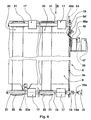
- Transport table 8 (see in particular Figs. 2, 5 and 6) comprises a U-shaped support 9 with limiting walls 9a, 9b, bent upward at an angle, which is installed parallel to transport directions "B" and "D" (see Fig. 11).
- Lower shafts 18, 19 and superposed parallel shafts 15, 16 are rotatably mounted to limiting walls 9a, 9b.
- Pairs of transport rollers 17, 20 are mounted opposite each other on shafts 15, 16, 18, 19.
- Shafts 15, 18 are associated with the front end of transport table 8 associated with units (1 and 2, respectively), whereas shafts 16, 19 are associated with the opposite rear end.
- Guide rollers 21 supporting continuous transport belts 22 are mounted to lower shafts 18, 19 between pairs of transport rollers 17, 20.
- Upper shafts 15, 16 are spring-biased against lower shafts 18, 19 in a conventional, not illustrated, manner.
- Fig. 2 shows that support 9 of transport table 8 can be pivoted on support sites 23b, 23c by means of lower rear shaft 19 and is fixed in axial direction by a carriage projection 23a) (see Fig. 6) which fits into a recess 9c on the bottom of support 9.
- a carriage projection 23a (see Fig. 6) which fits into a recess 9c on the bottom of support 9.
- support sites 23b, 23c are open toward the top, the entire transport table 8 may be removed easily.
- Fig. 7 shows guideway 14 inclined at an angle a relative to the horizontal plane.
- Guideway 14 extends from output opening 1b of loading/unloading unit 1 to input opening 2b of processing unit 2 and its endpoints can be adjusted in vertical direction by conventional not illustrated means. This feature allows the adjustment of guideway 14 in different angular positions as well as in a not illustrated opposite inclined position different from that of Fig. 7.
- said transport table When guideway 14 is in the inclined position subtending angle a, said transport table can be moved into the transport plane of output opening 1b and input opening 2b located at different vertical distances from the installation surface of units 1 and 2.
- the vertical pivoting motion of transport table 8 can be adapted to the individual height of input opening 2b of processing unit 2 which, depending on the type of unit, may be above or below output opening 1b of loading/unloading unit 1. Furthermore, this feature of being able to adjust guideway 14 allows a convenient optional right/left association of units 1 and 2.
- Photoelectric barriers 39, 40 which may be adjusted in a conventional not illustrated manner, are mounted on holders 41, 42 in the respective end zones of guideway 14.
- cover flags 47, 48 and 49, 56 associated with photoelectric barriers 39, 40.
- Said cover flags 47, 48 and 49, 56 are located at a distance from each other in the direction of movement of carriage 23, whereby cover flags 47, 49 are rigidly mounted, while cover flags 48, 56 can be pivoted in horizontal direction. Pivoting cover flags 48, 56 are mounted to a flexible elastic arm 48a (shown for one side only) with an activating pin 48b, 56a extension.
- Said activating pin 48b, 56a extends through an opening (9d) of limiting wall 9a, 9b into the transport zone of the sheet film and, in a still to be described manner, controls the position of the film exiting the loading/unloading unit 1 to assure the appropriate orientation with respect to input opening 2b of processing unit 2.
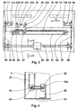
- FIG. 3 shows, in particular, stationary rotating one-way jaw clutches 10, 11 driven together by shaft 35a over drawing means 37, 45 guided on wheels 43, 44 and 36, 46.
- Drawing means 34 facilitates the engagement of drive shaft 35a (see Fig. 4) with drive shaft 33a of motor 33.
- One-way jaw clutches 10, 11 can be moved in axial direction against a spring bias, thereby creating a compensation for different back-and-forth movements of transport table 8.
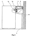
- Fig. 8 shows transport table 8 in its first end position in which it is positioned in the extension of output opening 1a of loading/unloading unit 1 in such a manner that its front end 17, 20 is in the transport plane of transport means 1c.
- the ejected sheet film is then be gripped by transport rollers 17, 20 and transported on transport belts 22 which are driven in the same sense of direction.
- transport rollers 17, 20 When - viewed perpendicular to transport direction "B" - a particularly wide sheet film 54 (only indicated in Fig. 6) arrives on transport table 8, it is assured that said wide sheet film 54 can later enter the relatively narrow input opening 2b of processing unit 2 in an appropriately centered manner.
- motor 33 is deenergized so that shaft 35a, and therefore the entire transport on transport table, 8 is stopped.
- motor 29 is energized and moves carriage 23 in the direction of arrow "C" until transport table 8 hinged to the latter assumes its second end position (home position) shown in Fig. 9.
- transport table 8 moves in the direction of arrow "C” its front end (transport rollers 17, 20 is pivoted over the inclined guideway 14 up to a level where transport table 8 is positioned in its second end position representing the extension to input opening 2b of processing unit 2 or the interposed adapter 4 (see Fig. 9).
- Adapter 4 on the input side of processing unit 2 mainly bridges the small unit depth of processing unit 2; as a result of this the front sides of both adjacent units 1 and 2 will be on substantially the same plane.
- the input sheet film is treated in a conventional not illustrated manner and then ejected through film output opening 2a into receiving tray 2d.
- the input of the exposed sheet film and the output of the processed finished sheet film take place in a particularly convenient manner on the same adjacent coplanar front of units 1 and 2.
- motor 29 is started by not illustrated means.
- said motor effects the reverse transport of carriage 23 and hence of transport table 8 (opposite the direction of arrow "C", see Fig. 11) into the first end position of said loading/unloading unit.
- the front end (transport rollers 17, 20 of transport table 8 is lowered over the inclined surface of guideway 14 to a level (see Fig. 8) at which the transport plane of transport table 8 again becomes the extension of transport means 1c of loading/unloading unit 1.
- Rigid cover flag 49 reduces the travel speed of carriage 23 as it passes photoelectric barrier 40, thereby assuring that transport table 8 is stopped in an exact position opposite output opening 1b of loading/unloading unit 1 when pivoting cover flag 56 passes the photoelectric barrier and, as a result, switches off motor 29.
- film transport apparatus 3 is coupled with an input device 58 for exposed sheet film as shown by Figs. 10 and 11.
- Said input device permits the input of particularly long sheet films which cannot be fed into loading/unloading unit 1 directly and straight into processing unit 2.
- input device 52 offers an additional substantial advantage, that is, even when said loading/unloading unit may not be used due to maintenance, exposed sheet films may still be transported from the darkroom into processing unit 2 as described.
- Said installation and adjustment features on film transport apparatus 3 also permit the adaptation of guideway 14 to other vertical arrangements of input opening 2b of processing unit 2.
- input opening 2b is located in vertical direction below input opening 1b of loading/unloading unit 1. Departing from the example of embodiment shown in Fig. 7, this requires that guideway 14 be inclined toward the right, which can be achieved easily by appropriate installation and adjustment.
- Fig. 1 the particularly favorable arrangement of transport apparatus 3 leaves an open space below the latter which may accommodate, for example, a silver recovery unit 6 connected with processing unit 2 without requiring additional floor space.
Landscapes
- Physics & Mathematics (AREA)
- General Physics & Mathematics (AREA)
- Engineering & Computer Science (AREA)
- Mechanical Engineering (AREA)
- Sheets, Magazines, And Separation Thereof (AREA)
- Photographic Developing Apparatuses (AREA)
- Feeding Of Articles By Means Other Than Belts Or Rollers (AREA)
Description
- The invention herein relates to an apparatus for transporting sheet recording material, in particular sheet film, from a cassette loading/unloading unit to a processing unit comprising, interposed between the output opening of said loading/unloading unit and the input opening of said processing unit, a transport table which comprises driven transport means and bridges differences between the vertical positions of said output and input openings of said loading/unloading unit and said processing unit, respectively, and is selectively adapted so said openings.
- DE-37 18 131-C2 has disclosed a sheet film transport apparatus comprising a transport table which transports film sheets ejected by a cassette load-ing/unloading unit to a processing unit, whereby said transport table may be adapted selectively to different input/output openings of attached units. This apparatus, however, is suitable only for the straight, linear transport from the cassette loading/unloading unit to the processing unit requiring that these units be set up in sequence. This arrangement requires a large setup area due to the unit's overall depth and length and, furthermore, the apparatus' input and output sites are located at a distance and facing away from each other on opposite sides.
- The invention herein is to solve this problem by providing a transport apparatus as defined in the appended claims. The apparatus is constructed such that units connected with said apparatus may be set up in a space-saving and user-friendly manner next to each other and that, furthermore, a right/left association is achieved.
- In accordance with the present invention this has been accomplished in that
- the transport table can be moved back and forth along horizontally adjacent positions of output and input openings of the loading/unloading unit and the processing unit;
- the transport means of said transport table positioned in output and input transport directions can be driven in an output transport direction when said transport table is in a first end position associated with the output opening and in an input transport direction when said transport table is in a second end position associated with the input opening; and
- the front end of said transport table can be moved in a vertical direction such that it can be raised and lowered into the transport plane of said output and input openings, such as to face said input and output openings.
- Advantageously, said transport table is pivotally mounted to a carriage moved in horizontal direction in a manner allowing its front end facing said input or output opening to be raised or lowered into the transport plane of said input or output opening. In so doing, the front end of said transport table is supported by means of a rotatable wheel on a stationary guideway extending from the output opening of the processing unit to the input opening of said loading/unloading unit and being positioned in an inclined position compensating for the differences in height between said input and output openings.
- The transport means of said transport table comprise continuous transport belts and transport rollers guided on rotatably supported shafts. In an advantageous embodiment both ends of one of the shafts are provided with a dog which, in the first or second end position of said transport table, can be brought into engagement with a first or second one-way jaw clutch driven by a common drive comprising a reversible motor.
- Said transport table comprises a support for the shafts, transport belts and transport rollers provided with lateral limiting walls for the recording material. In an advantageous embodiment said limiting walls comprise resilient elastic activating pins extending into the transport zone of said recording material. Each of said activating pins located on both sides of said support controls a pivoting cover flag associated with a stationary photoelectric barrier such that said transport table is stopped in an operation-appropriate end position in which said recording material may run freely into the input opening of the processing unit.
- In a convenient embodiment said transport table and its guiding and driving means are accommodated in a light-tight housing which may be attached to the cassette loading/unloading and processing units. An adapter bridging different unit depths and comprising transport means in the transport plane of the respective unit is interposed between said housing and one of said units. The guideway for the wheel located on the front end of said transport table can be adjusted optionally inside said housing for various positions of inclination and height in order to adapt the vertical position of the input and output openings of the units. In addition, the overall vertical position of said housing may be adjusted to adapt it to said output and input openings of said units.
- Advantageously, the film transport apparatus can be set up to permit the right/left association of units if desired. An adaptation to the input and output openings of the units is possible irrespective of the vertical (higher or lower) position of the input opening of the processing unit relative to the output opening of the cassette loading/unloading unit.
- In an another advantageous form of embodiment of the invention herein the transport table housing may be docked to a darkroom-side input device for large-format recording material which cannot be handled by the loading/unloading unit. This input device, which may be attached to the rear side of said housing and extends into the darkroom, constitutes an extension of the transport plane when the transport table is in its end position associated with the processing unit, whereby a particularly straight and nondestructive film transport is achieved by the available transport table. Advantageously, the input device on the darkroom side may also be used for the input of films having other formats, for example, in instances of temporary unavailability of the cassette loading/unloading unit due to maintenance.
- The inventive embodiment and arrangement of the transport table is achieved advantageously in that the reliable and non-destructive transport of recording material becomes possible with optional right/left association of the units even when respective input and output openings of the units are in different vertical positions.
- Additional features and advantages are disclosed by the description of inventive examples of embodiment shown by the drawings and by subclaims. The following schematic drawings show in
- Fig. 1
- an assembly view of the film transport apparatus docked to a cassette loading/unloading unit as well as a processing unit;
- Fig. 2
- a sectional side view of the film transport apparatus of Fig. 1;
- Fig. 3
- a simplified sectional view of the film transport apparatus of Fig. 1 in longitudinal direction along line D-D, without the transport table;
- Fig. 4
- a sectional side view of part of the apparatus of Fig. 3 along line C-C;
- Fig. 5
- a partial sectional rear view in accordance with Fig. 2 along line A-A;
- Fig. 6
- a plan view of part of the apparatus of Fig. 2;
- Fig. 7
- the apparatus of Fig. 2 with a schematic illustration of the guideway position in longitudinal section along line B-B, without the transport table;
- Fig. 8
- the apparatus of Fig. 2 in the position on the cassette loading/unloading unit, partially in section;
- Fig. 9
- the apparatus of Fig. 2 in the position opposite the processing unit, including the interposed adapter, partially in section;
- Fig. 10
- another example of embodiment of the invention herein in accordance with Fig. 9 with an additional sheet film input device, partially in section; and
- Fig. 11
- a schematic plan view of the unit assembly in accordance with Fig. 1 and 10, respectively.
- The inventive
film transport apparatus 3 is described in conjunction with a commercially available loading/unloadingunit 1 for sheet film cassettes as disclosed by DE-37 05 951-C2.Film transport apparatus 3 connects said loading/unloading unit 1 with a commerciallyavailable processing unit 2 positioned directly adjacent the latter as shown by Fig. 1. - Referring to Figs. 1 and 11, the principle of operation of
apparatus units - A conventional, not illustrated, sheet film cassette containing exposed sheet film is inserted in the direction of arrow "A" in a
loading opening 1a on the front side of loading/unloading unit 1. Inside said unit said cassette is opened and the exposed sheet film taken out. The exposed sheet film is transported in the direction of arrow "B" by the unit's transport means 1c (see Fig. 8) to an output opening 1b on the rear side ofunit 1 and transported in the direction of arrow "C" insidefilm transport apparatus 3. Then the exposed sheet film is transported in the direction of arrow "D" through anadapter 4 and an input opening 2b intoprocessing unit 2. Once the exposed sheet film has passed throughprocessing unit 2 in a known not illustrated manner, the processed finished sheet film is ejected through a film output opening 2a into a receivingtray 2d on the front side ofprocessing unit 2. - The construction and operation of
film transport apparatus 3 will be described in detail hereinafter. -
Film transport apparatus 3 comprises a light-tight box-shaped housing 7 (see in particular Figs. 2, 8 and 9) such that its longitudinal side is docked in a light-tight manner to loading/unloadingunit 1 and, by means of anadapter 4, toprocessing unit 2. Adjustable supports 5 resting on the unit setup area support the opposite longitudinal side ofhousing 7.Housing 7 accommodates a transport table 8 on acarriage 23 which can be moved on astationary rail 28. As illustrated in a particularly clear manner in Fig. 2 and 3,guide rail 28 is mounted to an interior wall ofhousing 7 and has convex, horizontal as well as parallel, superposed runningsurfaces - Pairs of
rollers surfaces guide rail 28, allowing the movement ofcarriage 23.Carriage 23 is moved by drawing means 31 mounted to aprojection 23c ofcarriage 23. Said drawing means 31 is moved via adrive wheel 30 and guided by an additional,stationary wheel 32. Saiddrive wheel 30 is mounted to driveshaft 29a of astationary motor 29. - Above
rollers carriage 23 has twosupport sites surfaces guide rail 28. - Transport table 8 (see in particular Figs. 2, 5 and 6) comprises a
U-shaped support 9 with limitingwalls Lower shafts parallel shafts walls transport rollers shafts Shafts shafts Guide rollers 21 supportingcontinuous transport belts 22 are mounted tolower shafts transport rollers Upper shafts lower shafts - Fig. 2 shows that
support 9 of transport table 8 can be pivoted onsupport sites rear shaft 19 and is fixed in axial direction by acarriage projection 23a) (see Fig. 6) which fits into arecess 9c on the bottom ofsupport 9. Inasmuch assupport sites support sites guide rail 28 a favorable weight distribution ofcarriage 23 is achieved. - On the underside of
support 9 is anarm 12 associated with the front end of transport table 8, said arm supporting arotating wheel 13. Saidwheel 13 runs on aguideway 14 and supports the front end of transport table 8.Guideway 14 mounted tohousing 7 extends in longitudinal direction ofguide rail 28. However, Fig. 7 showsguideway 14 inclined at an angle a relative to the horizontal plane.Guideway 14 extends fromoutput opening 1b of loading/unloading unit 1 to input opening 2b ofprocessing unit 2 and its endpoints can be adjusted in vertical direction by conventional not illustrated means. This feature allows the adjustment ofguideway 14 in different angular positions as well as in a not illustrated opposite inclined position different from that of Fig. 7. - When
guideway 14 is in the inclined position subtending angle a, said transport table can be moved into the transport plane ofoutput opening 1b andinput opening 2b located at different vertical distances from the installation surface ofunits processing unit 2 which, depending on the type of unit, may be above or belowoutput opening 1b of loading/unloading unit 1. Furthermore, this feature of being able to adjustguideway 14 allows a convenient optional right/left association ofunits -
Photoelectric barriers holders guideway 14. - The exterior sides of both limiting
walls support 9 havecover flags photoelectric barriers carriage 23, whereby cover flags 47, 49 are rigidly mounted, while cover flags 48, 56 can be pivoted in horizontal direction. Pivoting cover flags 48, 56 are mounted to a flexibleelastic arm 48a (shown for one side only) with an activatingpin pin wall unloading unit 1 to assure the appropriate orientation with respect to input opening 2b ofprocessing unit 2. - Each end of
lower shaft 9 of transport table 8 has arecess 19a acting as dog. One-way jaw clutches dogs recesses 19a ofshaft 19 are located on both end positions of transport table 8. Fig. 3 shows, in particular, stationary rotating one-way jaw clutches wheels drive shaft 33a ofmotor 33. One-way jaw clutches - Fig. 8 shows transport table 8 in its first end position in which it is positioned in the extension of
output opening 1a of loading/unloading unit 1 in such a manner that itsfront end - A not illustrated cassette containing exposed sheet film is inserted in
loading opening 1a of loading/unloading unit 1 in the direction of arrow "A" (see Fig. 11). As described, the cassette is opened inside the unit, the exposed film removed and ejected by transport means 1c through therear output opening 1b of loading/unloading unit 1. Not illustrated sensors detect the leading edge of the sheet film in a manner known per se and activatemotor 33 which drivesshaft 19 over one-way jaw clutch 10 and hence the pairs oftransport rollers - The ejected sheet film is then be gripped by
transport rollers transport belts 22 which are driven in the same sense of direction. When - viewed perpendicular to transport direction "B" - a particularly wide sheet film 54 (only indicated in Fig. 6) arrives on transport table 8, it is assured that saidwide sheet film 54 can later enter the relatively narrow input opening 2b ofprocessing unit 2 in an appropriately centered manner. - Activating
pin 48b of pivotingcover flag 48 achieves this in the situation shown by Fig. 6 by extending into the path of movement of the right edge ofsheet film 54 thereby pivoting said sheet film into the position indicated by the chain line. As a result, coverflag 48 moves, as indicated, into a different home position relative to photoelectric barrier 39 (indicated in Fig. 6 for clarification) associated with a second, still to be described, end position of transport table 8. - As soon as the sensor detects the trailing edge of
sheet film 54motor 33 is deenergized so that shaft 35a, and therefore the entire transport on transport table, 8 is stopped. At thesame time motor 29 is energized and movescarriage 23 in the direction of arrow "C" until transport table 8 hinged to the latter assumes its second end position (home position) shown in Fig. 9. As transport table 8 moves in the direction of arrow "C" its front end (transport rollers inclined guideway 14 up to a level where transport table 8 is positioned in its second end position representing the extension to input opening 2b ofprocessing unit 2 or the interposed adapter 4 (see Fig. 9). - Before reaching this second end position, said
first cover flag 47 of transport table 8 passesphotoelectric barrier 39, thereby initiating a reduction of the travel speed ofcarriage 23. In so doing, therecess 19a ofshaft 19 comes into engagement withdog 11a of one-way jaw clutch 11, whereby the axial movement of the latter allows its reliable engagement in different end positions of transport table 8. -
Adapter 4 on the input side ofprocessing unit 2 mainly bridges the small unit depth ofprocessing unit 2; as a result of this the front sides of bothadjacent units - Relative to
photoelectric barrier 39,carriage 23 is stopped in the second end position somewhat earlier becausecover flag 48 pivoted to the right bysheet film 54 has already reachedphotoelectric barrier 39 as described and indicated in Fig. 6. Due to this,sheet film 54 is positioned opposite input opening 2b in an exact position such that said film may be transported without disruption intoprocessing unit 2. - On its path into
processing unit 2 said sheet film passes first throughadapter 4. The leading edge ofsheet film 54 enters the nip of the first pair of rollers 51 (see Fig. 9) ofadapter 4 thereby lifting the upper roller of the latter and activating a switch which starts a driving motor (not illustrated). By means of a not illustrated one-way clutch said driving motor drives the lower roller of a second pair ofrollers 55 which is connected by drawing means with the lower roller of said first pair ofrollers 51. The transport speed inadapter 4 initially corresponds to that of transport table 8. Before the leading edge ofsheet film 54 reaches film transport means 2c ofprocessing unit 2, the input transport speed is reduced sufficiently in a known not illustrated manner to allowsheet film 54 to be drawn by film transport means 2c intoprocessing unit 2. The one-way clutches ofadapter 4 and transport table 8 assure that said sheet film can be drawn freely by the transport means of the latter intoprocessing unit 2. - Inside
processing unit 2 the input sheet film is treated in a conventional not illustrated manner and then ejected throughfilm output opening 2a into receivingtray 2d. - As shown by Fig. 1 and 11 in particular, the input of the exposed sheet film and the output of the processed finished sheet film take place in a particularly convenient manner on the same adjacent coplanar front of
units - After the sheet film's trailing edge has left
film transport rollers motor 29 is started by not illustrated means. By being reversed, said motor effects the reverse transport ofcarriage 23 and hence of transport table 8 (opposite the direction of arrow "C", see Fig. 11) into the first end position of said loading/unloading unit. In so doing, the front end (transport rollers guideway 14 to a level (see Fig. 8) at which the transport plane of transport table 8 again becomes the extension of transport means 1c of loading/unloading unit 1. As transport table 8 moves on its path in the direction opposite arrow "C", coverflags photoelectric barrier 14.Rigid cover flag 49 reduces the travel speed ofcarriage 23 as it passesphotoelectric barrier 40, thereby assuring that transport table 8 is stopped in an exact positionopposite output opening 1b of loading/unloading unit 1 when pivotingcover flag 56 passes the photoelectric barrier and, as a result, switches offmotor 29. - In an expanded embodiment of the invention herein
film transport apparatus 3 is coupled with an input device 58 for exposed sheet film as shown by Figs. 10 and 11. Said input device permits the input of particularly long sheet films which cannot be fed into loading/unloading unit 1 directly and straight intoprocessing unit 2. -
Input device 52 mounted to the rear wall offilm transport apparatus 3 communicates throughopening 7c (see Figs. 3 and 11) with transport table 8 positioned in its home position opposite input opening 2a ofprocessing unit 2.Input device 52 extends through a light-tight opening 57a of awall 57 into a not illustrated darkroom and is operator-controlled from there.Input device 52 comprises a pivotable, hingedcover 52a which is closed after a sheet film removed from a cassette in the darkroom has been inserted. The inserted sheet film is advanced in the direction of arrow "F" as shown by Fig. 11. In so doing, the leading edge of the sheet film activates a not illustratedswitch energizing motor 33 to driveshaft 19, whereupon the film transport proceeds as described in the direction of arrow "D" intoprocessing unit 2. - Beyond the described purpose of use,
input device 52 offers an additional substantial advantage, that is, even when said loading/unloading unit may not be used due to maintenance, exposed sheet films may still be transported from the darkroom intoprocessing unit 2 as described. - Departing from the apparatus setup shown by Figs. 1, 7 and 11, the left/right arrangement may be reversed easily, should this be desirable. This (not illustrated) simply requires that
adapter 4 be installedopposite processing unit 2 located on the other side and thatguideway 14 be inclined appropriately in opposite direction. The necessary installation and adjustment means (not illustrated) are provided onfilm transport apparatus 3 andadapter 4. Considering this reversed right/left association ofunits cover flag 56 assures accurate positioning of the sheet film relative toprocessing unit 2 in that activatingpin 56a can be pivoted by the sheet film which is transported out of loading/unloading unit 1. - Said installation and adjustment features on
film transport apparatus 3 also permit the adaptation ofguideway 14 to other vertical arrangements of input opening 2b ofprocessing unit 2. For example, in another commercially available (not illustrated) processing unit saidinput opening 2b is located in vertical direction below input opening 1b of loading/unloading unit 1. Departing from the example of embodiment shown in Fig. 7, this requires thatguideway 14 be inclined toward the right, which can be achieved easily by appropriate installation and adjustment. - In another commercially available (not illustrated) processing unit said
input opening 2b is located in vertical direction belowoutput opening 1b of loading/unloading unit 1 such thatguideway 14 would have to be inclined steeply. In order to prevent this, theentire housing 7 offilm transport apparatus 3 can be adjusted by not illustrated means, thus making an adaptation to special conditions possible as well. - As is shown by Fig. 1 the particularly favorable arrangement of
transport apparatus 3 leaves an open space below the latter which may accommodate, for example, asilver recovery unit 6 connected withprocessing unit 2 without requiring additional floor space.
Claims (14)
- Apparatus for transporting sheet recording material, in particular sheet film, from a cassette loading/unloading unit to a processing unit comprising, interposed between the output opening of said loading/unloading unit and the input opening of said processing unit, a transport table which comprises driven transport means and bridges differences between the vertical positions of said output and input openings of said loading/unloading unit and said processing unit, respectively, and is selectively adapted so said openings, characterized in thatthe transport table (8) is adapted to be moved back and forth along horizontally adjacent positions of said output and input openings (1b, 2b) of the loading/unloading unit (1) and the processing unit (2);the transport means (17, 20, 22) of transport table (8) positioned in output and input transport directions (B, D) are adapted to be driven in output transport direction (B) when said transport table (8) is in a first end position associated with output opening (1b) and in an input transport direction (D) when said transport table (8) is in a second end position associated with input opening (2b); andthe front end (17, 20) of the transport table (8) can be moved in a vertical direction such that it can be raised and lowered into the transport planes of said output and input openings (1b, 2b) such as to face said input and output openings (1b, 2b).
- Apparatus in accordance with Claim 1, characterized in thatthe transport table (8) transporting the recording material in a substantially flat manner can be pivoted in vertical direction so that its front end (17, 20) facing output and input openings (1b, 2b) can be raised and lowered into the transport plane of said output and input openings (1b, 2b); andthat its rear end (19) facing away from output and input openings (1b, 2b) can be pivoted in vertical direction about a stationary support (23b, 23c).
- Apparatus in accordance with Claim 2, characterized in thata rotatable wheel (13) supported by a stationary guideway (14) is mounted to the front end of transport table (8);guideway (14) extends from output opening (1b) of loading/unloading unit (1) to input opening (2b) of processing unit (2);guideway (14) extends along path of movement (C) of transport table (8) at an inclination (a) controlling the vertical pivot path of the front end (17, 20) of transport table (8); andtransport table (8) is movably guided by its rear end (19) in horizontal direction.
- Apparatus in accordance with Claim 2 or 3, characterized in that stationary supports (23b, 23c) for the rear end (19) of transport table (8) are mounted on a horizontally guided carriage (23) which is moved by a reversible motor (29) into respective end positions.
- Apparatus in accordance with Claim 4, characterized in thatparallel, as well as vertically superposed, pairs of moving rollers (24, 25; 26, 27) having concave running surfaces are rotatably supported on carriage (23) in the rear end (19) portion of transport table (8); andmoving rollers (24 through 27) move in a form-closed manner over a guide rail (28) having parallel, convex running surfaces (28a, 28b) extending in horizontal direction between pairs of moving rollers (24, 25; 26, 27).
- Apparatus in accordance with Claim 5, characterized in that a drawing means (31) guided on rotating wheels (30, 32) is fastened to carriage (23) parallel to guide rail (28), and that one of said wheels (30) can be driven by a reversible motor (29) in order to move said drawing means (31) and said carriage (23).
- Apparatus in accordance with one of the Claims 1 through 6, characterized in thatthe transport means of transport table (8) comprise endless transport belts (22) which are guided on first rotatably supported shafts (16, 19) and guide rollers (21, 22);second, rotatable shafts (15, 18), which are spring-biased against said first shafts (16, 19), are provided above said first shafts (16, 19) and parallel to said first shafts;pairs of transport rollers (17, 20) opposite each other and in contact with each other are mounted to shafts (15, 16, 18, 19);transport belts (22) are provided between pairs of transport rollers (17, 20); andfirst shaft (19) associated with the rear end of transport table (8) has on each of its end sides a dog (19a) which can be brought into engagement with a driving device (10, 32 to 37, 46; 11, 33 to 35, 43 to 45) in first and second end positions of transport table (8).
- Apparatus in accordance with Claim 7, characterized in thatthe driving device for transport table (8) comprises driven one-way jaw clutches (10; 11) which are mounted rotatably at each end position of transport table (8) and brought into engagement with dog (19a) associated with first shaft (19); andsaid one-way jaw clutches (10; 11) are in engagement with drawing means (37, 45) which are driven over a joint drive shaft (35) by a reversible motor (33).
- Apparatus in accordance with Claim 7 or 8, characterized in thatshafts (15, 16, 18, 19) of transport table (8) are rotatably supported by a support (9);support (9) comprises lateral limiting walls (9a, 9b) parallel to transport direction (B; D) guiding the recording material;two cover flags (47, 48; 49, 56) are mounted in sequence at a distance from each other in the direction of movement of carriage (23), whereby said flags are associated with stationary photoelectric barriers (39, 40) provided at the end positions of transport table (8);one of said cover flags (48, 56) is mounted to a flexible elastic arm (48a); andsaid flexible elastic arm (48a) comprises an activating pin (48b, 56a) extending through opening (9d) of the respective limiting wall (9a, 9b) into the transport zone of the recording material.
- Apparatus in accordance with one or several of Claims 1 through 9, characterized in that transport table (8) and its guiding and driving means (9 through 49) are accommodated in a light-tight housing (7) which can be mounted to cassette loading/unloading unit (1) and processing unit (2) and can be adjusted selectively in vertical direction relative to the units' output and input openings (1b; 2b).
- Apparatus in accordance with one of the Claims 3 through 10, characterized in that the inclination and/or elevation of guideway (14) in housing (7) can be adjusted selectively.
- Apparatus in accordance with Claim 10 or 11, characterized in that, on the side of housing (7) facing processing unit (2) and loading/unloading unit (1), an opening (7a) is provided in the transport plane of the respective input and output openings (1b; 2b) of units (1; 2) constituting an extension of the respective end positions of transport table (8), and that an adapter (4) can be attached to opening (7a) in order to bridge different unit depths for transport of the recording material between transport table (8) and the respective unit (1; 2).
- Apparatus in accordance with Claim 12, characterized in that driven pairs of transport rollers (51, 55) are provided in the transport plane ahead of unit transport means (51).
- Apparatus in accordance with Claims 10 through 13, characterized in that, on the side of processing unit (2) facing the rear side of housing (7), an opening (7c; 7d) associated with input opening (2b) of processing unit (2) and constituting an extension of the transport plane of the associated end position of transport table (8) is provided for the light-tight attachment of a darkroomside input device (52) for large-format recording material.
Applications Claiming Priority (3)
| Application Number | Priority Date | Filing Date | Title |
|---|---|---|---|
| DE4417050A DE4417050A1 (en) | 1994-05-14 | 1994-05-14 | Device for transporting sheet-like recording material |
| DE4417050 | 1994-05-14 | ||
| US08/439,326 US5660383A (en) | 1994-05-14 | 1995-05-11 | Sheet recording material transport apparatus |
Publications (2)
| Publication Number | Publication Date |
|---|---|
| EP0682290A1 EP0682290A1 (en) | 1995-11-15 |
| EP0682290B1 true EP0682290B1 (en) | 2002-11-20 |
Family
ID=25936610
Family Applications (1)
| Application Number | Title | Priority Date | Filing Date |
|---|---|---|---|
| EP95106714A Expired - Lifetime EP0682290B1 (en) | 1994-05-14 | 1995-05-04 | Sheet recording material transport apparatus |
Country Status (4)
| Country | Link |
|---|---|
| US (1) | US5660383A (en) |
| EP (1) | EP0682290B1 (en) |
| JP (1) | JPH0859010A (en) |
| DE (1) | DE4417050A1 (en) |
Families Citing this family (9)
| Publication number | Priority date | Publication date | Assignee | Title |
|---|---|---|---|---|
| DE19745012A1 (en) | 1997-10-11 | 1999-04-15 | Eastman Kodak Co | X-ray film cartridge transport arrangement |
| DE10044245C2 (en) * | 2000-09-07 | 2002-11-14 | Agfa Gevaert Ag | Apparatus and method for processing light-sensitive material |
| DE10044247C2 (en) * | 2000-09-07 | 2002-10-31 | Agfa Gevaert Ag | Apparatus and method for processing light-sensitive material |
| DE10044250C2 (en) * | 2000-09-07 | 2003-04-30 | Agfa Gevaert Ag | Apparatus and method for loading a storage medium for light-sensitive material |
| DE102004013898A1 (en) * | 2004-03-22 | 2005-10-13 | Eastman Kodak Co. | Boom for a printing machine |
| DE102007020778A1 (en) * | 2007-05-03 | 2008-11-06 | Giesecke & Devrient Gmbh | Device for handling value documents |
| US8408545B2 (en) * | 2009-11-25 | 2013-04-02 | Perfect Systems, Llc | Auxiliary feed conveyor |
| US9516357B2 (en) * | 2010-09-10 | 2016-12-06 | Verizon Patent And Licensing Inc. | Recording variable-quality content stream |
| EP2784758B1 (en) * | 2013-03-27 | 2017-08-30 | Wincor Nixdorf International GmbH | Adjusting device for self-service devices and adjustment method |
Family Cites Families (8)
| Publication number | Priority date | Publication date | Assignee | Title |
|---|---|---|---|---|
| GB1081566A (en) * | 1965-04-03 | 1967-08-31 | Gunter Mattka | A sheet delivering machine |
| DE3309266A1 (en) * | 1983-03-15 | 1984-09-20 | Siemens AG, 1000 Berlin und 8000 München | Device for unloading sheet film magazines |
| DE3705851A1 (en) * | 1987-02-24 | 1988-09-01 | Kodak Ag | AUTOMATIC FILM INSERTING DEVICE FOR SHEET FILM CARTRIDGES |
| DE3718131A1 (en) * | 1987-05-29 | 1988-12-15 | Kodak Ag | Device for transporting film sheets |
| JP2811019B2 (en) * | 1989-05-02 | 1998-10-15 | コニカ株式会社 | Film processing equipment |
| DE4130563C1 (en) * | 1991-09-13 | 1993-01-07 | Agfa-Gevaert Ag, 5090 Leverkusen, De | |
| DE4232733A1 (en) * | 1992-09-30 | 1994-03-31 | Duerr Dental Gmbh Co Kg | Transport unit between photographic exposure and developer units - has pivoted transport rollers and guide plates allowing temporary storage of exposed sheets |
| US5326093A (en) * | 1993-05-24 | 1994-07-05 | Xerox Corporation | Universal interface module interconnecting various copiers and printers with various sheet output processors |
-
1994
- 1994-05-14 DE DE4417050A patent/DE4417050A1/en not_active Withdrawn
-
1995
- 1995-05-04 EP EP95106714A patent/EP0682290B1/en not_active Expired - Lifetime
- 1995-05-11 US US08/439,326 patent/US5660383A/en not_active Expired - Fee Related
- 1995-05-15 JP JP7115590A patent/JPH0859010A/en active Pending
Also Published As
| Publication number | Publication date |
|---|---|
| JPH0859010A (en) | 1996-03-05 |
| DE4417050A1 (en) | 1995-11-16 |
| US5660383A (en) | 1997-08-26 |
| EP0682290A1 (en) | 1995-11-15 |
Similar Documents
| Publication | Publication Date | Title |
|---|---|---|
| US7207250B2 (en) | Process and device for moving and positioning sheets of glass | |
| US5660383A (en) | Sheet recording material transport apparatus | |
| US4285512A (en) | Document feed device | |
| US5299033A (en) | Image reading and recording apparatus with marking board and moveable scanning arm conveyed by a cable and drum arrangement | |
| US4236709A (en) | Cartridge sheet feed attachment | |
| JPH0215447B2 (en) | ||
| JPS6157253B2 (en) | ||
| JPH04226238A (en) | Film sheet aligning mechanism | |
| US6278126B2 (en) | Transport device for X-ray cassettes, each having a phosphor sheet stimulable by X-rays, in a cassette processing apparatus | |
| JPH02198947A (en) | Image forming device | |
| EP1130471A2 (en) | Exposure apparatus for printing plates | |
| JP2727110B2 (en) | Belt type conveyor | |
| JPS62166990A (en) | Cutter | |
| JP2845067B2 (en) | Traveling trolley | |
| JPH0891554A (en) | Overhead type small article high-speed carrying device | |
| JPH0626424B2 (en) | Image scanning device | |
| JPH0534261B2 (en) | ||
| JPS628375B2 (en) | ||
| JPH0543066A (en) | Paper feeding device | |
| JPS6331947A (en) | Feeding and discharging device for sheet-shaped original | |
| JP2734812B2 (en) | Overhead traveling vehicle with reversing mechanism | |
| JPH0512258B2 (en) | ||
| JPH0611982Y2 (en) | Paper transport mechanism of image forming apparatus | |
| JPS62166991A (en) | Cutter | |
| JPH0479936B2 (en) |
Legal Events
| Date | Code | Title | Description |
|---|---|---|---|
| PUAI | Public reference made under article 153(3) epc to a published international application that has entered the european phase |
Free format text: ORIGINAL CODE: 0009012 |
|
| AK | Designated contracting states |
Kind code of ref document: A1 Designated state(s): DE FR GB |
|
| 17P | Request for examination filed |
Effective date: 19960418 |
|
| GRAG | Despatch of communication of intention to grant |
Free format text: ORIGINAL CODE: EPIDOS AGRA |
|
| 17Q | First examination report despatched |
Effective date: 20020322 |
|
| GRAG | Despatch of communication of intention to grant |
Free format text: ORIGINAL CODE: EPIDOS AGRA |
|
| GRAH | Despatch of communication of intention to grant a patent |
Free format text: ORIGINAL CODE: EPIDOS IGRA |
|
| GRAH | Despatch of communication of intention to grant a patent |
Free format text: ORIGINAL CODE: EPIDOS IGRA |
|
| GRAA | (expected) grant |
Free format text: ORIGINAL CODE: 0009210 |
|
| AK | Designated contracting states |
Kind code of ref document: B1 Designated state(s): DE FR GB |
|
| PG25 | Lapsed in a contracting state [announced via postgrant information from national office to epo] |
Ref country code: FR Free format text: LAPSE BECAUSE OF FAILURE TO SUBMIT A TRANSLATION OF THE DESCRIPTION OR TO PAY THE FEE WITHIN THE PRESCRIBED TIME-LIMIT Effective date: 20021120 |
|
| REG | Reference to a national code |
Ref country code: GB Ref legal event code: FG4D |
|
| REF | Corresponds to: |
Ref document number: 69528857 Country of ref document: DE Date of ref document: 20030102 |
|
| PG25 | Lapsed in a contracting state [announced via postgrant information from national office to epo] |
Ref country code: DE Free format text: LAPSE BECAUSE OF FAILURE TO SUBMIT A TRANSLATION OF THE DESCRIPTION OR TO PAY THE FEE WITHIN THE PRESCRIBED TIME-LIMIT Effective date: 20030221 |
|
| PG25 | Lapsed in a contracting state [announced via postgrant information from national office to epo] |
Ref country code: GB Free format text: LAPSE BECAUSE OF NON-PAYMENT OF DUE FEES Effective date: 20030504 |
|
| EN | Fr: translation not filed | ||
| PLBE | No opposition filed within time limit |
Free format text: ORIGINAL CODE: 0009261 |
|
| STAA | Information on the status of an ep patent application or granted ep patent |
Free format text: STATUS: NO OPPOSITION FILED WITHIN TIME LIMIT |
|
| 26N | No opposition filed |
Effective date: 20030821 |
|
| GBPC | Gb: european patent ceased through non-payment of renewal fee |
Effective date: 20030504 |