EP0681963A1 - Divider for foldable cardboard boxes and a method for manufacturing said divider - Google Patents
Divider for foldable cardboard boxes and a method for manufacturing said divider Download PDFInfo
- Publication number
- EP0681963A1 EP0681963A1 EP95500069A EP95500069A EP0681963A1 EP 0681963 A1 EP0681963 A1 EP 0681963A1 EP 95500069 A EP95500069 A EP 95500069A EP 95500069 A EP95500069 A EP 95500069A EP 0681963 A1 EP0681963 A1 EP 0681963A1
- Authority
- EP
- European Patent Office
- Prior art keywords
- divider
- glued
- sheets
- strips
- box
- Prior art date
- Legal status (The legal status is an assumption and is not a legal conclusion. Google has not performed a legal analysis and makes no representation as to the accuracy of the status listed.)
- Granted
Links
Images

Classifications
-
- B—PERFORMING OPERATIONS; TRANSPORTING
- B65—CONVEYING; PACKING; STORING; HANDLING THIN OR FILAMENTARY MATERIAL
- B65D—CONTAINERS FOR STORAGE OR TRANSPORT OF ARTICLES OR MATERIALS, e.g. BAGS, BARRELS, BOTTLES, BOXES, CANS, CARTONS, CRATES, DRUMS, JARS, TANKS, HOPPERS, FORWARDING CONTAINERS; ACCESSORIES, CLOSURES, OR FITTINGS THEREFOR; PACKAGING ELEMENTS; PACKAGES
- B65D5/00—Rigid or semi-rigid containers of polygonal cross-section, e.g. boxes, cartons or trays, formed by folding or erecting one or more blanks made of paper
- B65D5/42—Details of containers or of foldable or erectable container blanks
- B65D5/44—Integral, inserted or attached portions forming internal or external fittings
- B65D5/48—Partitions
- B65D5/48024—Partitions inserted
- B65D5/48026—Squaring or like elements, e.g. honeycomb element, i.e. at least four not aligned compartments
-
- B—PERFORMING OPERATIONS; TRANSPORTING
- B31—MAKING ARTICLES OF PAPER, CARDBOARD OR MATERIAL WORKED IN A MANNER ANALOGOUS TO PAPER; WORKING PAPER, CARDBOARD OR MATERIAL WORKED IN A MANNER ANALOGOUS TO PAPER
- B31D—MAKING ARTICLES OF PAPER, CARDBOARD OR MATERIAL WORKED IN A MANNER ANALOGOUS TO PAPER, NOT PROVIDED FOR IN SUBCLASSES B31B OR B31C
- B31D3/00—Making articles of cellular structure, e.g. insulating board
- B31D3/002—Methods for making cellular structures; Cellular structures
-
- B—PERFORMING OPERATIONS; TRANSPORTING
- B31—MAKING ARTICLES OF PAPER, CARDBOARD OR MATERIAL WORKED IN A MANNER ANALOGOUS TO PAPER; WORKING PAPER, CARDBOARD OR MATERIAL WORKED IN A MANNER ANALOGOUS TO PAPER
- B31D—MAKING ARTICLES OF PAPER, CARDBOARD OR MATERIAL WORKED IN A MANNER ANALOGOUS TO PAPER, NOT PROVIDED FOR IN SUBCLASSES B31B OR B31C
- B31D3/00—Making articles of cellular structure, e.g. insulating board
- B31D3/04—Making articles of cellular structure, e.g. insulating board cellular packaging articles, e.g. for bottles
-
- B—PERFORMING OPERATIONS; TRANSPORTING
- B31—MAKING ARTICLES OF PAPER, CARDBOARD OR MATERIAL WORKED IN A MANNER ANALOGOUS TO PAPER; WORKING PAPER, CARDBOARD OR MATERIAL WORKED IN A MANNER ANALOGOUS TO PAPER
- B31D—MAKING ARTICLES OF PAPER, CARDBOARD OR MATERIAL WORKED IN A MANNER ANALOGOUS TO PAPER, NOT PROVIDED FOR IN SUBCLASSES B31B OR B31C
- B31D5/00—Multiple-step processes for making three-dimensional [3D] articles
- B31D5/0004—Multiple-step processes for making three-dimensional [3D] articles for making inserts, e.g. partitions, for boxes
-
- B—PERFORMING OPERATIONS; TRANSPORTING
- B31—MAKING ARTICLES OF PAPER, CARDBOARD OR MATERIAL WORKED IN A MANNER ANALOGOUS TO PAPER; WORKING PAPER, CARDBOARD OR MATERIAL WORKED IN A MANNER ANALOGOUS TO PAPER
- B31B—MAKING CONTAINERS OF PAPER, CARDBOARD OR MATERIAL WORKED IN A MANNER ANALOGOUS TO PAPER
- B31B2120/00—Construction of rigid or semi-rigid containers
- B31B2120/20—Construction of rigid or semi-rigid containers provided with two or more compartments
- B31B2120/25—Construction of rigid or semi-rigid containers provided with two or more compartments formed by partitions or like inserts not integral with walls
-
- Y—GENERAL TAGGING OF NEW TECHNOLOGICAL DEVELOPMENTS; GENERAL TAGGING OF CROSS-SECTIONAL TECHNOLOGIES SPANNING OVER SEVERAL SECTIONS OF THE IPC; TECHNICAL SUBJECTS COVERED BY FORMER USPC CROSS-REFERENCE ART COLLECTIONS [XRACs] AND DIGESTS
- Y10—TECHNICAL SUBJECTS COVERED BY FORMER USPC
- Y10T—TECHNICAL SUBJECTS COVERED BY FORMER US CLASSIFICATION
- Y10T156/00—Adhesive bonding and miscellaneous chemical manufacture
- Y10T156/10—Methods of surface bonding and/or assembly therefor
- Y10T156/1002—Methods of surface bonding and/or assembly therefor with permanent bending or reshaping or surface deformation of self sustaining lamina
- Y10T156/1003—Methods of surface bonding and/or assembly therefor with permanent bending or reshaping or surface deformation of self sustaining lamina by separating laminae between spaced secured areas [e.g., honeycomb expanding]
Definitions
- the present invention refers to a divider for foldable cardboard boxes and a method for manufacturing said divider, made up of an assembly of sheets of cardboard or other similar material, joined to each other in perpendicular positions so that they make up small cells or compartments for holding bottles or similar fragile objects, perfectly separated from each other.
- dividers for foldable cardboard boxes formed by assemblies of sheets or strips provided with complementary cuts for slotting in the intercrossed sheets.
- these known embodiments only some of the sheets are glued to an internal side of the box; the other sheets are attached only to those which are glued to the box, but are not themselves attached to it.
- dividers are configured in such a way that they are folded at the same time as the box, though the fact that not all the sheets are attached to the sides thereof provokes that the divider moves out of its correct position, which creates difficulties for folding and unfolding it.
- Another type of known divider is made up of a plurality of cardboard sheets provided with cutting lines and folding lines which serve to form flaps and strips in directions perpendicular to the flaps, those of one sheet being glued to those of the sheet immediately adjacent to it, so that they can be folded and unfolded at will, while the strips of the sheets situated at the ends of the assembly are glued to the sides of the box.
- dividers have advantages over the traditional dividers formed by sheets or strips with cuts to slot them into intercrossed position, they are rather slow to manufacture and the process must be implemented using precut sheets which are later submitted to a process of die-cutting, folding and gluing.
- the known dividers are usually formed from ridged cardboard sheets whose rigidity prevents feed from bobbins, for which reason supply must be implemented as stated above, in the form of precut sheets, which means that the entire manufacturing process cannot be implemented continuously.
- the divider for cardboard boxes and a method for manufacturing the divider object of the present invention have been designed in order to solve the disadvantages outlined.
- the divider is made up of an assembly of strips or sheets of cardboard or similar material arranged in positions perpendicular to each other to form a plurality of compartments, at least some of which sheets or strips can be glued onto two opposite sides of the box.
- the divider is characterized in that it comprises an assembly of sheets provided with transverse fold lines, which make up bands folded in perpendicular directions with respect to bands juxtaposed and glued to the immediately adjacent sheets.
- the ends of the sheets which are situated on at least two opposite sides of the assembly are provided with flap-like bands folded transversally, those on each side being coplanar, glued to as many opposite sides of a box.
- the folded flaps of at least two opposite sides of the assembly are glued to some sheets which are in turn juxtaposed on the corresponding sides of the box.
- one of the ends of each sheet situated on the opposite sides of the divider has one of its ends resting against the corresponding side of the box, in order to keep the divider unfolded.
- At least one of the longitudinal edges of the sheets is provided with recesses which narrow progressively from the aforesaid edges.
- the method for manufacturing dividers for foldable cardboard boxes comprises continuously feeding strips of flexible material which move along a path, said strips being provided with longitudinal grooves which will form fold lines in one or the other direction. These lines divide the strips into longitudinal bands of different widths, on at least some of which glue is placed.
- the strips are situated in different planes at the start of their travel, and as they move downstream they converge progressively until they are overlapped on each other and glued under pressure, each strip to those immediately adjacent, in positions which are laterally offset from each other, in order to form an assembly of strips overlapped and glued, which is then subjected to at least one transverse cutting operation to provide pieces which will constitute the folded dividers which will be glued to at least two opposite sides of a box.
- the glue is applied in bands, the bands of each sheet being offset with respect to those of the following sheets according to several imaginary lines in a diagonal direction with respect to the assembly of sheets.
- the assembly of overlapped and glued strips is cut along straight lines.
- Figure 1 is a schematic perspective view showing the steps of the method
- Figure 2 is a schematic cross section of the glued strips before they are overlapped
- Figure 3 shows schematically the cutting into pieces of some sections of the precut glued strips, into shorter sections which constitute the folded dividers
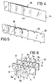
- Figure 4 shows a folded divider at a larger scale
- Figure 5 is a view similar to that of Figure 4, but with a folded divider provided with angular recesses on one of the longitudinal edges of the sheets and projections on the opposite edge
- Figure 6 is a perspective view of a folded divider with folded flaps on two opposite sides
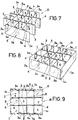
- Figure 7 is a view of an unfolded divider, provided on two opposite sides with two end sheets glued onto other folded flaps
- Figure 8 is a view similar to that of Figure 7, showing a divider provided with sheets on all four sides
- Figure 9 is a plan view of a divider of the version illustrated in Figure 7, situated inside a box.
- the divider for foldable cardboard boxes can be obtained by a manufacturing method which comprises a continuous displacement of an assembly or group of laminar cardboard strips -1- fed from as many bobbins (not shown) along a set path.
- the strips -1- are situated in different and separate planes, advantageously parallel to each other ( Figures 1 and 2), but laterally offset from each other ( Figure 2). All the strips, or at least all of them less some strips -1a- which are on the end sides of the group (as in the version illustrated in Figures 1 and 2), present either from the start, or from one point of their initial travel, some longitudinal grooves -2- which divide them into a number of longitudinal bands -3- and -4-.
- These grooves can be formed by discontinuous cuts or by continuous grooves which do not pass completely through the strips. In any case their function, as will be seen below, is to form fold-lines towards one side or the other. Beads or lines of glue -5- will be deposited on the bands -3-. Lines or beads of glue -5- will also be deposited on one of the strips -1a-. It is important to stress that the bands -3- which have lines of glue -5- deposited on them occupy positions offset from each other, following virtual lines A and B running diagonally with respect to the group of strips -1, 1a- ( Figure 2).
- the strips -1, 1a- converge progressively until, at a station of general reference -6- (comprising, for example, two adjacent rollers), they are overlapped on each other and glued under pressure. From this station -6-, the strips form a glued assembly -1b- which passes through a transverse cutting station -7- to provide pieces -9-, which in the version shown ( Figures 1 and 3) will be cut again into shorter pieces -10-, which will cosntitute the folded dividers.
- a station of general reference -6- comprising, for example, two adjacent rollers
- narrow flap-like bands -3a- are defined, with those on either side of the divider arranged in coplanar manner; these can then be glued directly to the sides of an unfolded box -12-, or to sheets -1a- of the divider itself, which shall in turn be juxtaposed onto the sides of the box -12- ( Figures 6 to 9), depending on whether the divider is fitted into the box using a mechanical or manual method, as outlined in greater detail below.
- straight cuts can be made to provide pieces -9- and -10- having straight longitudinal edges ( Figures 1, 3 and 4), or else broken or mixed outline cuts to form recesses -13- on one of the longitudinal edges (either the upper or lower), whose outline narrows progressively from the edge in question, as illustrated in Figure 5 of the drawings.
- these recesses -13- prevent the edge of the divider from striking against the edges of the bottle labels and causing them to come away.
- the above method allows fully finished dividers to be obtained in a continuous process, at a much higher production rate than with any of the known manufacturing methods and, therefore, at lower cost.
- the divider furthermore, independently of the manufacturing method used, has several advantages with respect to known versions.
- the divider In the first place, it can be incorporated into a box using a mechanized process: in this case the divider would be one like that shown in Figure 6 of the drawings, with the flaps -3a- glued onto the sides of the box.
- the divider object of the invention could be obtained from precut sheets instead of from continuous strips -1-.
Landscapes
- Engineering & Computer Science (AREA)
- Mechanical Engineering (AREA)
- Making Paper Articles (AREA)
- Cartons (AREA)
- Laminated Bodies (AREA)
Abstract
Description
- The present invention refers to a divider for foldable cardboard boxes and a method for manufacturing said divider, made up of an assembly of sheets of cardboard or other similar material, joined to each other in perpendicular positions so that they make up small cells or compartments for holding bottles or similar fragile objects, perfectly separated from each other.
- Known in the art are dividers for foldable cardboard boxes formed by assemblies of sheets or strips provided with complementary cuts for slotting in the intercrossed sheets. In these known embodiments only some of the sheets are glued to an internal side of the box; the other sheets are attached only to those which are glued to the box, but are not themselves attached to it.
- These dividers are configured in such a way that they are folded at the same time as the box, though the fact that not all the sheets are attached to the sides thereof provokes that the divider moves out of its correct position, which creates difficulties for folding and unfolding it.
- Another type of known divider is made up of a plurality of cardboard sheets provided with cutting lines and folding lines which serve to form flaps and strips in directions perpendicular to the flaps, those of one sheet being glued to those of the sheet immediately adjacent to it, so that they can be folded and unfolded at will, while the strips of the sheets situated at the ends of the assembly are glued to the sides of the box.
- Although these dividers have advantages over the traditional dividers formed by sheets or strips with cuts to slot them into intercrossed position, they are rather slow to manufacture and the process must be implemented using precut sheets which are later submitted to a process of die-cutting, folding and gluing. The known dividers are usually formed from ridged cardboard sheets whose rigidity prevents feed from bobbins, for which reason supply must be implemented as stated above, in the form of precut sheets, which means that the entire manufacturing process cannot be implemented continuously.
- The divider for cardboard boxes and a method for manufacturing the divider object of the present invention have been designed in order to solve the disadvantages outlined.
- The divider is made up of an assembly of strips or sheets of cardboard or similar material arranged in positions perpendicular to each other to form a plurality of compartments, at least some of which sheets or strips can be glued onto two opposite sides of the box. On the basis of this general embodiment, the divider is characterized in that it comprises an assembly of sheets provided with transverse fold lines, which make up bands folded in perpendicular directions with respect to bands juxtaposed and glued to the immediately adjacent sheets. The ends of the sheets which are situated on at least two opposite sides of the assembly are provided with flap-like bands folded transversally, those on each side being coplanar, glued to as many opposite sides of a box.
- In a possible embodiment, the folded flaps of at least two opposite sides of the assembly are glued to some sheets which are in turn juxtaposed on the corresponding sides of the box.
- Advantageously, one of the ends of each sheet situated on the opposite sides of the divider has one of its ends resting against the corresponding side of the box, in order to keep the divider unfolded.
- At least one of the longitudinal edges of the sheets is provided with recesses which narrow progressively from the aforesaid edges.
- The method for manufacturing dividers for foldable cardboard boxes comprises continuously feeding strips of flexible material which move along a path, said strips being provided with longitudinal grooves which will form fold lines in one or the other direction. These lines divide the strips into longitudinal bands of different widths, on at least some of which glue is placed. The strips are situated in different planes at the start of their travel, and as they move downstream they converge progressively until they are overlapped on each other and glued under pressure, each strip to those immediately adjacent, in positions which are laterally offset from each other, in order to form an assembly of strips overlapped and glued, which is then subjected to at least one transverse cutting operation to provide pieces which will constitute the folded dividers which will be glued to at least two opposite sides of a box.
- In a more specific embodiment, the glue is applied in bands, the bands of each sheet being offset with respect to those of the following sheets according to several imaginary lines in a diagonal direction with respect to the assembly of sheets.
- In a possible embodiment, the assembly of overlapped and glued strips is cut along straight lines.
- Provision has also been made for the assembly of overlapped and glued strips being cut along lines which form recesses and projections.
- For a better understanding of all that is set out in this specification, some drawings are attached which, solely by way of example, show a practical example of embodiment of the method for manufacturing the divider and of the divider assembly obtained using it.
- In these drawings, Figure 1 is a schematic perspective view showing the steps of the method; Figure 2 is a schematic cross section of the glued strips before they are overlapped; Figure 3 shows schematically the cutting into pieces of some sections of the precut glued strips, into shorter sections which constitute the folded dividers; Figure 4 shows a folded divider at a larger scale; Figure 5 is a view similar to that of Figure 4, but with a folded divider provided with angular recesses on one of the longitudinal edges of the sheets and projections on the opposite edge; Figure 6 is a perspective view of a folded divider with folded flaps on two opposite sides; Figure 7 is a view of an unfolded divider, provided on two opposite sides with two end sheets glued onto other folded flaps; Figure 8 is a view similar to that of Figure 7, showing a divider provided with sheets on all four sides, while Figure 9 is a plan view of a divider of the version illustrated in Figure 7, situated inside a box.
- The divider for foldable cardboard boxes can be obtained by a manufacturing method which comprises a continuous displacement of an assembly or group of laminar cardboard strips -1- fed from as many bobbins (not shown) along a set path. At the beginning of this path the strips -1- are situated in different and separate planes, advantageously parallel to each other (Figures 1 and 2), but laterally offset from each other (Figure 2). All the strips, or at least all of them less some strips -1a- which are on the end sides of the group (as in the version illustrated in Figures 1 and 2), present either from the start, or from one point of their initial travel, some longitudinal grooves -2- which divide them into a number of longitudinal bands -3- and -4-. These grooves can be formed by discontinuous cuts or by continuous grooves which do not pass completely through the strips. In any case their function, as will be seen below, is to form fold-lines towards one side or the other. Beads or lines of glue -5- will be deposited on the bands -3-. Lines or beads of glue -5- will also be deposited on one of the strips -1a-. It is important to stress that the bands -3- which have lines of glue -5- deposited on them occupy positions offset from each other, following virtual lines A and B running diagonally with respect to the group of strips -1, 1a- (Figure 2).
- On their downstream travel along the path, the strips -1, 1a- converge progressively until, at a station of general reference -6- (comprising, for example, two adjacent rollers), they are overlapped on each other and glued under pressure. From this station -6-, the strips form a glued assembly -1b- which passes through a transverse cutting station -7- to provide pieces -9-, which in the version shown (Figures 1 and 3) will be cut again into shorter pieces -10-, which will cosntitute the folded dividers.
- By virtue of the position of the glued bands -3-, upon unfolding of the piece -10- a divider -11- is formed, in which the strips -1- are linked to each other through the unglued sections -4-, arranged at right angles to the glued sections -3-, with the special feature that the sections -3- of each strip -1- are folded in opposite directions along the fold-lines formed by the grooves -2-. Compartments "C" are defined between the sections -4- and the sheets -1-, to hold bottles or other articles.
- It should be noted that at the ends of the strips situated on two or four sides of the divider -11-, narrow flap-like bands -3a- are defined, with those on either side of the divider arranged in coplanar manner; these can then be glued directly to the sides of an unfolded box -12-, or to sheets -1a- of the divider itself, which shall in turn be juxtaposed onto the sides of the box -12- (Figures 6 to 9), depending on whether the divider is fitted into the box using a mechanical or manual method, as outlined in greater detail below.
- At the cutting station -7- and other stations down the line but not shown, straight cuts can be made to provide pieces -9- and -10- having straight longitudinal edges (Figures 1, 3 and 4), or else broken or mixed outline cuts to form recesses -13- on one of the longitudinal edges (either the upper or lower), whose outline narrows progressively from the edge in question, as illustrated in Figure 5 of the drawings. When the divider is fitted between the bottles previously situated in a box, or when bottles are placed into the divider fitted into the box, these recesses -13- prevent the edge of the divider from striking against the edges of the bottle labels and causing them to come away.
- As can be deduced from all that has been described and from observation of the drawing, the above method allows fully finished dividers to be obtained in a continuous process, at a much higher production rate than with any of the known manufacturing methods and, therefore, at lower cost.
- With this procedure the dividers are obtained from continuous laminar cardboard strips, of lower cost than the ridged cardboard sheets which have been used to manufacture known dividers.
- The divider, furthermore, independently of the manufacturing method used, has several advantages with respect to known versions. In the first place, it can be incorporated into a box using a mechanized process: in this case the divider would be one like that shown in Figure 6 of the drawings, with the flaps -3a- glued onto the sides of the box. It is also possible to obtain a divider with sheets -1a- (Figures 7 and 8), for manual placement inside the box -12-. In this case, at least one of the ends -1c- of the sheets -1a- rests on the sides of the box -12- to prevent it being folded accidentally. Between the end -1c- and the immediately adjacent section -4- there is a space equivalent to that existing between two parallel and immediately adjacent sections -4- of the divider, in order to form compartments "C" (Figure 9).
- It should be noted, finally, that the divider object of the invention could be obtained from precut sheets instead of from continuous strips -1-.
- Independent of the object of the invention shall be the number of strips of cardboard or similar material from which the dividers are obtained, as well as their dimensions and, consequently, the number and dimensions of the sheets or strips formed by the manufactured dividers. The particular mechanisms used to carry out the different steps of the method shall also be optional.
Claims (8)
- A divider for foldable cardboard boxes, made up of an assembly of strips or sheets of cardboard or similar material arranged in positions perpendicular to each other to form a plurality of compartments "C", at least some of said sheets or strips being optionally glued onto two opposite sides of the box, characterized in that it comprises an assembly of sheets (1) provided with transverse fold lines (2), which define bands (4) folded at right angles with respect to bands (3) juxtaposed and glued to the immediately adjacent sheets, the ends of the sheets which are situated on at least two opposite sides of the assembly presenting flap-like folded bands (3a), those on each side being coplanar, glued to as many opposite sides of a box (12).
- A divider as claimed in claim 1, characterized in that folded flaps (3a) of at least two opposite sides of the assembly of sheets (1) are glued to some sheets (1a) which are in turn juxtaposed on the corresponding sides of the box.
- A divider as claimed in claims 1 and 2, characterized in that one of the edges (1c) of the sheets situated on at least the two opposite sides of the divider rests against opposite sides of the box (12), in order to keep the divider immobile inside the box.
- A divider as claimed in claim 1 and either of claims 2 and 3, characterized in that at least one of the longitudinal edges of the sheets is provided with recesses (13) which narrow progressively from the aforesaid edges.
- A method for manufacturing a divider for foldable cardboard boxes as claimed in claim 1 and any of claims 2 to 4, characterized in that it comprises continuously feeding strips (1, 1a) of flexible material which move along a path, said strips being provided with longitudinal grooves (2) which will define fold lines in one or the other direction and which divide the strip into longitudinal bands (3, 4) of different widths, on at least some of which glue (5) is placed; the bands are situated in different planes at the start of their travel, and as they move on downstream they converge progressively until they are overlapped on each other and glued under pressure, each strip to those immediately adjacent, in positions which are laterally offset, to form an assembly (1b) of strips overlapped and glued, which is then subjected to at least one transverse cutting (7) operation to provide pieces (9, 10) which will constitute the folded dividers which will be unfolded and glued to at least two opposite sides of a box (12).
- A method for manufacturing a divider for foldable cardboard boxes as claimed in claims 1 and 5, characterized in that the glue (5) is applied in bands (3, 3a), the bands of each sheet being offset with respect to those of the following sheets according to several imaginary lines (A, B) in a diagonal direction with respect to the assembly of sheets.
- A method for manufacturing a divider for foldable cardboard boxes as claimed in claims 1 and 5, characterized in that the assembly of overlapped and glued strips is cut along straight lines.
- A method for manufacturing a divider for foldable cardboard boxes as claimed in claims 1 and 4, characterized in that the assembly of overlapped and glued strips is cut along lines which form recesses (13) and projections.
Applications Claiming Priority (2)
| Application Number | Priority Date | Filing Date | Title |
|---|---|---|---|
| ES09400980A ES2111437B1 (en) | 1994-05-10 | 1994-05-10 | SEPARATOR FOR FOLDING CARDBOARD BOXES AND MANUFACTURING PROCEDURE FOR SUCH SEPARATOR. |
| ES9400980 | 1994-05-10 |
Publications (2)
| Publication Number | Publication Date |
|---|---|
| EP0681963A1 true EP0681963A1 (en) | 1995-11-15 |
| EP0681963B1 EP0681963B1 (en) | 1999-05-19 |
Family
ID=8286158
Family Applications (1)
| Application Number | Title | Priority Date | Filing Date |
|---|---|---|---|
| EP95500069A Expired - Lifetime EP0681963B1 (en) | 1994-05-10 | 1995-05-05 | Divider for foldable cardboard boxes and a method for manufacturing said divider |
Country Status (10)
| Country | Link |
|---|---|
| US (1) | US5601521A (en) |
| EP (1) | EP0681963B1 (en) |
| JP (1) | JP3088634B2 (en) |
| CN (1) | CN1045073C (en) |
| AT (1) | ATE180233T1 (en) |
| AU (1) | AU685915B2 (en) |
| DE (1) | DE69509701T2 (en) |
| ES (1) | ES2111437B1 (en) |
| RU (1) | RU2118278C1 (en) |
| ZA (1) | ZA953784B (en) |
Cited By (5)
| Publication number | Priority date | Publication date | Assignee | Title |
|---|---|---|---|---|
| WO1998006632A1 (en) * | 1996-08-09 | 1998-02-19 | Videcart, S.A. | Separator for cardboard boxes |
| EP1498358A1 (en) * | 2003-05-31 | 2005-01-19 | Conteyor Multibag Systems N.V. | Method of manufacture for a flexible container having partitions |
| US8991685B2 (en) | 2011-11-09 | 2015-03-31 | Rts Packaging Llc | Partition |
| EP3831592A1 (en) * | 2019-12-06 | 2021-06-09 | Technische Universität Dresden | Method for manufacturing a cell structure, cell structure and its use |
| WO2021173603A1 (en) * | 2020-02-24 | 2021-09-02 | Amgen Inc. | Containers and systems for use during external sterilization of drug delivery devices |
Families Citing this family (25)
| Publication number | Priority date | Publication date | Assignee | Title |
|---|---|---|---|---|
| US6569072B1 (en) * | 1999-12-08 | 2003-05-27 | Kay Packaging Company, Inc. | Partition manufacturing method and apparatus |
| AU2002361660A1 (en) * | 2001-12-14 | 2003-06-30 | Graphic Packaging Corporation | Packages, blanks for making packages and associated methods and apparatus |
| US20060283927A1 (en) * | 2002-12-13 | 2006-12-21 | Walsh Joseph C | Packages, blank for making packages and associated methods |
| US7658318B2 (en) * | 2002-12-13 | 2010-02-09 | Graphic Packaging International, Inc. | Packages, blanks for making packages and associated methods |
| WO2006133394A2 (en) | 2005-06-08 | 2006-12-14 | Graphic Packaging International, Inc. | Packages, blanks for making packages and associated methods |
| US8196805B2 (en) | 2006-05-18 | 2012-06-12 | Graphic Packaging International, Inc. | Cartons with liquid-tight receptacles |
| CA2678056C (en) * | 2007-02-23 | 2015-02-03 | Graphic Packaging International, Inc. | Reinforced carton and methods of making carton blanks |
| PL2164759T3 (en) * | 2007-05-15 | 2012-11-30 | Itb Packaging | Cellular container |
| US8241450B2 (en) * | 2007-12-17 | 2012-08-14 | Nike, Inc. | Method for inflating a fluid-filled chamber |
| USD613164S1 (en) * | 2009-03-10 | 2010-04-06 | Yeong-Hee Lee | Cell partition for package |
| WO2011060411A2 (en) | 2009-11-16 | 2011-05-19 | Graphic Packaging International, Inc. | Expandable carton |
| JP5249913B2 (en) * | 2009-12-04 | 2013-07-31 | 株式会社クラウン・パッケージ | Manufacturing method of assembly and assembly |
| US8997442B2 (en) * | 2011-02-04 | 2015-04-07 | C. Raker & Sons, Inc. | Shipping system for plants or other items |
| CN102095061B (en) * | 2011-02-28 | 2013-03-13 | 深圳市豪鹏科技有限公司 | Knife card inserting clamp |
| US8720770B2 (en) | 2011-03-01 | 2014-05-13 | The Golden Box, Inc. | Box partition set |
| US9669966B2 (en) * | 2012-11-08 | 2017-06-06 | E. & J. Gallo Winery | Method and apparatus for wine bottle packaging and display |
| US10124947B2 (en) | 2014-06-23 | 2018-11-13 | Graphic Packaging International, Llc | Carton with dispensing features |
| US10773856B2 (en) * | 2016-02-09 | 2020-09-15 | Itb Packaging Llc | Container assembly having a cell assembly therein and methods for forming |
| ES2665814B1 (en) * | 2016-10-27 | 2019-02-05 | Procarton S A | SHEET FOR SEPARATORS OF CARTON BOXES AND SEPARATOR OBTAINED. |
| MX393550B (en) | 2016-11-14 | 2025-03-24 | Graphic Packaging Int Llc | RECONFIGURABLE CARDBOARD BOX AND PACKAGING. |
| CN108001781A (en) * | 2017-12-28 | 2018-05-08 | 上海聚特展示用品有限公司 | A kind of display heap case with water-proof function |
| CN108582891B (en) * | 2018-04-23 | 2019-08-27 | 上海义速自动化设备有限公司 | A grid carton forming machine |
| CA3020033A1 (en) | 2018-10-05 | 2020-04-05 | Wine Warden Ltd | Refrigerated gel pack divider for keeping beverage bottles cool during beverage box transport |
| CN111056115B (en) * | 2019-10-29 | 2024-08-13 | 杭州秉信环保包装有限公司 | Single cut-off piece knife clamp structure |
| CN112389028B (en) * | 2020-10-31 | 2024-04-26 | 乐陵帝荣包装机械设备有限公司 | Paper turns over a processing apparatus |
Citations (4)
| Publication number | Priority date | Publication date | Assignee | Title |
|---|---|---|---|---|
| US2549801A (en) * | 1947-10-06 | 1951-04-24 | Gaylord Container Corp | Collapsible container partition and liner unit |
| US3011672A (en) * | 1958-05-28 | 1961-12-05 | Crown Zellerbach Canada Ltd | Glued cell forming divider |
| FR1395153A (en) * | 1964-04-20 | 1965-04-09 | Reed Paper Group Ltd | Improvement in partitioning elements, in particular for packaging fragile items |
| FR2687384A1 (en) * | 1992-02-17 | 1993-08-20 | Socar | Package made of corrugated cardboard, fitted with a cross-piece defining parallel housings for objects such as bottles |
Family Cites Families (9)
| Publication number | Priority date | Publication date | Assignee | Title |
|---|---|---|---|---|
| US672A (en) * | 1838-04-04 | Plaiting-machine for covering whips | ||
| NL102542C (en) * | 1958-02-25 | 1900-01-01 | ||
| US3493450A (en) * | 1965-10-23 | 1970-02-03 | Honeycomb Co Of America Inc | Honeycomb core machine and method |
| US3518251A (en) * | 1967-06-07 | 1970-06-30 | Geigy Ag J R | Certain aminoalkylamino substituted azacycloalkenes |
| US3741840A (en) * | 1969-11-14 | 1973-06-26 | J Booth | Method for producing continuous compressed honeycomb |
| US3713954A (en) * | 1970-08-03 | 1973-01-30 | Union Camp Corp | Honeycomb making machine |
| CA1078296A (en) * | 1975-02-19 | 1980-05-27 | Robert C. Geschwender | Apparatus for and method of forming honeycomb material |
| US4829747A (en) * | 1986-09-23 | 1989-05-16 | Wayne Automation Corp. | Method for opening and inserting multi-cell partitions |
| DE3820718C1 (en) * | 1988-06-18 | 1989-05-11 | Hans Aesch Ch Schmidlin |
-
1994
- 1994-05-10 ES ES09400980A patent/ES2111437B1/en not_active Expired - Fee Related
-
1995
- 1995-05-05 DE DE69509701T patent/DE69509701T2/en not_active Expired - Fee Related
- 1995-05-05 AT AT95500069T patent/ATE180233T1/en not_active IP Right Cessation
- 1995-05-05 EP EP95500069A patent/EP0681963B1/en not_active Expired - Lifetime
- 1995-05-06 RU RU95107158A patent/RU2118278C1/en active
- 1995-05-09 AU AU17968/95A patent/AU685915B2/en not_active Ceased
- 1995-05-09 US US08/437,467 patent/US5601521A/en not_active Expired - Lifetime
- 1995-05-10 JP JP07111979A patent/JP3088634B2/en not_active Expired - Fee Related
- 1995-05-10 CN CN95105707A patent/CN1045073C/en not_active Expired - Fee Related
- 1995-05-10 ZA ZA953784A patent/ZA953784B/en unknown
Patent Citations (4)
| Publication number | Priority date | Publication date | Assignee | Title |
|---|---|---|---|---|
| US2549801A (en) * | 1947-10-06 | 1951-04-24 | Gaylord Container Corp | Collapsible container partition and liner unit |
| US3011672A (en) * | 1958-05-28 | 1961-12-05 | Crown Zellerbach Canada Ltd | Glued cell forming divider |
| FR1395153A (en) * | 1964-04-20 | 1965-04-09 | Reed Paper Group Ltd | Improvement in partitioning elements, in particular for packaging fragile items |
| FR2687384A1 (en) * | 1992-02-17 | 1993-08-20 | Socar | Package made of corrugated cardboard, fitted with a cross-piece defining parallel housings for objects such as bottles |
Cited By (7)
| Publication number | Priority date | Publication date | Assignee | Title |
|---|---|---|---|---|
| WO1998006632A1 (en) * | 1996-08-09 | 1998-02-19 | Videcart, S.A. | Separator for cardboard boxes |
| ES2133070A1 (en) * | 1996-08-09 | 1999-08-16 | Paper Sa | Separator for cardboard boxes |
| EP1498358A1 (en) * | 2003-05-31 | 2005-01-19 | Conteyor Multibag Systems N.V. | Method of manufacture for a flexible container having partitions |
| US8991685B2 (en) | 2011-11-09 | 2015-03-31 | Rts Packaging Llc | Partition |
| EP3831592A1 (en) * | 2019-12-06 | 2021-06-09 | Technische Universität Dresden | Method for manufacturing a cell structure, cell structure and its use |
| WO2021173603A1 (en) * | 2020-02-24 | 2021-09-02 | Amgen Inc. | Containers and systems for use during external sterilization of drug delivery devices |
| US12240652B2 (en) | 2020-02-24 | 2025-03-04 | Amgen Inc. | Containers and systems for use during external sterilization of drug delivery devices |
Also Published As
| Publication number | Publication date |
|---|---|
| JPH0840431A (en) | 1996-02-13 |
| US5601521A (en) | 1997-02-11 |
| AU685915B2 (en) | 1998-01-29 |
| RU2118278C1 (en) | 1998-08-27 |
| CN1045073C (en) | 1999-09-15 |
| EP0681963B1 (en) | 1999-05-19 |
| ATE180233T1 (en) | 1999-06-15 |
| ES2111437R (en) | 1998-04-16 |
| DE69509701T2 (en) | 1999-12-23 |
| RU95107158A (en) | 1997-03-20 |
| CN1112894A (en) | 1995-12-06 |
| ES2111437B1 (en) | 1998-12-01 |
| DE69509701D1 (en) | 1999-06-24 |
| AU1796895A (en) | 1995-11-16 |
| ZA953784B (en) | 1996-01-16 |
| ES2111437A2 (en) | 1998-03-01 |
| JP3088634B2 (en) | 2000-09-18 |
Similar Documents
| Publication | Publication Date | Title |
|---|---|---|
| US5601521A (en) | Method for manufacturing a divider for a cardboard box | |
| US4623072A (en) | Corrugated container with foldable flaps | |
| US5458374A (en) | Universal non-jamming multi-ply multi-fold outsert with compact peripheral edges (and related method) | |
| EP0608909B1 (en) | Process and device for making packages made from sheet material | |
| US6007469A (en) | Method for forming a honeycomb corner protector with self-locking panels | |
| US4349973A (en) | Pop-ups and methods of making | |
| US4282999A (en) | H-divider containers | |
| US5509987A (en) | Method for producing a bonded multiweb product | |
| JPS59171693A (en) | Print consisting of plurality of bent sheet and manufacture thereof | |
| US4108352A (en) | Continuous business forms assembly with anti-tenting means | |
| US4621764A (en) | Partition assembly with interlocks having glued tabs | |
| DE3602210C2 (en) | ||
| US4913694A (en) | Method for manufacturing a picture and/or text changing slide | |
| US4221161A (en) | Method of forming a double pocket envelope | |
| US1997718A (en) | Folding box and method of making the same | |
| US5088220A (en) | Pop-out slide | |
| GB2116904A (en) | Packaging partitions | |
| US5009362A (en) | Quick-assembled folding carton with reinforced bottom that locks in position | |
| EP2399839A1 (en) | Tobacco pouch with closure tab and method for producing same | |
| JPH031990A (en) | Mailer product and manufacture thereof | |
| EP0495742A1 (en) | Separator for foldable cardboard boxes | |
| US3344719A (en) | Method and apparatus for making envelopes | |
| US5516039A (en) | Carton blank | |
| EP0323079B1 (en) | Apparatus for interlocking a pair of panels | |
| FR2480178A1 (en) | PROCESS FOR PRODUCING A PACKAGING, IN PARTICULAR FOR EGGS |
Legal Events
| Date | Code | Title | Description |
|---|---|---|---|
| PUAI | Public reference made under article 153(3) epc to a published international application that has entered the european phase |
Free format text: ORIGINAL CODE: 0009012 |
|
| AK | Designated contracting states |
Kind code of ref document: A1 Designated state(s): AT BE CH DE FR GB GR IE IT LI NL PT |
|
| 17P | Request for examination filed |
Effective date: 19960509 |
|
| 17Q | First examination report despatched |
Effective date: 19970321 |
|
| GRAG | Despatch of communication of intention to grant |
Free format text: ORIGINAL CODE: EPIDOS AGRA |
|
| GRAG | Despatch of communication of intention to grant |
Free format text: ORIGINAL CODE: EPIDOS AGRA |
|
| GRAH | Despatch of communication of intention to grant a patent |
Free format text: ORIGINAL CODE: EPIDOS IGRA |
|
| GRAH | Despatch of communication of intention to grant a patent |
Free format text: ORIGINAL CODE: EPIDOS IGRA |
|
| GRAA | (expected) grant |
Free format text: ORIGINAL CODE: 0009210 |
|
| AK | Designated contracting states |
Kind code of ref document: B1 Designated state(s): AT BE CH DE FR GB GR IE IT LI NL PT |
|
| PG25 | Lapsed in a contracting state [announced via postgrant information from national office to epo] |
Ref country code: NL Free format text: LAPSE BECAUSE OF FAILURE TO SUBMIT A TRANSLATION OF THE DESCRIPTION OR TO PAY THE FEE WITHIN THE PRESCRIBED TIME-LIMIT Effective date: 19990519 Ref country code: LI Free format text: LAPSE BECAUSE OF FAILURE TO SUBMIT A TRANSLATION OF THE DESCRIPTION OR TO PAY THE FEE WITHIN THE PRESCRIBED TIME-LIMIT Effective date: 19990519 Ref country code: GR Free format text: LAPSE BECAUSE OF NON-PAYMENT OF DUE FEES Effective date: 19990519 Ref country code: CH Free format text: LAPSE BECAUSE OF FAILURE TO SUBMIT A TRANSLATION OF THE DESCRIPTION OR TO PAY THE FEE WITHIN THE PRESCRIBED TIME-LIMIT Effective date: 19990519 Ref country code: BE Free format text: LAPSE BECAUSE OF FAILURE TO SUBMIT A TRANSLATION OF THE DESCRIPTION OR TO PAY THE FEE WITHIN THE PRESCRIBED TIME-LIMIT Effective date: 19990519 Ref country code: AT Free format text: LAPSE BECAUSE OF FAILURE TO SUBMIT A TRANSLATION OF THE DESCRIPTION OR TO PAY THE FEE WITHIN THE PRESCRIBED TIME-LIMIT Effective date: 19990519 |
|
| REF | Corresponds to: |
Ref document number: 180233 Country of ref document: AT Date of ref document: 19990615 Kind code of ref document: T |
|
| REG | Reference to a national code |
Ref country code: CH Ref legal event code: EP |
|
| REG | Reference to a national code |
Ref country code: IE Ref legal event code: FG4D |
|
| REF | Corresponds to: |
Ref document number: 69509701 Country of ref document: DE Date of ref document: 19990624 |
|
| ITF | It: translation for a ep patent filed | ||
| ET | Fr: translation filed | ||
| REG | Reference to a national code |
Ref country code: PT Ref legal event code: SC4A Free format text: AVAILABILITY OF NATIONAL TRANSLATION Effective date: 19990806 Ref country code: CH Ref legal event code: PL |
|
| PLBE | No opposition filed within time limit |
Free format text: ORIGINAL CODE: 0009261 |
|
| STAA | Information on the status of an ep patent application or granted ep patent |
Free format text: STATUS: NO OPPOSITION FILED WITHIN TIME LIMIT |
|
| 26N | No opposition filed | ||
| REG | Reference to a national code |
Ref country code: GB Ref legal event code: IF02 |
|
| PGFP | Annual fee paid to national office [announced via postgrant information from national office to epo] |
Ref country code: IE Payment date: 20040512 Year of fee payment: 10 Ref country code: GB Payment date: 20040512 Year of fee payment: 10 |
|
| PGFP | Annual fee paid to national office [announced via postgrant information from national office to epo] |
Ref country code: FR Payment date: 20040528 Year of fee payment: 10 |
|
| PG25 | Lapsed in a contracting state [announced via postgrant information from national office to epo] |
Ref country code: IT Free format text: LAPSE BECAUSE OF NON-PAYMENT OF DUE FEES;WARNING: LAPSES OF ITALIAN PATENTS WITH EFFECTIVE DATE BEFORE 2007 MAY HAVE OCCURRED AT ANY TIME BEFORE 2007. THE CORRECT EFFECTIVE DATE MAY BE DIFFERENT FROM THE ONE RECORDED. Effective date: 20050505 Ref country code: IE Free format text: LAPSE BECAUSE OF NON-PAYMENT OF DUE FEES Effective date: 20050505 Ref country code: GB Free format text: LAPSE BECAUSE OF NON-PAYMENT OF DUE FEES Effective date: 20050505 |
|
| GBPC | Gb: european patent ceased through non-payment of renewal fee |
Effective date: 20050505 |
|
| PG25 | Lapsed in a contracting state [announced via postgrant information from national office to epo] |
Ref country code: FR Free format text: LAPSE BECAUSE OF NON-PAYMENT OF DUE FEES Effective date: 20060131 |
|
| REG | Reference to a national code |
Ref country code: IE Ref legal event code: MM4A |
|
| REG | Reference to a national code |
Ref country code: FR Ref legal event code: ST Effective date: 20060131 |
|
| PGFP | Annual fee paid to national office [announced via postgrant information from national office to epo] |
Ref country code: PT Payment date: 20090424 Year of fee payment: 15 Ref country code: DE Payment date: 20090429 Year of fee payment: 15 |
|
| REG | Reference to a national code |
Ref country code: PT Ref legal event code: MM4A Free format text: LAPSE DUE TO NON-PAYMENT OF FEES Effective date: 20101105 |
|
| PG25 | Lapsed in a contracting state [announced via postgrant information from national office to epo] |
Ref country code: PT Free format text: LAPSE BECAUSE OF NON-PAYMENT OF DUE FEES Effective date: 20101105 |
|
| PG25 | Lapsed in a contracting state [announced via postgrant information from national office to epo] |
Ref country code: DE Free format text: LAPSE BECAUSE OF NON-PAYMENT OF DUE FEES Effective date: 20101201 |