EP0681453B1 - Method and device to sense breathing - Google Patents
Method and device to sense breathing Download PDFInfo
- Publication number
- EP0681453B1 EP0681453B1 EP94905297A EP94905297A EP0681453B1 EP 0681453 B1 EP0681453 B1 EP 0681453B1 EP 94905297 A EP94905297 A EP 94905297A EP 94905297 A EP94905297 A EP 94905297A EP 0681453 B1 EP0681453 B1 EP 0681453B1
- Authority
- EP
- European Patent Office
- Prior art keywords
- breathing
- sensor
- signal
- optical
- optical signal
- Prior art date
- Legal status (The legal status is an assumption and is not a legal conclusion. Google has not performed a legal analysis and makes no representation as to the accuracy of the status listed.)
- Expired - Lifetime
Links
- 230000029058 respiratory gaseous exchange Effects 0.000 title claims abstract description 71
- 238000000034 method Methods 0.000 title claims abstract description 9
- 230000003287 optical effect Effects 0.000 claims abstract description 42
- 239000004020 conductor Substances 0.000 claims description 25
- 230000008878 coupling Effects 0.000 claims 2
- 238000010168 coupling process Methods 0.000 claims 2
- 238000005859 coupling reaction Methods 0.000 claims 2
- 239000000835 fiber Substances 0.000 abstract description 26
- 239000013307 optical fiber Substances 0.000 abstract description 13
- 239000003595 mist Substances 0.000 abstract description 5
- 230000001419 dependent effect Effects 0.000 abstract 2
- 239000003570 air Substances 0.000 description 11
- QVGXLLKOCUKJST-UHFFFAOYSA-N atomic oxygen Chemical compound [O] QVGXLLKOCUKJST-UHFFFAOYSA-N 0.000 description 4
- 239000001301 oxygen Substances 0.000 description 4
- 229910052760 oxygen Inorganic materials 0.000 description 4
- 230000005855 radiation Effects 0.000 description 3
- XLYOFNOQVPJJNP-UHFFFAOYSA-N water Substances O XLYOFNOQVPJJNP-UHFFFAOYSA-N 0.000 description 3
- 230000005494 condensation Effects 0.000 description 2
- 238000009833 condensation Methods 0.000 description 2
- 229920003023 plastic Polymers 0.000 description 2
- 239000012080 ambient air Substances 0.000 description 1
- 230000005540 biological transmission Effects 0.000 description 1
- 230000035565 breathing frequency Effects 0.000 description 1
- 238000006243 chemical reaction Methods 0.000 description 1
- 238000005253 cladding Methods 0.000 description 1
- 238000007796 conventional method Methods 0.000 description 1
- 238000001514 detection method Methods 0.000 description 1
- 238000010586 diagram Methods 0.000 description 1
- 238000002474 experimental method Methods 0.000 description 1
- 230000005669 field effect Effects 0.000 description 1
- 239000007789 gas Substances 0.000 description 1
- 239000000463 material Substances 0.000 description 1
- 239000013308 plastic optical fiber Substances 0.000 description 1
- 229920000573 polyethylene Polymers 0.000 description 1
- 229920006395 saturated elastomer Polymers 0.000 description 1
- 230000001960 triggered effect Effects 0.000 description 1
Images



Classifications
-
- A—HUMAN NECESSITIES
- A61—MEDICAL OR VETERINARY SCIENCE; HYGIENE
- A61B—DIAGNOSIS; SURGERY; IDENTIFICATION
- A61B5/00—Measuring for diagnostic purposes; Identification of persons
- A61B5/08—Measuring devices for evaluating the respiratory organs
- A61B5/0816—Measuring devices for examining respiratory frequency
-
- A—HUMAN NECESSITIES
- A61—MEDICAL OR VETERINARY SCIENCE; HYGIENE
- A61B—DIAGNOSIS; SURGERY; IDENTIFICATION
- A61B5/00—Measuring for diagnostic purposes; Identification of persons
- A61B5/08—Measuring devices for evaluating the respiratory organs
- A61B5/087—Measuring breath flow
Definitions
- the present invention refers to a method and device to sense breathing.
- the EP-A-0 309 666 discloses a device to sense breathing which includes means for emitting an optical signal, a breathing sensor with a sensor surface and means to sense changes in the optical signal from the sensor as a measure of breathing.
- the changes of the optical signal are related to selected light wavelengths to sense a special gas concentration in the breathing air flow.
- the WO-A-9 218 848 describes an optical moisture sensor including an infrared emitter and a sensor receiving the infrared signal reflected by internal reflexion on a windscreen in order to measure the presence of moisture on the outside surface of the windscreen.
- the moisture sensor is optically coupled to the inside surface of the windscreen.
- An object of the present invention is to achieve a method and a device to sense the breathing and a breathing sensor of a new, simple and reliable type which can be utilized in a flexible way in the connections there is desire to sense the breathing.
- An object is also to achieve breathing sensors which easily can be carried by a patient and which do not need to incorporate electric cabies at the proximity of the body.
- An additional object is to achieve breathing sensors which are easy to keep clean and when needed sterile and which are so cheap that if desired they can be utilized as disposable products. Further objects and purposes appear in greater detail in connection with the following specification.
- the method and the device to sense the breathing according to the present invention is based on the fact that the humidity of the breating air varies strongly between in- and exhalation. At inhalation the relative humidity in the breathing air flow at the nose or the mouth approximately is the same as that of the ambient air, i.e. frequently far below 100 % while at exhalation it is basically saturated with water vapour, i.e. 100 % relative humidity.
- the condensation course can be studied in the following way.
- Light or other electromagnetic beam is guided into the optical fibre which beam in turn can be guided by means of an optical fibre from a source which can be a laser, laser diode, light emitting diode or some bulb.
- the optical beam that reaches at the far end of the fibre partly will be reflected and partly leak out. If the end of the fibre becomes coated by mist this relation will be changed so that a smaller part of the ray will be reflected back when the fibre is moist than when it is dry.
- the reason for this is that the small drops of water constituting the mist form small lenses which let out radiation in more angles than what is the case of the dry fibre.
- the breathing then can be sensed as intensity variations of the reflected light by any appropriate method which is exemplified below.
- the intensity variations of the beam that is transmitted in order to sense the breathing from this variation.
- This can for example be carried out by means of a photo detector or another fibre end which captures a part of the transmitted radiation at the proximity of the first end of the fibre.
- the principle according to the present invention in another way.
- a loop of an optical fibre can be utilized, where the sensor surface is constituted by a window of arbitrary form which lets out a part of the radiation guided in the fibre but guides the remainder further to the other end of the fibre.
- the moisture on the window influences the intensity of the beam that is emitted through the window and thereby also the beam that is guided further in the fibre.
- the principle according to the invention without any optical conductor or fibre being used. If a wholly or partly reflective or transmitting element is placed in the breathing stream and exposed to an optical signal the transmitted or the reflected signal can be sensed and the breathing be determined from its variations.
- the optical signal can be directed directly against the reflective or transmitting element and the sensor likewise, or else either the source of the optical signal or the sensor or both may include reflective or transmitting elements which constitute a sensor surface.
- a laser drive circuit 1 is coupled to a laser diode 2, the optical signal of which is conducted via a first optical conductor 4, a fibre coupler 3 and a second optical conductor 5 to the proximity of a breathing path of a person 7 who constitutes a measuring object.
- the fibre coupler 3 is such that the optical signal from the conductor 4 in the main is conducted further to the conductor 5 while the output signal on the third optical conductor 6 primarily originates from the optical signal which is conducted into the fibre coupler 3 from the other optical conductor 5 and which in the present case originates from the part of the signal from the laser diode 2 that is reflected by the end of the second optical fibre 5 where the very sensor surface is situated.
- the fibre coupler 3 can consist of the first (4) and the third (6) fibre being joined edge to edge with the second fibre 5, the diameter of which is twice the size of the rest.
- the electric output signal which is generated by the light falling on the photo detector consists of two parts.
- a DC-level which only depends on the characteristics of the beam source, of the fibre and of the photo detector and a voltage variation superimposed on this which depends on how large a portion of the incident beam which, due to the mist on the sensor surface by the fibre end, is coupled out from the fibre at the measuring object.
- the superimposed voltage level has the character of a sinusoidal wave.
- the breathing depending output signal from the photo detector 8 can be used and processed in various ways. What is illustrated in Figure 1 is a detector circuit 9, which is intended to convert the signal of the photo detector to square wave pulses in time to the breathing. These are converted in the time-to-frequency converter 10 to the breathing frequency which is shown on a display 11.
- Figure 2 shows a preferred embodiment of a breathing sensor according to the invention.
- the end surface 51 of the optical conductor 5 forms a sensor surface that normally lets out a part of the supplied optical signal and reflects a part, whereby the relationship between transmission and reflection is influenced by the condensation rate on the sensor surface 51 initiated by the air flow 71 of the breathing.
- the signal 52 in the optical conductor 5 consequently includes a supplied signal and a reflected signal.
- the end of the optical conductor 5 with the sensor surface 51 is surrounded by mainly a tubular holder 20 intended to keep the conductor 5 and the sensor surface 51 on site in the breathing air flow in for example a nostril.
- the optical conductor 5 can be constituted by a commercially available optical fibre of plastic.
- the sensor surface 51 preferably should lie mainly in parallel to the air flow.
- a variant of the breathing sensor appears in Figure 3.
- the sensor surface 53 here instead constitutes a portion of an optical conductor on which the cladding layer of the conductor has been removed, and the conductor here instead constitutes a loop so that part of the beam supplied which does not leave the conductor at the sensor surface 53 is conducted further to a receiver.
- no fibre coupler 3 or the like is required but one end 4 may receive the supplied beam 41 while the other end 6 emits an output signal 61 which can pass directly to a photo detector 8.
- Figure 5 and 6 shows two alternate designs of the breathing sensors operating according to the same principle as that of Figure 2. Both are built up from essentially tube shaped holders 20a and 20b respectively with a substantially ball shaped end intended to be inserted into the nose and possibly one or more external grooves, and contains a main channel 21 for the breathing stream.
- the optical fibre 5 is fixed coaxially with the main channel 21 so that the sensor surface 51 is directed towards the breathing stream.
- a number of smaller holes 22 are arranged about the attachment for the optical fibre 5, so that the breathing stream can flow through the main channel 21, past the sensor surface 51 and through the holes 22.
- the main channel 21 has a diameter reaching to about 8 mm which ends in five holes 22 of about 3,5 mm in diameter.
- a groove 23 for an oxygen catheter may be provided in the holder 20a, and an oxygen catheter may be guided together with the optical fibre 5 from the patient.
- Holder elements 25 or 25a according to Figure 5b which have openings and channels adapted to retain the optical fibre and the oxygen catheter respectively, can be utilized for this purpose.
- the main channel 21 is passing through and the optical fibre 5 is provided radially in the main channel so that the breathing stream sweeps past and mainly parallel to the sensor surface 51. It is also possible to provide the fibre 5 and the sensor surface 51 in other angles with respect to the breathing stream than those appearing in the embodiments shown.
- the holders 20a and 20b are preferably made in plastic material, for example polyethene and the fibre 5 can be held on site in the holder by the fibre with its envelope being screwed into threaded holes 23 and 24 respectively in the holder.
- tubular holder 20 may be replaced with any other appropriate means for keeping the sensor surface in the breathing stream, such as a tape or the like or a holder designed otherwise.
- the tubular holder 20 may be provided with a flap that faciliates tape fixation.
- sensors according to the invention in the breathing air flow to masks or tubes at respirators or other similar equipment.
- a special application in which the invention can be of great value is the use in magnetic cameras. In these no metallic parts may be inserted and sick patients have to be monitored during relatively long examination times.
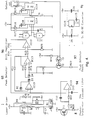
- FIG. 4 An embodiment of the detector circuit 9 is shown in Figure 4. This circuit has been designed to ensure the function of the breathing detector even by unsymmetrical and strongly disturbed breathing cycles.
- Figure 4 contains a ⁇ 5 volts converter circuit 91 and a drive circuit 1 for the laser diode D1.
- the signal received by the photo transistor T1 (corresponding to designation no. 8 in Figure 1) is brought to a low pass filter 94 with the cutoff frequency 5 Hz.
- the filtered signal is coupled to a peak-detector 95 built up of two operational amplifiers.
- a differential amplifier 96 the difference is then formed between the signals on the peak-detector in- and outputs.
- the amplifier stage is followed by a pulse shaper consisting of two successive NAND-gates (IC 11). From the first NAND-gate a monostable multivibrator MV 1 is triggered with the pulse length of 6 seconds.
- NAND-gate is coupled via a derivating net to the reset input of the mono flip-flop. The result will be that the 6-second pulse of the mono flip-flop is interrupted when the signal goes down which occurs by exhalation. If however, the expiration signal fails because of interference, or arrives too late, the time of 6 seconds will run out and the mono flip-flop resets.
- an additional mono flip-flop MV 2 of the pulse length 0,1 seconds follows, the mission of which is to reset the peak-detector 95 via two field effect transistors 97 so that a new inhalation phase can be started.
- the output signal from the circuit is constituted by 0,1 second long pulses of time intervals that constitute a measure of the breathing rate.
- the output signal can be connected to a frequency counter for conversion to a breathing rate after an appropriate number of pulses according to conventional technique. It can also be used direct to control an acoustic signal or presented on a display, which also can be done with the analogue breathing signal, which in that case suitably is extracted after the differential amplifier 96.
- the circuit according to Figure 4 is adapted to a detector according to Figure 2, in which reflected light from the sensor surface is detected. If instead transmitted light from the sensor according to Figure 3 is detected, the same circuit can be used on condition that the signal is inverted.
Landscapes
- Health & Medical Sciences (AREA)
- Life Sciences & Earth Sciences (AREA)
- Pulmonology (AREA)
- Medical Informatics (AREA)
- Surgery (AREA)
- Biophysics (AREA)
- Pathology (AREA)
- Engineering & Computer Science (AREA)
- Biomedical Technology (AREA)
- Heart & Thoracic Surgery (AREA)
- Physiology (AREA)
- Molecular Biology (AREA)
- Physics & Mathematics (AREA)
- Animal Behavior & Ethology (AREA)
- General Health & Medical Sciences (AREA)
- Public Health (AREA)
- Veterinary Medicine (AREA)
- Measurement Of The Respiration, Hearing Ability, Form, And Blood Characteristics Of Living Organisms (AREA)
- Investigating Or Analysing Materials By Optical Means (AREA)
- Fire-Detection Mechanisms (AREA)
Abstract
Description

- Figure 1
- diagrammatically shows a device according to the invention
- Figures 2 and 3
- show different embodiments of breathing sensors according to the invention,
- Figure 4
- shows an example of a circuit diagram which can be utilized at devices according to the invention,
- Figures 5 and 6
- show further embodiments of breathing sensors according to the invention, and
- Figure 5b
- shows a holder for an optical fibre and an oxygen catheter.
| Component list to Fig. 4. | |
| Des. | Type/Value |
| IC11 | 4093 |
| IC12 | IR 3C02 |
| IC13 | TLC 274 |
| IC14 | 4538 |
| IC15 | 7660 |
| T1 | TEYT5500 |
| T2, | 2N3820 |
| R7 | |
| 22 Ω | |
| R8 | 1.5 kΩ |
| | 5 kΩ |
| R10 | 2.7 kΩ/20° |
| R11 | |
| 20 kΩ | |
| | 1 MΩ |
| R13 | 10 kΩ |
| R14,R15 | 1 kΩ |
| R16,R17,R19 | 100 kΩ |
| R18 | 1.2 MΩ |
| R20 | 4.7 kΩ |
| R21 | 27 kΩ |
| R23 | 10 kΩ |
| R22,R24,R25 | 100 kΩ |
| | 22 µF |
| C7 | O.47 µF |
| C8,C9 | 100 nF |
| C10 | 4.7 |
| C11 | |
| 1 µF | |
| C12 | 0.68 µF |
| C13 | 0.33 µF |
| C14,C15, | 10 µF |
| L1 | 47 µH |
| D1 | LT022MC |
| D2,D3,D4 | 1N4148 |
| D5 | 1N4004 |
Claims (9)
- Method for sensing the breathing, including the steps ofplacing a breathing sensor in a breathing air flow;emitting an optical signal to the breathing sensor;detecting the transmitted and /or reflected optical signal changed by moisture deposited on the breathing sensor;coupling out signal variation created by moisture deposited on the breathing sensor from the detected signal; andconverting the coupled out signal part to a measure of breathing.
- Method according to claim 1, characterized in that the optical signal is transmitted to the breathing sensor via an optical conductor, that the end surface of the conductor constitutes a sensor surface, that changes in the reflected optical signal at the end surface are sensed and that the breathing is indicated as a function of the changes.
- Method according to claim 1, characterized in that the optical signal is transmitted to the breathing sensor via an optical conductor, that a portion of the conductor surface forms a window which constitutes a sensor surface, that changes in the transmitted optical signal in the conductor past the window are sensed and that the breathing is indicated as a function of the changes.
- Device for sensing the breathing, comprisinga breathing sensor with a sensor surface (51, 53) adapted to be placed in a breathing air flow;means (1, 2) for emitting an optical signal to the sensor surface;means (8) for detecting the transmitted and/or reflected optical signal changeable by moisture deposited on the sensor surface (51, 53);means (9) for coupling out signal variation created by moisture deposited on the sensor surface from the detected signal; andmeans for processing and converting the coupled out signal part to a measure of breathing.
- Device according to claim 4, characterized in that the sensor surface is constituted by the end surface (51) of an optical conductor (5) transmitting the optical signal.
- Device according to claim 5, characterized in that the end surface (51) is arranged essentially perpendicular to the optical conductor.
- Device according to claim 4, characterized in that the sensor surface is constituted by a portion (53) of an optical conductor that forms a window which derives a part of the signal transmitted in the optical conductor.
- Device according to claim 4, characterized by means (9) to sense extreme values in the optical signal from the sensor and means (10, 11) to indicate the breathing rate after a predetermined number of sensed extreme values.
- Device according to claim 8, characterized by means to emit an alarm of a ceasing breath a predetermined period after an extreme value of the optical signal from the sensor has been sensed, if no new extreme value before then is reached.
Applications Claiming Priority (3)
| Application Number | Priority Date | Filing Date | Title |
|---|---|---|---|
| SE9300137A SE470564B (en) | 1993-01-19 | 1993-01-19 | Method and apparatus for sensing the breathing of a human or animal |
| SE9300137 | 1993-01-19 | ||
| PCT/SE1994/000037 WO1994016620A1 (en) | 1993-01-19 | 1994-01-19 | Method, sensor and device to sense breathing |
Publications (2)
| Publication Number | Publication Date |
|---|---|
| EP0681453A1 EP0681453A1 (en) | 1995-11-15 |
| EP0681453B1 true EP0681453B1 (en) | 1998-08-12 |
Family
ID=20388581
Family Applications (1)
| Application Number | Title | Priority Date | Filing Date |
|---|---|---|---|
| EP94905297A Expired - Lifetime EP0681453B1 (en) | 1993-01-19 | 1994-01-19 | Method and device to sense breathing |
Country Status (9)
| Country | Link |
|---|---|
| US (1) | US5676154A (en) |
| EP (1) | EP0681453B1 (en) |
| JP (1) | JPH09504184A (en) |
| CN (1) | CN1089227C (en) |
| AU (1) | AU696521B2 (en) |
| DE (1) | DE69412457T2 (en) |
| ES (1) | ES2124391T3 (en) |
| SE (1) | SE470564B (en) |
| WO (1) | WO1994016620A1 (en) |
Families Citing this family (23)
| Publication number | Priority date | Publication date | Assignee | Title |
|---|---|---|---|---|
| DE19621627C1 (en) * | 1996-05-30 | 1997-09-18 | Bosch Gmbh Robert | Moisture detector for vehicle windscreen |
| US6418876B1 (en) | 1997-07-02 | 2002-07-16 | Alfa Laval Agri Ab | Method and an apparatus for monitoring an animal |
| SE513761C2 (en) * | 1997-07-18 | 2000-10-30 | Optovent Ab | Method and apparatus for sensing breathing |
| US6185446B1 (en) * | 1998-08-21 | 2001-02-06 | William F. Carlsen, Jr. | Method and apparatus for monitoring the breathing of a patient during magnetic resonance imaging |
| TW453865B (en) * | 2000-05-23 | 2001-09-11 | Optovent Ab | Apparatus and method for monitoring a patient's breath and supplying a gas or gases different from ambient air to the patient, and nose adapter for the apparatus |
| WO2002034129A1 (en) * | 2000-10-24 | 2002-05-02 | Optovent Ab | Capacity stress testing method and apparatus |
| US7052470B2 (en) * | 2002-02-11 | 2006-05-30 | Gannon Mark D | Breathing detection/confirmation device |
| US7364553B2 (en) * | 2002-12-20 | 2008-04-29 | Amidex, Inc. | Breath aerosol management and collection system |
| US7101341B2 (en) | 2003-04-15 | 2006-09-05 | Ross Tsukashima | Respiratory monitoring, diagnostic and therapeutic system |
| US7166201B2 (en) * | 2003-12-01 | 2007-01-23 | Sierra Medical Technology | Self-condensing pH sensor |
| US7037272B2 (en) * | 2004-07-26 | 2006-05-02 | Ohlan Silpachai | Infant respiratory monitoring system |
| WO2006037331A1 (en) | 2004-10-04 | 2006-04-13 | Statchip Aps | A handheld home monitoring sensors network device |
| US9138168B2 (en) * | 2006-04-13 | 2015-09-22 | Universita Campus Bio-Medico Di Roma | Apparatus and method for videorhinohygrometric (VRI) measures |
| GB2448323A (en) * | 2007-04-10 | 2008-10-15 | Mark Sinclair Varney | Respiratory Rate Measuring Apparatus |
| NZ707067A (en) * | 2009-02-11 | 2016-11-25 | Resmed Ltd | Acoustic detection for respiratory treatment apparatus |
| CN101756702B (en) * | 2009-12-31 | 2015-05-27 | 马宇尘 | Respiratory detector component and detector realizing method based on electronic tag |
| EP3452157B1 (en) * | 2016-05-03 | 2020-07-15 | Koninklijke Philips N.V. | Detecting combustion of a nasal cannula |
| CN106618577A (en) * | 2016-09-22 | 2017-05-10 | 西北工业大学 | Optical fiber breath sensor based on molybdenum disulfide nanometer coating |
| CN106730222B (en) * | 2016-12-28 | 2023-03-07 | 盐城师范学院 | Oxygen mask with respiration sensor |
| CN109738366A (en) * | 2018-12-28 | 2019-05-10 | 林亭妤 | For sensing device existing for moisture absorption core excreta |
| WO2021130202A1 (en) | 2019-12-23 | 2021-07-01 | Koninklijke Philips N.V. | A patch cable, a breathing adapter, and a respiratory gas detection system for detecting a concentration of a respiratory gas |
| US20230380717A1 (en) * | 2022-05-31 | 2023-11-30 | Gentex Corporation | Respiration monitoring system using a structured light |
| CN116849606B (en) * | 2023-05-31 | 2026-04-28 | 复旦大学附属中山医院厦门医院 | A non-invasive nasal cavity heating and humidification function testing instrument and testing method |
Family Cites Families (10)
| Publication number | Priority date | Publication date | Assignee | Title |
|---|---|---|---|---|
| US3863502A (en) * | 1970-03-12 | 1975-02-04 | Stanley B Elliott | Visual-type hygrometer |
| US4166891A (en) * | 1972-04-19 | 1979-09-04 | Elliott Stanley B | Visual-type hygrometer |
| DE2938856A1 (en) * | 1979-09-26 | 1981-04-16 | Gesellschaft für Strahlen- und Umweltforschung mbH, 8000 München | METHOD AND DEVICE FOR DETERMINING THE DEPOSITION OF PARTICLES IN THE BREATHING TRACT AND / OR FOR CHECKING THE FUNCTION OF THE BREATHING AREA |
| US4634856A (en) * | 1984-08-03 | 1987-01-06 | The United States Of America As Represented By The United States Department Of Energy | Fiber optic moisture sensor with moisture-absorbing reflective target |
| US4641524A (en) * | 1985-08-15 | 1987-02-10 | Kms Fusion, Inc. | Optical humidity sensor |
| FR2604890A1 (en) * | 1986-10-14 | 1988-04-15 | Thomson Csf | OPTICAL DEVICE FOR THE SIMULTANEOUS DETECTION OF HEART MOVEMENT AND BREATHING AND ITS USE IN THE SYNCHRONIZATION OF NUCLEAR MAGNETIC RESONANCE ACQUISITION IMAGING DEVICES |
| EP0309666A1 (en) * | 1987-09-29 | 1989-04-05 | Siemens Aktiengesellschaft | Method and device for monitoring respiration |
| DE4011065A1 (en) * | 1990-04-05 | 1991-10-10 | Hellige Gmbh | DEVICE FOR BREATHING MONITORING |
| WO1992018848A1 (en) * | 1991-04-23 | 1992-10-29 | Introlab Pty. Limited | A moisture sensor |
| US5319975A (en) * | 1992-07-16 | 1994-06-14 | Rutgers, The State University Of New Jersey | Fiber optic moisture sensor |
-
1993
- 1993-01-19 SE SE9300137A patent/SE470564B/en not_active IP Right Cessation
-
1994
- 1994-01-19 ES ES94905297T patent/ES2124391T3/en not_active Expired - Lifetime
- 1994-01-19 US US08/492,001 patent/US5676154A/en not_active Expired - Lifetime
- 1994-01-19 CN CN94190954.9A patent/CN1089227C/en not_active Expired - Fee Related
- 1994-01-19 JP JP6516919A patent/JPH09504184A/en active Pending
- 1994-01-19 EP EP94905297A patent/EP0681453B1/en not_active Expired - Lifetime
- 1994-01-19 AU AU58952/94A patent/AU696521B2/en not_active Ceased
- 1994-01-19 WO PCT/SE1994/000037 patent/WO1994016620A1/en not_active Ceased
- 1994-01-19 DE DE69412457T patent/DE69412457T2/en not_active Expired - Fee Related
Also Published As
| Publication number | Publication date |
|---|---|
| EP0681453A1 (en) | 1995-11-15 |
| AU696521B2 (en) | 1998-09-10 |
| SE9300137D0 (en) | 1993-01-19 |
| SE470564B (en) | 1994-08-29 |
| CN1116404A (en) | 1996-02-07 |
| CN1089227C (en) | 2002-08-21 |
| DE69412457T2 (en) | 1999-01-28 |
| ES2124391T3 (en) | 1999-02-01 |
| JPH09504184A (en) | 1997-04-28 |
| DE69412457D1 (en) | 1998-09-17 |
| WO1994016620A1 (en) | 1994-08-04 |
| US5676154A (en) | 1997-10-14 |
| SE9300137L (en) | 1994-07-20 |
| AU5895294A (en) | 1994-08-15 |
Similar Documents
| Publication | Publication Date | Title |
|---|---|---|
| AU696521B2 (en) | Method, sensor and device to sense breathing | |
| US12127834B2 (en) | Soft boot pulse oximetry sensor | |
| JP4842509B2 (en) | Optical guidance system for placement of invasive catheters | |
| US6161537A (en) | Transtracheal energy application and sensing system for intubation: method and apparatus | |
| US7992573B2 (en) | Optically guided system for precise placement of a medical catheter in a patient | |
| US8376952B2 (en) | Method and apparatus for sensing blood oxygen | |
| US4757194A (en) | Methods and apparatus for sensing the mechanical application of force | |
| US7603152B2 (en) | Physiological stress detector device and system | |
| JP2807650B2 (en) | Equipment for tissue characterization | |
| US20080039715A1 (en) | Three-dimensional optical guidance for catheter placement | |
| US4727886A (en) | Inhalation detection apparatus | |
| CN103221981A (en) | A presence detection system and a lighting system | |
| US4928703A (en) | Non-contact respiration rate and apnea monitor using pulmonary gas exchange technique | |
| WO2005010567A2 (en) | Low profile fiber optic vital signs sensor | |
| US7052470B2 (en) | Breathing detection/confirmation device | |
| Burch et al. | The phlebomanometer: A new apparatus for direct measurement of vanous pressure in large and small veins | |
| JPS5831522Y2 (en) | Fukugogataseitaijiyouhokenshiyutsuki | |
| AU2005301172A2 (en) | Optically guided system for precise placement of a medical catheter in a patient | |
| JPH04188048A (en) | moisture detector | |
| JPH0448534Y2 (en) | ||
| ES271240Y (en) | ENTERIC FEED PROBE. | |
| JPH0744925B2 (en) | Light source device for endoscope | |
| GB2620662A (en) | Improvements in or relating to remotely capturing biometric data | |
| Babchenko et al. | Fiber optic sensor for the assessment of breathing effort | |
| Elhaj et al. | Designing an automatic subglottic suction for prevention of ventilator-associated pneumonia |
Legal Events
| Date | Code | Title | Description |
|---|---|---|---|
| PUAI | Public reference made under article 153(3) epc to a published international application that has entered the european phase |
Free format text: ORIGINAL CODE: 0009012 |
|
| 17P | Request for examination filed |
Effective date: 19950821 |
|
| AK | Designated contracting states |
Kind code of ref document: A1 Designated state(s): BE DE ES FR GB IT NL SE |
|
| 17Q | First examination report despatched |
Effective date: 19970814 |
|
| GRAG | Despatch of communication of intention to grant |
Free format text: ORIGINAL CODE: EPIDOS AGRA |
|
| GRAG | Despatch of communication of intention to grant |
Free format text: ORIGINAL CODE: EPIDOS AGRA |
|
| GRAH | Despatch of communication of intention to grant a patent |
Free format text: ORIGINAL CODE: EPIDOS IGRA |
|
| GRAH | Despatch of communication of intention to grant a patent |
Free format text: ORIGINAL CODE: EPIDOS IGRA |
|
| GRAA | (expected) grant |
Free format text: ORIGINAL CODE: 0009210 |
|
| AK | Designated contracting states |
Kind code of ref document: B1 Designated state(s): BE DE ES FR GB IT NL SE |
|
| ITF | It: translation for a ep patent filed | ||
| REF | Corresponds to: |
Ref document number: 69412457 Country of ref document: DE Date of ref document: 19980917 |
|
| ET | Fr: translation filed | ||
| REG | Reference to a national code |
Ref country code: ES Ref legal event code: FG2A Ref document number: 2124391 Country of ref document: ES Kind code of ref document: T3 |
|
| PLBE | No opposition filed within time limit |
Free format text: ORIGINAL CODE: 0009261 |
|
| STAA | Information on the status of an ep patent application or granted ep patent |
Free format text: STATUS: NO OPPOSITION FILED WITHIN TIME LIMIT |
|
| 26N | No opposition filed | ||
| REG | Reference to a national code |
Ref country code: GB Ref legal event code: IF02 |
|
| PGFP | Annual fee paid to national office [announced via postgrant information from national office to epo] |
Ref country code: ES Payment date: 20030130 Year of fee payment: 10 |
|
| PGFP | Annual fee paid to national office [announced via postgrant information from national office to epo] |
Ref country code: NL Payment date: 20030131 Year of fee payment: 10 |
|
| PGFP | Annual fee paid to national office [announced via postgrant information from national office to epo] |
Ref country code: BE Payment date: 20030204 Year of fee payment: 10 |
|
| PG25 | Lapsed in a contracting state [announced via postgrant information from national office to epo] |
Ref country code: ES Free format text: LAPSE BECAUSE OF NON-PAYMENT OF DUE FEES Effective date: 20040120 |
|
| PG25 | Lapsed in a contracting state [announced via postgrant information from national office to epo] |
Ref country code: BE Free format text: LAPSE BECAUSE OF NON-PAYMENT OF DUE FEES Effective date: 20040131 |
|
| BERE | Be: lapsed |
Owner name: *OPTOVENT A.B. Effective date: 20040131 |
|
| PG25 | Lapsed in a contracting state [announced via postgrant information from national office to epo] |
Ref country code: NL Free format text: LAPSE BECAUSE OF NON-PAYMENT OF DUE FEES Effective date: 20040801 |
|
| NLV4 | Nl: lapsed or anulled due to non-payment of the annual fee |
Effective date: 20040801 |
|
| REG | Reference to a national code |
Ref country code: ES Ref legal event code: FD2A Effective date: 20040120 |
|
| PGFP | Annual fee paid to national office [announced via postgrant information from national office to epo] |
Ref country code: DE Payment date: 20090126 Year of fee payment: 16 |
|
| PGFP | Annual fee paid to national office [announced via postgrant information from national office to epo] |
Ref country code: GB Payment date: 20090127 Year of fee payment: 16 |
|
| PGFP | Annual fee paid to national office [announced via postgrant information from national office to epo] |
Ref country code: SE Payment date: 20090119 Year of fee payment: 16 Ref country code: IT Payment date: 20090123 Year of fee payment: 16 |
|
| PGFP | Annual fee paid to national office [announced via postgrant information from national office to epo] |
Ref country code: FR Payment date: 20090130 Year of fee payment: 16 |
|
| GBPC | Gb: european patent ceased through non-payment of renewal fee |
Effective date: 20100119 |
|
| EUG | Se: european patent has lapsed | ||
| REG | Reference to a national code |
Ref country code: FR Ref legal event code: ST Effective date: 20100930 |
|
| PG25 | Lapsed in a contracting state [announced via postgrant information from national office to epo] |
Ref country code: FR Free format text: LAPSE BECAUSE OF NON-PAYMENT OF DUE FEES Effective date: 20100201 |
|
| PG25 | Lapsed in a contracting state [announced via postgrant information from national office to epo] |
Ref country code: DE Free format text: LAPSE BECAUSE OF NON-PAYMENT OF DUE FEES Effective date: 20100803 |
|
| PG25 | Lapsed in a contracting state [announced via postgrant information from national office to epo] |
Ref country code: GB Free format text: LAPSE BECAUSE OF NON-PAYMENT OF DUE FEES Effective date: 20100119 |
|
| PG25 | Lapsed in a contracting state [announced via postgrant information from national office to epo] |
Ref country code: IT Free format text: LAPSE BECAUSE OF NON-PAYMENT OF DUE FEES Effective date: 20100119 |
|
| PG25 | Lapsed in a contracting state [announced via postgrant information from national office to epo] |
Ref country code: SE Free format text: LAPSE BECAUSE OF NON-PAYMENT OF DUE FEES Effective date: 20100120 |