EP0679805B1 - Windturbine mit senkrechter Achse - Google Patents
Windturbine mit senkrechter Achse Download PDFInfo
- Publication number
- EP0679805B1 EP0679805B1 EP93116588A EP93116588A EP0679805B1 EP 0679805 B1 EP0679805 B1 EP 0679805B1 EP 93116588 A EP93116588 A EP 93116588A EP 93116588 A EP93116588 A EP 93116588A EP 0679805 B1 EP0679805 B1 EP 0679805B1
- Authority
- EP
- European Patent Office
- Prior art keywords
- blade
- wind
- stabilizer
- cross
- axis
- Prior art date
- Legal status (The legal status is an assumption and is not a legal conclusion. Google has not performed a legal analysis and makes no representation as to the accuracy of the status listed.)
- Expired - Lifetime
Links
- 239000003381 stabilizer Substances 0.000 claims description 39
- 238000006073 displacement reaction Methods 0.000 claims description 6
- 238000009826 distribution Methods 0.000 claims description 2
- 230000008901 benefit Effects 0.000 description 7
- 230000014509 gene expression Effects 0.000 description 6
- 230000002093 peripheral effect Effects 0.000 description 5
- 238000004458 analytical method Methods 0.000 description 4
- OENHQHLEOONYIE-JLTXGRSLSA-N β-Carotene Chemical compound CC=1CCCC(C)(C)C=1\C=C\C(\C)=C\C=C\C(\C)=C\C=C\C=C(/C)\C=C\C=C(/C)\C=C\C1=C(C)CCCC1(C)C OENHQHLEOONYIE-JLTXGRSLSA-N 0.000 description 4
- 238000012937 correction Methods 0.000 description 3
- 239000008186 active pharmaceutical agent Substances 0.000 description 2
- 238000013461 design Methods 0.000 description 2
- 238000010586 diagram Methods 0.000 description 2
- 230000007246 mechanism Effects 0.000 description 2
- 238000000034 method Methods 0.000 description 2
- 230000001133 acceleration Effects 0.000 description 1
- 230000009471 action Effects 0.000 description 1
- 230000000903 blocking effect Effects 0.000 description 1
- 238000004364 calculation method Methods 0.000 description 1
- 230000008859 change Effects 0.000 description 1
- 230000008878 coupling Effects 0.000 description 1
- 238000010168 coupling process Methods 0.000 description 1
- 238000005859 coupling reaction Methods 0.000 description 1
- 230000000694 effects Effects 0.000 description 1
- 238000011156 evaluation Methods 0.000 description 1
- 238000000605 extraction Methods 0.000 description 1
- 239000012530 fluid Substances 0.000 description 1
- 238000009472 formulation Methods 0.000 description 1
- 238000012423 maintenance Methods 0.000 description 1
- 238000004519 manufacturing process Methods 0.000 description 1
- 239000000203 mixture Substances 0.000 description 1
- 244000045947 parasite Species 0.000 description 1
- 238000005192 partition Methods 0.000 description 1
- 230000002035 prolonged effect Effects 0.000 description 1
- 230000009467 reduction Effects 0.000 description 1
- 102220047090 rs6152 Human genes 0.000 description 1
- 238000009987 spinning Methods 0.000 description 1
Images


Classifications
-
- F—MECHANICAL ENGINEERING; LIGHTING; HEATING; WEAPONS; BLASTING
- F03—MACHINES OR ENGINES FOR LIQUIDS; WIND, SPRING, OR WEIGHT MOTORS; PRODUCING MECHANICAL POWER OR A REACTIVE PROPULSIVE THRUST, NOT OTHERWISE PROVIDED FOR
- F03D—WIND MOTORS
- F03D3/00—Wind motors with rotation axis substantially perpendicular to the air flow entering the rotor
- F03D3/06—Rotors
- F03D3/062—Rotors characterised by their construction elements
- F03D3/066—Rotors characterised by their construction elements the wind engaging parts being movable relative to the rotor
- F03D3/067—Cyclic movements
-
- F—MECHANICAL ENGINEERING; LIGHTING; HEATING; WEAPONS; BLASTING
- F03—MACHINES OR ENGINES FOR LIQUIDS; WIND, SPRING, OR WEIGHT MOTORS; PRODUCING MECHANICAL POWER OR A REACTIVE PROPULSIVE THRUST, NOT OTHERWISE PROVIDED FOR
- F03D—WIND MOTORS
- F03D3/00—Wind motors with rotation axis substantially perpendicular to the air flow entering the rotor
- F03D3/06—Rotors
- F03D3/061—Rotors characterised by their aerodynamic shape, e.g. aerofoil profiles
-
- F—MECHANICAL ENGINEERING; LIGHTING; HEATING; WEAPONS; BLASTING
- F03—MACHINES OR ENGINES FOR LIQUIDS; WIND, SPRING, OR WEIGHT MOTORS; PRODUCING MECHANICAL POWER OR A REACTIVE PROPULSIVE THRUST, NOT OTHERWISE PROVIDED FOR
- F03D—WIND MOTORS
- F03D7/00—Controlling wind motors
- F03D7/06—Controlling wind motors the wind motors having rotation axis substantially perpendicular to the air flow entering the rotor
-
- F—MECHANICAL ENGINEERING; LIGHTING; HEATING; WEAPONS; BLASTING
- F05—INDEXING SCHEMES RELATING TO ENGINES OR PUMPS IN VARIOUS SUBCLASSES OF CLASSES F01-F04
- F05B—INDEXING SCHEME RELATING TO WIND, SPRING, WEIGHT, INERTIA OR LIKE MOTORS, TO MACHINES OR ENGINES FOR LIQUIDS COVERED BY SUBCLASSES F03B, F03D AND F03G
- F05B2240/00—Components
- F05B2240/20—Rotors
- F05B2240/21—Rotors for wind turbines
- F05B2240/211—Rotors for wind turbines with vertical axis
- F05B2240/214—Rotors for wind turbines with vertical axis of the Musgrove or "H"-type
-
- F—MECHANICAL ENGINEERING; LIGHTING; HEATING; WEAPONS; BLASTING
- F05—INDEXING SCHEMES RELATING TO ENGINES OR PUMPS IN VARIOUS SUBCLASSES OF CLASSES F01-F04
- F05B—INDEXING SCHEME RELATING TO WIND, SPRING, WEIGHT, INERTIA OR LIKE MOTORS, TO MACHINES OR ENGINES FOR LIQUIDS COVERED BY SUBCLASSES F03B, F03D AND F03G
- F05B2260/00—Function
- F05B2260/70—Adjusting of angle of incidence or attack of rotating blades
- F05B2260/72—Adjusting of angle of incidence or attack of rotating blades by turning around an axis parallel to the rotor centre line
-
- Y—GENERAL TAGGING OF NEW TECHNOLOGICAL DEVELOPMENTS; GENERAL TAGGING OF CROSS-SECTIONAL TECHNOLOGIES SPANNING OVER SEVERAL SECTIONS OF THE IPC; TECHNICAL SUBJECTS COVERED BY FORMER USPC CROSS-REFERENCE ART COLLECTIONS [XRACs] AND DIGESTS
- Y02—TECHNOLOGIES OR APPLICATIONS FOR MITIGATION OR ADAPTATION AGAINST CLIMATE CHANGE
- Y02E—REDUCTION OF GREENHOUSE GAS [GHG] EMISSIONS, RELATED TO ENERGY GENERATION, TRANSMISSION OR DISTRIBUTION
- Y02E10/00—Energy generation through renewable energy sources
- Y02E10/70—Wind energy
- Y02E10/74—Wind turbines with rotation axis perpendicular to the wind direction
Definitions
- the invention concerns a mechanical device which converts the wind energy into rotational mechanical energy, and in particular a cross-wind-axis wind turbine.
- Cross-wind-axis wind turbines with orientable blades are predicted to have power coefficients greater than for any other wind turbine exceeding the theoretical maximum of 0.593 of propeller type wind-axis wind turbines, due to the fact, that the rotor projected area into the wind is crosssed two times by each blade during one revolution, duplicating the effective working area and decelerating a larger portion of the wind than does a propeller type wind-axis wind turbine of the same projected area of rotor disk.
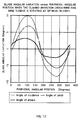
- the pitch angle of each blade must be continuosly changed during rotation according to the instantaneous peripheral angular position of the blade, to optimize the angle of attack between the chord of the airfoil-shaped cross section of the blade and the changing incidence angle of the relative wind.
- the amplitude of this angular pitch variation must vary with the celerity or "tip speed ratio" ⁇ , (which is the relationship between the peripheral tangential speed of the blade V tB , divided by the wind speed V0), in order to comply with the amplitude variation of the blade relative wind incidence angle ⁇ B with said celerity.
- the invention aims to maximize the great energy production capability of cross-wind-axis wind turbines, by totally matching the pitch angle control of each individual blade, with an extremely simple method.
- An additional orientable aerodynamic surface or stabilizer is mechanically linked to each blade, so dimensioned and positioned, that, as the rotor revolves, the aerodynamic lift forces created by the relative wind over the blade and the stabilizer, will produce opposing pitching moments about their respective pivot axis, and as result of their mechanical interconnection, both surfaces will pivot simultaneously and essentially parallel to each other, into an optimun pitch angle, where said opposing pitching moments equilibrate each other.
- each blade and of its respective stabilizer occurs instantaneously, assuring a perfect coupling and synchronization to the changing direction of the actuating relative wind, at any celerity.
- the tangential components of the lift forces created by the relative wind over the blade and the stabilizer have the same direction, so that, their combined action will induce an added positive torque to spin up the rotor.
- the invention expected real peak power coefficient of 0.70 represents a 50 % increase in comparison to the real peak power coefficient of a propeller type wind turbine and 16 % increase above the peak power coefficient of the Cyclogyro.
- This advantage added to the mechanical simplicity of the invention constitutes a real breakthrough, which will make more feasible the wide use of the wind energy. Further advantages of the invention will become apparent from a consideration of the drawings and ensuing description thereof.
- Fig.1, Fig.2, Fig.3 and Fig.4 The prefered embodiment of the invention, shown in multiple views in Fig.1, Fig.2, Fig.3 and Fig.4, is characterized by having each blade [2] supported at almost equally spaced intermediate points by a rotor structure [1] comprising two radial arms per blade.
- FIG.5 Another suitable embodiment of the invention, shown in perspective view in Fig.5, is aimed to reduce the additional cost and weight of the two radial arms per blade and is characterized by having each blade [2] linked to its respective stabilizer [3] by means of a flexible element [4] such as a teethed timing belt or a roller chain, hidden inside the supporting structure [1].
- the blades and stabilizers are tapered to improve their strenght, and are supported at their pivot shafts in their central partitions.
- This embodiment do not share the advantages of the preferred embodiment, but due to its clean design, the power coefficient is the same, considering the less drag produced by the single arm rotor structure [1].
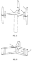
- FIG. 6 Another suitable embodiment of the invention, shown in Fig. 6, is characterized by having each blade [2] and each stabilizer [3] the same lenght, being supported at their outer ends by a double arm rotor structure [1]. Both surfaces are linked by means of a flexible element [4] such as a teethed timing belt or a roller chain, hidden inside the rotor structure [1].
- the height of the rotor is comparatively much smaller than the diameter. This embodiment is more suitable to take advantage of very high wind speeds, for example when the rotor is mounted on a vehicle.
- the invention consists of a cross-wind-axis rotor structure [1], having multiple orientable aerodynamic surfaces or blades [2] around its periphery, mounted parallel to the rotor axis and fastened to the rotor structure [1], by first pivoting fastening means [5];being each of said blades [2], interconnected by means of means for transfering angular displacement [4] with another orientable aerodynamic surface or stabilizer [3],mounted on the same rotor radial as the blade, at a radius which is not less than 50% of the rotor radius and fastened to the rotor structure [1], by second pivoting fastening means [6]; so that during rotation, said blade [2] and said stabilizer [3] are able to pivot simultanously and essentially parallel to each other around their respective pivot axis.
- the blade pivot axis crosses the blade mean aerodynamic chord[C B ], at a point between the leading edge and the aerodynamic center of pressure [7], of the airfoil-shaped blade cross section. Shown in Fig.9.
- the stabilizer pivot axis crosses the stabilizer mean aerodynamic chord [C S ], at a point between the trailing edge and the aerodynamic center of pressure [8], of the airfoil-shaped stabilizer cross section. Shown in Fig.9.
- the weight distribution of the interconnected assembly comprising the blade [2], the stabilizer [3] and the means for transfering angular displacement [4], is dynamically balanced to avoid an unfavorable displacement due to the centrifugal force.
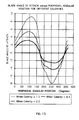
- the lift coefficient of the blade C LB which is a function of the blade angle of attack ⁇ B , is a direct expression of this wind blockage, since it must be admitted that if the angle of attack would be zero, the lift coefficient would also be zero and no lift force would be induced on the blade, the wind in consequence would pass undisturbed through the rotor.
Claims (4)
- Windturbine mit Drehachse rechtwinklig zur Windrichtung, deren antreibendes Element eine zur Windrichtung rechtwinklige Drehachse einer Rotor-Struktur (1) aufweist mit vielfach ausrichtbaren aerodynamischen Flächen oder Flügeln (2) am äußeren Umfang, die mittels ersten schwenkbaren Befestigungseinrichtungen (5) parallel zu der Drehachse montiert und an der Rotor-Struktur (1) befestigt sind, wobei jeder der Flügel (2) mittels Einrichtungen zur Übertragung von Winkeländerungen (4) mit einer anderen ausrichtbaren aerodynamischen Fläche oder Stabilisator (3) verbunden ist, die an dem selben Rotor radial wie der Flügel mit einem Radius montiert ist, der nicht weniger als 50% des Rotorradius beträgt und an die Rotorstruktur (1) befestigt mit zweiten schwenkbaren Befestigungseinrichtungen (6) ist, so daß während der Drehung dieser Flügel (2) und dieser Stabilisator (3) gleichzeitig schwenken können,
dadurch gekennzeichnet, daß die zweiten schwenkbaren Befestigungseinrichtungen diesen Flügel (2) und diesen Stabilisator (3) in die Lage versetzen, parallel zueinander um ihre jeweiligen Schwenkachsen zu schwenken, wobei sie sich ausrichten zu einem Anstellwinkel, bei dem die entgegengesetzten Anstellmomente, die von den aerodynamischen Auftriebskräften über diesen Flügel (2) und diesen Stabilisator (3) erzeugt werden, einander ausgleichen, und bei dem die aerodynamischen Auftriebskräfte optimal sind, um das erforderliche Drehmoment zur Drehung des Rotors zu induzieren. - Windturbine mit Drehachse rechtwinklig zur Windrichtung gemäß Anspruch 1, dadurch gekennzeichnet, daß die Schwenkachse des Flügels die mittlere aerodynamische Profilsehne [CB] des Flügels an einem Punkt kreuzt zwischen der vorderen Kante und dem aerodynamischen Druckpunkt [7] des luftprofilförmigen Querschnitts des Flügels.
- Windturbine mit Drehachse rechtwinklig zur Windrichtung gemäß Anspruch 1, dadurch gekennzeichnet, daß die Schwenkachse des Stabilisators die mittlere aerodynamische Profilsehne [CS] des Stabilisators an einem Punkt kreuzt zwischen der nachfolgenden Kante und dem aerodynamischen Druckpunkt [8] des luftprofilförmigen Querschnitts des Stabilisators.
- Windturbine mit Drehachse rechtwinklig zur Windrichtung gemäß Anspruch 1, dadurch gekennzeichnet, daß die Masseverteilung der verbundenen Einheit, die den Flügel (2), den Stabilisator (3) und die Einrichtungen zur Übertragung der Winkelverschiebung (4) enthalten, dynamisch ausgeglichen ist, um eine ungünstige Verschiebung auf grund zentrifugaler Kraft zu vermeiden.
Priority Applications (4)
| Application Number | Priority Date | Filing Date | Title |
|---|---|---|---|
| DK93116588.0T DK0679805T3 (da) | 1993-10-14 | 1993-10-14 | Tværvindsakse-vindturbine |
| DE69301094T DE69301094T2 (de) | 1993-10-14 | 1993-10-14 | Windturbine mit senkrechter Achse |
| EP93116588A EP0679805B1 (de) | 1993-10-14 | 1993-10-14 | Windturbine mit senkrechter Achse |
| US08/313,392 US5518367A (en) | 1993-10-14 | 1994-09-27 | Cross-wind-axis wind turbine |
Applications Claiming Priority (1)
| Application Number | Priority Date | Filing Date | Title |
|---|---|---|---|
| EP93116588A EP0679805B1 (de) | 1993-10-14 | 1993-10-14 | Windturbine mit senkrechter Achse |
Publications (2)
| Publication Number | Publication Date |
|---|---|
| EP0679805A1 EP0679805A1 (de) | 1995-11-02 |
| EP0679805B1 true EP0679805B1 (de) | 1995-12-20 |
Family
ID=8213343
Family Applications (1)
| Application Number | Title | Priority Date | Filing Date |
|---|---|---|---|
| EP93116588A Expired - Lifetime EP0679805B1 (de) | 1993-10-14 | 1993-10-14 | Windturbine mit senkrechter Achse |
Country Status (4)
| Country | Link |
|---|---|
| US (1) | US5518367A (de) |
| EP (1) | EP0679805B1 (de) |
| DE (1) | DE69301094T2 (de) |
| DK (1) | DK0679805T3 (de) |
Families Citing this family (37)
| Publication number | Priority date | Publication date | Assignee | Title |
|---|---|---|---|---|
| AU3876397A (en) * | 1996-08-23 | 1998-03-06 | Dragoljub Perunicic | Motor propulsion unit having improved efficiency |
| BE1011612A6 (fr) * | 1997-12-15 | 1999-11-09 | Adant Pierre Paul | Turbine eolienne a axe transversal. |
| US6394745B1 (en) * | 2000-05-26 | 2002-05-28 | Saeed Quraeshi | Straight-bladed vertical axis wind turbine |
| LV12775B (lv) * | 2001-01-05 | 2002-02-20 | Leon�ds NIKITINS | Rotortipa vēja dzinējs |
| DE10128438B4 (de) * | 2001-05-03 | 2006-09-28 | Wobben, Aloys, Dipl.-Ing. | Windenergieanlage |
| JP3330141B1 (ja) * | 2001-11-09 | 2002-09-30 | 学校法人東海大学 | 一体型風水車とその製造方法 |
| US7094017B2 (en) | 2002-05-16 | 2006-08-22 | Hidemi Kurita | Vertical shaft driving device for vertical wind mills or the like and electric power generator using the same |
| KR20040013662A (ko) * | 2002-08-07 | 2004-02-14 | 원인호 | 양력 면적을 조절할 수 있게 한 대칭익형 양날개의 구성과회전장치 |
| US20040247438A1 (en) * | 2003-02-20 | 2004-12-09 | Mccoin Dan Keith | Wind energy conversion system |
| US6952058B2 (en) | 2003-02-20 | 2005-10-04 | Wecs, Inc. | Wind energy conversion system |
| GB2404227B (en) * | 2003-07-24 | 2006-02-01 | Xc02 Conisbee Ltd | Vertical-axis wind turbine |
| US20070134094A1 (en) * | 2005-12-08 | 2007-06-14 | Stephen Gregory | Rotor apparatus and turbine system incorporating same |
| ITBZ20070022A1 (it) * | 2007-05-24 | 2008-11-25 | Ropatec Srl | Ala per turbine eoliche ad asse di rotazione verticale |
| US20090148290A1 (en) * | 2007-06-06 | 2009-06-11 | Garver Theodore M | Wind turbine and method of operating same |
| US20090053060A1 (en) * | 2007-06-06 | 2009-02-26 | Garver Theodore M | Wind turbine blade control system |
| US7766602B1 (en) | 2007-12-13 | 2010-08-03 | Stroburg Eldon L | Windmill with pivoting blades |
| US8215897B2 (en) * | 2007-12-17 | 2012-07-10 | Douglass Karl J | Cylindrical wind turbine |
| PL216244B1 (pl) * | 2008-02-08 | 2014-03-31 | Anew Inst Społka Z Ograniczoną Odpowiedzialnością | Wirnik turbiny wiatrowej o pionowej osi obrotu |
| US8133026B2 (en) * | 2008-07-02 | 2012-03-13 | Richard J. Groll | Fixed horizontal axis-mounted wind turbine blade with an independently rotating pressure cambered fin |
| US20100014973A1 (en) * | 2008-07-19 | 2010-01-21 | Carlos Manuel Perez Romo | Vertical Axis Fluid Flow Turbine System |
| US8143738B2 (en) * | 2008-08-06 | 2012-03-27 | Infinite Wind Energy LLC | Hyper-surface wind generator |
| US8593008B2 (en) * | 2008-10-03 | 2013-11-26 | Noel Richard Potter | Variable vane vertical axis wind turbine |
| WO2010071850A2 (en) * | 2008-12-19 | 2010-06-24 | Higher Dimension Materials, Inc. | Multi-rotor vertical axis wind turbine |
| CN101832225B (zh) * | 2009-03-12 | 2014-06-11 | 严强 | 升力型垂直轴风力发电机风轮结构 |
| EP2258940B1 (de) * | 2009-06-02 | 2013-03-13 | Penn Anneliese | Windkraftstation mit einem Darrieus-Rotor |
| US20110110779A1 (en) * | 2009-11-06 | 2011-05-12 | Thomas Glenn Stephens | Fluid turbine featuring articulated blades and phase-adjusted cam |
| DE102010016086A1 (de) * | 2010-03-23 | 2011-11-24 | Anneliese Penn | Rotorblatt für H-Rotor |
| WO2011122895A2 (ko) * | 2010-04-01 | 2011-10-06 | 정맥산업개발(주) | 유체를 이용한 동력발생장치 |
| US20120061968A1 (en) * | 2010-09-10 | 2012-03-15 | Burrell Leo Leroy | Burrell compound axial windmill |
| US9394046B2 (en) | 2011-11-16 | 2016-07-19 | Ecological Energy Company | Fluid interface device as well as apparati and methods including same |
| CN103452751A (zh) * | 2012-11-05 | 2013-12-18 | 上海理工大学 | 垂直轴风力机 |
| DE102013008919B4 (de) * | 2013-05-24 | 2017-12-07 | Magdeburger Windkraftanlagen GmbH | Rotorsystem für die Energiewandlung von kinetischer Energie in Fluiden und Massenströmen |
| JP6398095B2 (ja) * | 2014-02-14 | 2018-10-03 | 上野 康男 | 動力装置 |
| US10316824B2 (en) * | 2015-05-07 | 2019-06-11 | Scharf Energy LLC | Camber changing and low drag wing for vertical axis wind turbine |
| ES2882590T3 (es) * | 2016-03-11 | 2021-12-02 | Gratzer Louis B | Cicloturbina eólica |
| US20180363624A1 (en) * | 2017-06-14 | 2018-12-20 | Arken S.P.A. | Wind turbine with pairs of blades to deflect airflow |
| WO2021231106A1 (en) * | 2020-05-11 | 2021-11-18 | XFlow Energy Company | Separable fluid turbine rotor |
Family Cites Families (15)
| Publication number | Priority date | Publication date | Assignee | Title |
|---|---|---|---|---|
| US1076713A (en) * | 1912-02-07 | 1913-10-28 | William H Southwick | Air or water motor. |
| CA1114296A (en) * | 1977-06-21 | 1981-12-15 | Witold Brzozowski | Wind energy convertor |
| US4247253A (en) * | 1977-07-07 | 1981-01-27 | Gakko Hojin Tokai University | Vertical axis wind turbine |
| US4247251A (en) * | 1978-05-17 | 1981-01-27 | Wuenscher Hans F | Cycloidal fluid flow engine |
| AT359007B (de) * | 1978-10-11 | 1980-10-10 | Wiener Brueckenbau | Windkraftmaschine |
| DE3018211C2 (de) * | 1980-05-13 | 1986-04-30 | Eisenwerke Kaiserslautern Entwicklungsgesellschaft mbH, 6750 Kaiserslautern | Windrad |
| GB2082260B (en) * | 1980-08-20 | 1984-01-25 | Nianbilla Co Ltd | Vertical axis windmill |
| JPS5857082A (ja) * | 1981-10-01 | 1983-04-05 | Shigefumi Mori | 風胴内両方向性空気力軸タ−ビン |
| US4430044A (en) * | 1981-11-23 | 1984-02-07 | Liljegren L Kenyon | Vertical axis wind turbine |
| US4415312A (en) * | 1982-03-11 | 1983-11-15 | Wixlin, Inc. | Transverse axis fluid turbine |
| DE3300083A1 (de) * | 1983-01-04 | 1984-07-26 | Erich Herter | Turbine zur umsetzung von insbesondere windenergie |
| FR2564616A1 (fr) * | 1984-05-17 | 1985-11-22 | Mariani Antoine | Plan porteur a incidence automatique |
| DE3626917A1 (de) * | 1986-06-03 | 1987-12-10 | Erich Herter | Windturbine |
| US5256034A (en) * | 1991-04-19 | 1993-10-26 | Sultzbaugh John S | Variable pitch propeller for use in conjunction with a vertical axis wind turbine |
| US5193978A (en) * | 1991-09-23 | 1993-03-16 | Bill Gutierrez | Articulated blade with automatic pitch and camber control |
-
1993
- 1993-10-14 EP EP93116588A patent/EP0679805B1/de not_active Expired - Lifetime
- 1993-10-14 DK DK93116588.0T patent/DK0679805T3/da active
- 1993-10-14 DE DE69301094T patent/DE69301094T2/de not_active Expired - Fee Related
-
1994
- 1994-09-27 US US08/313,392 patent/US5518367A/en not_active Expired - Lifetime
Also Published As
| Publication number | Publication date |
|---|---|
| EP0679805A1 (de) | 1995-11-02 |
| DE69301094D1 (de) | 1996-02-01 |
| DK0679805T3 (da) | 1996-05-13 |
| DE69301094T2 (de) | 1996-12-19 |
| US5518367A (en) | 1996-05-21 |
Similar Documents
| Publication | Publication Date | Title |
|---|---|---|
| EP0679805B1 (de) | Windturbine mit senkrechter Achse | |
| US4533297A (en) | Rotor system for horizontal axis wind turbines | |
| CA2608425C (en) | Vertical axis wind turbines | |
| US4082479A (en) | Overspeed spoilers for vertical axis wind turbine | |
| US4715776A (en) | Wind turbine system using a savonius type rotor | |
| US6069409A (en) | Wind powered generator apparatus | |
| US5405246A (en) | Vertical-axis wind turbine with a twisted blade configuration | |
| US4430044A (en) | Vertical axis wind turbine | |
| GB2210934A (en) | Wind turbine system using twin savonius-type rotors | |
| US4204805A (en) | Vertical axis wind turbine | |
| US4083651A (en) | Wind turbine with automatic pitch and yaw control | |
| US7762776B2 (en) | Vortex shedding cyclical propeller | |
| US4582013A (en) | Self-adjusting wind power machine | |
| US4105363A (en) | Overspeed control arrangement for vertical axis wind turbines | |
| US5527151A (en) | Advanced wind turbine with lift-destroying aileron for shutdown | |
| US7424988B2 (en) | Use of aerodynamic forces to assist in the control and positioning of aircraft control surfaces and variable geometry systems | |
| US20080258469A1 (en) | Wind driven power generator with moveable cam | |
| EP2057351A2 (de) | Windbetriebener stromgenerator | |
| WO2010030895A2 (en) | Wind turbine | |
| US4537559A (en) | Venturi rotor apparatus for the generation of power | |
| US4799860A (en) | Wind-energy converter | |
| WO2008053282A1 (en) | Windturbine | |
| CA1045038A (en) | Vertical axis wind turbine | |
| EP2957768A1 (de) | Verbesserte Windturbine mit vertikaler Achse | |
| EP0506749A4 (en) | Wind turbine |
Legal Events
| Date | Code | Title | Description |
|---|---|---|---|
| PUAI | Public reference made under article 153(3) epc to a published international application that has entered the european phase |
Free format text: ORIGINAL CODE: 0009012 |
|
| 17P | Request for examination filed |
Effective date: 19940510 |
|
| AK | Designated contracting states |
Kind code of ref document: A1 Designated state(s): DE DK ES FR GB NL |
|
| GRAA | (expected) grant |
Free format text: ORIGINAL CODE: 0009210 |
|
| AK | Designated contracting states |
Kind code of ref document: B1 Designated state(s): DE DK ES FR GB NL |
|
| PG25 | Lapsed in a contracting state [announced via postgrant information from national office to epo] |
Ref country code: NL Free format text: LAPSE BECAUSE OF FAILURE TO SUBMIT A TRANSLATION OF THE DESCRIPTION OR TO PAY THE FEE WITHIN THE PRESCRIBED TIME-LIMIT Effective date: 19951220 Ref country code: ES Free format text: THE PATENT HAS BEEN ANNULLED BY A DECISION OF A NATIONAL AUTHORITY Effective date: 19951220 |
|
| REF | Corresponds to: |
Ref document number: 69301094 Country of ref document: DE Date of ref document: 19960201 |
|
| ET | Fr: translation filed | ||
| REG | Reference to a national code |
Ref country code: DK Ref legal event code: T3 |
|
| NLV1 | Nl: lapsed or annulled due to failure to fulfill the requirements of art. 29p and 29m of the patents act | ||
| ET1 | Fr: translation filed ** revision of the translation of the patent or the claims | ||
| PLBE | No opposition filed within time limit |
Free format text: ORIGINAL CODE: 0009261 |
|
| STAA | Information on the status of an ep patent application or granted ep patent |
Free format text: STATUS: NO OPPOSITION FILED WITHIN TIME LIMIT |
|
| 26N | No opposition filed | ||
| PGFP | Annual fee paid to national office [announced via postgrant information from national office to epo] |
Ref country code: GB Payment date: 20010925 Year of fee payment: 9 |
|
| PGFP | Annual fee paid to national office [announced via postgrant information from national office to epo] |
Ref country code: FR Payment date: 20011018 Year of fee payment: 9 |
|
| REG | Reference to a national code |
Ref country code: GB Ref legal event code: IF02 |
|
| PG25 | Lapsed in a contracting state [announced via postgrant information from national office to epo] |
Ref country code: GB Free format text: LAPSE BECAUSE OF NON-PAYMENT OF DUE FEES Effective date: 20021014 |
|
| GBPC | Gb: european patent ceased through non-payment of renewal fee |
Effective date: 20021014 |
|
| PG25 | Lapsed in a contracting state [announced via postgrant information from national office to epo] |
Ref country code: FR Free format text: LAPSE BECAUSE OF NON-PAYMENT OF DUE FEES Effective date: 20030630 |
|
| REG | Reference to a national code |
Ref country code: FR Ref legal event code: ST |
|
| PGFP | Annual fee paid to national office [announced via postgrant information from national office to epo] |
Ref country code: DK Payment date: 20040426 Year of fee payment: 11 |
|
| PG25 | Lapsed in a contracting state [announced via postgrant information from national office to epo] |
Ref country code: DK Free format text: LAPSE BECAUSE OF NON-PAYMENT OF DUE FEES Effective date: 20041101 |
|
| REG | Reference to a national code |
Ref country code: DK Ref legal event code: EBP |
|
| PGFP | Annual fee paid to national office [announced via postgrant information from national office to epo] |
Ref country code: DE Payment date: 20051117 Year of fee payment: 13 |
|
| PG25 | Lapsed in a contracting state [announced via postgrant information from national office to epo] |
Ref country code: DE Free format text: LAPSE BECAUSE OF NON-PAYMENT OF DUE FEES Effective date: 20070501 |