EP0679002A2 - Card reading configuration in a mobile phone - Google Patents
Card reading configuration in a mobile phone Download PDFInfo
- Publication number
- EP0679002A2 EP0679002A2 EP95302605A EP95302605A EP0679002A2 EP 0679002 A2 EP0679002 A2 EP 0679002A2 EP 95302605 A EP95302605 A EP 95302605A EP 95302605 A EP95302605 A EP 95302605A EP 0679002 A2 EP0679002 A2 EP 0679002A2
- Authority
- EP
- European Patent Office
- Prior art keywords
- card
- battery unit
- housing
- space
- mobile phone
- Prior art date
- Legal status (The legal status is an assumption and is not a legal conclusion. Google has not performed a legal analysis and makes no representation as to the accuracy of the status listed.)
- Withdrawn
Links
Images

Classifications
-
- H—ELECTRICITY
- H04—ELECTRIC COMMUNICATION TECHNIQUE
- H04B—TRANSMISSION
- H04B1/00—Details of transmission systems, not covered by a single one of groups H04B3/00 - H04B13/00; Details of transmission systems not characterised by the medium used for transmission
- H04B1/38—Transceivers, i.e. devices in which transmitter and receiver form a structural unit and in which at least one part is used for functions of transmitting and receiving
- H04B1/3816—Mechanical arrangements for accommodating identification devices, e.g. cards or chips; with connectors for programming identification devices
-
- G—PHYSICS
- G06—COMPUTING; CALCULATING OR COUNTING
- G06K—GRAPHICAL DATA READING; PRESENTATION OF DATA; RECORD CARRIERS; HANDLING RECORD CARRIERS
- G06K13/00—Conveying record carriers from one station to another, e.g. from stack to punching mechanism
- G06K13/18—Conveying record carriers from one station to another, e.g. from stack to punching mechanism the record carrier being longitudinally extended, e.g. punched tape
- G06K13/24—Guiding of record carriers; Recognising end of record carrier
-
- G—PHYSICS
- G06—COMPUTING; CALCULATING OR COUNTING
- G06K—GRAPHICAL DATA READING; PRESENTATION OF DATA; RECORD CARRIERS; HANDLING RECORD CARRIERS
- G06K7/00—Methods or arrangements for sensing record carriers, e.g. for reading patterns
- G06K7/0013—Methods or arrangements for sensing record carriers, e.g. for reading patterns by galvanic contacts, e.g. card connectors for ISO-7816 compliant smart cards or memory cards, e.g. SD card readers
- G06K7/0021—Methods or arrangements for sensing record carriers, e.g. for reading patterns by galvanic contacts, e.g. card connectors for ISO-7816 compliant smart cards or memory cards, e.g. SD card readers for reading/sensing record carriers having surface contacts
-
- G—PHYSICS
- G06—COMPUTING; CALCULATING OR COUNTING
- G06K—GRAPHICAL DATA READING; PRESENTATION OF DATA; RECORD CARRIERS; HANDLING RECORD CARRIERS
- G06K7/00—Methods or arrangements for sensing record carriers, e.g. for reading patterns
- G06K7/0013—Methods or arrangements for sensing record carriers, e.g. for reading patterns by galvanic contacts, e.g. card connectors for ISO-7816 compliant smart cards or memory cards, e.g. SD card readers
- G06K7/0056—Methods or arrangements for sensing record carriers, e.g. for reading patterns by galvanic contacts, e.g. card connectors for ISO-7816 compliant smart cards or memory cards, e.g. SD card readers housing of the card connector
- G06K7/006—Methods or arrangements for sensing record carriers, e.g. for reading patterns by galvanic contacts, e.g. card connectors for ISO-7816 compliant smart cards or memory cards, e.g. SD card readers housing of the card connector the housing being a portable casing
-
- H—ELECTRICITY
- H04—ELECTRIC COMMUNICATION TECHNIQUE
- H04B—TRANSMISSION
- H04B1/00—Details of transmission systems, not covered by a single one of groups H04B3/00 - H04B13/00; Details of transmission systems not characterised by the medium used for transmission
- H04B1/38—Transceivers, i.e. devices in which transmitter and receiver form a structural unit and in which at least one part is used for functions of transmitting and receiving
- H04B1/3827—Portable transceivers
- H04B1/3883—Arrangements for mounting batteries or battery chargers
-
- H—ELECTRICITY
- H04—ELECTRIC COMMUNICATION TECHNIQUE
- H04M—TELEPHONIC COMMUNICATION
- H04M1/00—Substation equipment, e.g. for use by subscribers
- H04M1/02—Constructional features of telephone sets
- H04M1/0202—Portable telephone sets, e.g. cordless phones, mobile phones or bar type handsets
-
- H—ELECTRICITY
- H04—ELECTRIC COMMUNICATION TECHNIQUE
- H04M—TELEPHONIC COMMUNICATION
- H04M1/00—Substation equipment, e.g. for use by subscribers
- H04M1/02—Constructional features of telephone sets
- H04M1/0202—Portable telephone sets, e.g. cordless phones, mobile phones or bar type handsets
- H04M1/026—Details of the structure or mounting of specific components
- H04M1/0262—Details of the structure or mounting of specific components for a battery compartment
-
- H—ELECTRICITY
- H04—ELECTRIC COMMUNICATION TECHNIQUE
- H04M—TELEPHONIC COMMUNICATION
- H04M2250/00—Details of telephonic subscriber devices
- H04M2250/14—Details of telephonic subscriber devices including a card reading device
Definitions
- the invention relates to a card reading configuration in a mobile phone, more specifically to a card reading configuration for reading a subscriber card of the size of a credit card in a battery-driven small-sized mobile phone.
- SIM card For the operation of the phone, some mobile phone systems require an information card, "SIM card", which is inserted in its reading unit for subscriber identification, among other functions.
- the basic SIM card is a card complying with ISO 7816 standard, which is of the size of an ordinary credit card, i.e. with a width of c. 54 mm and a length of c. 84 mm.
- the applicant's former EP patent application 522 762 discloses a configuration, illustrated in Figures 1 and 2, in which the card space and the contacts required for reading the card are disposed such that the battery unit acts as a cover fitting over the space.
- the objective of the present invention is to further improve this set-up so as to provide a reliable card reading configuration which is easy to operate and requires a minimum of space.
- the present invention provides a mobile phone comprising: a housing having a space for receiving a card; a battery unit slidably engageable with the housing to close off the space, the battery unit including a first stopper means for bearing against a rear edge of the card during sliding engagement with the housing, whereby to positively locate the card.
- a card reading configuration in a mobile phone comprising a space for the card in the housing, the space being covered by the battery unit as it is put into position, and being laterally defined by the side walls of the housing, and provided with contacts joining matching contact areas in the card with the card in position, characterized in that it comprises: guide grooves in the side walls of the space, which the edges of the card engage as the card is being inserted, and serving to position the card laterally and to stop the card essentially totally from moving in any other direction than the longitudinal direction of the card and the housing, a stop in the housing, which serves to position the card and to limit its movement in the said longitudinal direction as the card is being inserted, matching guide members in the battery unit and in the housing, which require the battery unit to be pushed in the said longitudinal direction at the end of its insertion, a first stopper means in the battery unit, which at the end of the insertion of the battery unit presses against the rear edge of the card relative to the pushing direction, thus forcing the card into
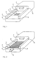
- FIGS 1 to 4 are schematic views of the card reading configuration and its operation in a mobile phone according to the invention.
- the Figures show the parts of the mobile phone alone that are necessary for illustrating the invention.
- the mobile phone housing 1 is provided with a space 11 for the SIM card 8 to be covered by the battery unit 9, the space being laterally defined by the side walls 2 of the housing 1 and the transverse wall 15, and having a plane surface 3, onto which the card is placed.
- the plane surface has an opening for a connector 4, which is provided with contacts 5, which, with the card in position, will join corresponding contact areas in the card, not illustrated in the Figures.
- the side walls 2 are provided with guide grooves 6, defined by the plane surface 3 on one side, the card edges 8 engaging these grooves as the card is being inserted into position in the longitudinal direction of the mobile phone and the card, indicated by arrow A in Figure 2.
- the guide grooves 6 serve to position the card in the lateral direction, and to stop it essentially totally from moving in any other direction than the longitudinal one.
- the battery unit 9 has a design such that, while being fitted into position, it has eventually to be pushed in the longitudinal direction indicated by arrow A, as illustrated in Figure 3.
- the rear end of the battery unit 9 relative to the pushing direction is provided with guides 10 engaging the guide grooves 6 over a distance not occupied by the card.
- the battery unit 9 is provided with means which, as the card is being inserted, will press against its rear edge relative to the direction of insertion of the card 8, and thus will press the card 8 into the correct position, with the front end of the card facing a stop in the housing 1.
- the stop consists of the wall 15 of the compartment 11 placed in the front end relative to the insertion direction A.
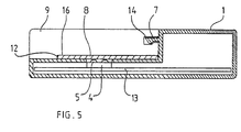
- the rear end of the battery unit 9 may be provided with a shoulder 12 acting as a stopper means, for instance as illustrated in Figure 5, and this shoulder may cover the entire width of the battery unit 9, and may be joined by the front ends of the guides 10.
- the longitudinal section shown in Figure 6 also shows schematically a circuit card within the housing 1, with a connector 4 connected to the circuit card, and also matching locking means 7 and 14 in the housing and in the battery unit, by means of which the battery unit is locked to the housing when pushed into position.
- the housing 1 is equipped with a locking tongue 7, which engages a matching recess 14 in the battery unit.
- the battery unit 9 being in position, its lower surface 16 will keep the card 8 pressed against the contacts 5.
- a battery unit design which involves pushing in the longitudinal direction at the end of insertion, can be implemented in various ways, and is not confined to the guide arrangement of this embodiment.
- the stop in the housing limiting the movement of the card and the stopper means in the battery unit may also vary in many ways within the scope of the invention.
Landscapes
- Engineering & Computer Science (AREA)
- Signal Processing (AREA)
- Physics & Mathematics (AREA)
- General Physics & Mathematics (AREA)
- Theoretical Computer Science (AREA)
- Artificial Intelligence (AREA)
- Computer Vision & Pattern Recognition (AREA)
- Computer Networks & Wireless Communication (AREA)
- Telephone Set Structure (AREA)
Abstract
Description
- The invention relates to a card reading configuration in a mobile phone, more specifically to a card reading configuration for reading a subscriber card of the size of a credit card in a battery-driven small-sized mobile phone.
- For the operation of the phone, some mobile phone systems require an information card, "SIM card", which is inserted in its reading unit for subscriber identification, among other functions. The basic SIM card is a card complying with ISO 7816 standard, which is of the size of an ordinary credit card, i.e. with a width of c. 54 mm and a length of c. 84 mm.
- Recent developments in mobile phone systems allow subscribers to increasingly use very small battery-driven handsets, "pocket phones", with a typical size of 60 x 170 x 25 mm. This kind of phones have in fact become extremely popular. A conventional card reading arrangement is obviously not adequate for reading an ISO standard card in such a small mobile phone, the conventional design being a casing surrounding the card on all sides except for the insertion opening, and provided with contacts for card reading and a connection to the electronics that carry out the actual reading. The present situation calls for solutions enabling the space required for the card reader in a mobile phone to be reduced to a minimum size.
- The applicant's former EP patent application 522 762 discloses a configuration, illustrated in Figures 1 and 2, in which the card space and the contacts required for reading the card are disposed such that the battery unit acts as a cover fitting over the space. The objective of the present invention is to further improve this set-up so as to provide a reliable card reading configuration which is easy to operate and requires a minimum of space.
- To achieve this objective, in a first aspect the present invention provides a mobile phone comprising:
a housing having a space for receiving a card;
a battery unit slidably engageable with the housing to close off the space,
the battery unit including a first stopper means for bearing against a rear edge of the card during sliding engagement with the housing, whereby to positively locate the card. - In accordance with a second aspect of the present invention provides a card reading configuration in a mobile phone, comprising a space for the card in the housing, the space being covered by the battery unit as it is put into position, and being laterally defined by the side walls of the housing, and provided with contacts joining matching contact areas in the card with the card in position, characterized in that it comprises:
guide grooves in the side walls of the space, which the edges of the card engage as the card is being inserted, and serving to position the card laterally and to stop the card essentially totally from moving in any other direction than the longitudinal direction of the card and the housing,
a stop in the housing, which serves to position the card and to limit its movement in the said longitudinal direction as the card is being inserted,
matching guide members in the battery unit and in the housing, which require the battery unit to be pushed in the said longitudinal direction at the end of its insertion,
a first stopper means in the battery unit, which at the end of the insertion of the battery unit presses against the rear edge of the card relative to the pushing direction, thus forcing the card into the positioned location determined by the guide grooves and the stop, with the battery unit in position, and
a second stopper means in the battery unit, which presses against the card and keep it pressed against the contacts when the battery unit is in position. - Subsidiary features of the invention are given in the dependent claims.
- One embodiment of the invention will be described in further detail below, with reference to the accompanying drawings, in which:
- Figure 1 is a schematic perspective view of the mobile phone housing, implementing one embodiment of the card reading configuration of the invention,
- Figure 2 is a similar view of the mobile phone housing illustrated in Figure 1, with the card inserted approximately in position,
- Figure 3 is a similar view illustrating the battery unit being put into position in the mobile phone housing, with the card approximately positioned as illustrated in Figure 2,
- Figure 4 is a similar view of a mobile phone with the battery unit in position and with the card enclosed in the mobile phone; and
- Figure 5 is a schematic view of a longitudinal section of a mobile phone, with the SIM card in place in the embodiment of the card reading configuration of the invention illustrated here.
- Figures 1 to 4 are schematic views of the card reading configuration and its operation in a mobile phone according to the invention. The Figures show the parts of the mobile phone alone that are necessary for illustrating the invention. The
mobile phone housing 1 is provided with aspace 11 for theSIM card 8 to be covered by thebattery unit 9, the space being laterally defined by theside walls 2 of thehousing 1 and thetransverse wall 15, and having aplane surface 3, onto which the card is placed. The plane surface has an opening for a connector 4, which is provided withcontacts 5, which, with the card in position, will join corresponding contact areas in the card, not illustrated in the Figures. Theside walls 2 are provided withguide grooves 6, defined by theplane surface 3 on one side, thecard edges 8 engaging these grooves as the card is being inserted into position in the longitudinal direction of the mobile phone and the card, indicated by arrow A in Figure 2. Theguide grooves 6 serve to position the card in the lateral direction, and to stop it essentially totally from moving in any other direction than the longitudinal one. - The
battery unit 9 has a design such that, while being fitted into position, it has eventually to be pushed in the longitudinal direction indicated by arrow A, as illustrated in Figure 3. In the embodiment illustrated by Figures 1 to 4, the rear end of thebattery unit 9 relative to the pushing direction is provided withguides 10 engaging theguide grooves 6 over a distance not occupied by the card. In addition, thebattery unit 9 is provided with means which, as the card is being inserted, will press against its rear edge relative to the direction of insertion of thecard 8, and thus will press thecard 8 into the correct position, with the front end of the card facing a stop in thehousing 1. - As illustrated by the Figures, in this embodiment the stop consists of the
wall 15 of thecompartment 11 placed in the front end relative to the insertion direction A. The rear end of thebattery unit 9 may be provided with ashoulder 12 acting as a stopper means, for instance as illustrated in Figure 5, and this shoulder may cover the entire width of thebattery unit 9, and may be joined by the front ends of theguides 10. The longitudinal section shown in Figure 6 also shows schematically a circuit card within thehousing 1, with a connector 4 connected to the circuit card, and also matching locking means 7 and 14 in the housing and in the battery unit, by means of which the battery unit is locked to the housing when pushed into position. In the embodiment described here, thehousing 1 is equipped with alocking tongue 7, which engages amatching recess 14 in the battery unit. Thebattery unit 9 being in position, itslower surface 16 will keep thecard 8 pressed against thecontacts 5. - The following advantages are achieved with the described embodiment of the invention: an economic design easy to use, which does not require extra parts and no moving mechanical parts at all for the reader; a card reader configuration that requires a minimum space in the mobile phone; a configuration ensuring correct positioning of the card, even if the user does not insert it with proper care, and after insertion, firm retention of the card.
- It will be appreciated by those skilled in the art that a battery unit design, which involves pushing in the longitudinal direction at the end of insertion, can be implemented in various ways, and is not confined to the guide arrangement of this embodiment. Similarly, the stop in the housing limiting the movement of the card and the stopper means in the battery unit may also vary in many ways within the scope of the invention.
Claims (4)
- A mobile phone comprising:
a housing (1) having a space (11) for receiving a card (8);
a battery unit (9) slidably engageable with the housing (1) to close off the space (11),
the battery unit (9) including a first stopper means (12) for bearing against a rear edge of the card during sliding engagement with the housing, whereby to positively locate the card. - A mobile phone as in Claim 1, wherein the battery unit (9) comprises a second stopper means (16) for pressing against a face of the card, whereby to further positively locate the card.
- A mobile phone as in Claim 1 or 2, wherein the space (11) is defined by a support surface (3) and side walls (2), the side walls including formations for entraining opposed edges of a card during said sliding engagement.
- A card reading configuration in a mobile phone, comprising a space (11) for the card (8) in the housing (1), the space (11) being covered by the battery unit (9) as it is put into position, and being laterally defined by the side walls (2) of the housing (1), and provided with contacts (5) joining matching contact areas in the card with the card (8) in position, characterized in that it comprises:
guide grooves (6) in the side walls (2) of the space (11), which the edges of the card (8) engage as the card is being inserted, and serving to position the card laterally and to stop the card essentially totally from moving in any other direction than the longitudinal direction (A) of the card and the housing,
a stop (15) in the housing (1), which serves to position the card and to limit its movement in the said longitudinal direction (A) as the card (8) is being inserted,
matching guide members (10, 6) in the battery unit (9) and in the housing (1), which require the battery unit to be pushed in the said longitudinal direction (A) at the end of its insertion,
a first stopper means (12) in the battery unit (9), which at the end of the insertion of the battery unit presses against the rear edge of the card (8) relative to the pushing direction (A), thus forcing the card into the positioned location determined by the guide grooves (6) and the stop (15), with the battery unit (9) in position, and
a second stopper means (16) in the battery unit (9), which presses against the card (8) and keep it pressed against the contacts (5) when the battery unit is in position.
Applications Claiming Priority (2)
| Application Number | Priority Date | Filing Date | Title |
|---|---|---|---|
| FI941812A FI98178C (en) | 1994-04-19 | 1994-04-19 | Card reading device for mobile phone |
| FI941812 | 1994-04-19 |
Publications (2)
| Publication Number | Publication Date |
|---|---|
| EP0679002A2 true EP0679002A2 (en) | 1995-10-25 |
| EP0679002A3 EP0679002A3 (en) | 1996-01-17 |
Family
ID=8540557
Family Applications (1)
| Application Number | Title | Priority Date | Filing Date |
|---|---|---|---|
| EP95302605A Withdrawn EP0679002A3 (en) | 1994-04-19 | 1995-04-19 | Card reading configuration in a mobile phone. |
Country Status (3)
| Country | Link |
|---|---|
| US (1) | US5669069A (en) |
| EP (1) | EP0679002A3 (en) |
| FI (1) | FI98178C (en) |
Cited By (9)
| Publication number | Priority date | Publication date | Assignee | Title |
|---|---|---|---|---|
| EP0893777A2 (en) * | 1997-07-25 | 1999-01-27 | Nokia Mobile Phones Ltd. | A data card housing |
| GB2335461A (en) * | 1998-01-21 | 1999-09-22 | Motorola Inc | Battery pack housing with fixed latch(es) at each end |
| WO2000014671A1 (en) * | 1998-09-04 | 2000-03-16 | Ic Tv Interactive Cyber Television Inc. | Remote smart battery |
| US6102743A (en) * | 1997-07-25 | 2000-08-15 | Nokia Mobile Phones Ltd. | Data card connector |
| EP1116284A1 (en) * | 1999-07-23 | 2001-07-18 | Cyril C. K. Chaing | Battery card and electrical apparatus using same battery card assembly |
| WO2004021472A1 (en) * | 2002-08-28 | 2004-03-11 | Nokia Corporation | Battery holder |
| EP1646208A1 (en) * | 2004-10-08 | 2006-04-12 | Samsung Electronics Co., Ltd. | SIM/UIM card socket in slidable portable wireless terminal |
| EP1715661A2 (en) * | 2005-04-18 | 2006-10-25 | Samsung Electronics Co., Ltd. | Slide module for slide type portable terminal and cover apparatus therefor |
| CN101437059B (en) * | 2008-12-03 | 2011-12-28 | 捷开通讯科技(上海)有限公司 | Pulling/inserting structure for client personal identification card and mobile phone apparatus thereof |
Families Citing this family (22)
| Publication number | Priority date | Publication date | Assignee | Title |
|---|---|---|---|---|
| US6798882B2 (en) | 1995-09-28 | 2004-09-28 | Nokia Mobile Phones Limited | Mobile station |
| FR2743464A1 (en) * | 1996-01-10 | 1997-07-11 | Philips Electronics Nv | APPARATUS HAVING A REMOVABLE HOUSING CONTAINING AN ADAPTER FOR READING DIFFERENT FORMAT OF CHIP CARDS |
| FR2743463A1 (en) * | 1996-01-10 | 1997-07-11 | Philips Electronics Nv | APPARATUS PROVIDED WITH AN ADAPTER FOR READING DIFFERENT FORMAT OF CHIP CARDS |
| JP3606498B2 (en) | 1996-04-26 | 2005-01-05 | 三菱電機株式会社 | Portable information terminal device |
| US5883786A (en) * | 1996-12-31 | 1999-03-16 | Ericsson, Inc. | SIM card containment assembly for an electronic apparatus |
| CA2293393C (en) * | 1997-06-16 | 2006-03-21 | Swisscom Ag | Mobile device, chip card and method of communication |
| FI104928B (en) | 1997-11-27 | 2000-04-28 | Nokia Mobile Phones Ltd | Wireless Communication and a Method of Making a Wireless Communication Device |
| GB2331866B (en) | 1997-11-28 | 2001-08-29 | Nokia Mobile Phones Ltd | Radiotelephone |
| EP0924867A3 (en) * | 1997-12-22 | 2002-03-06 | Siemens Aktiengesellschaft | Card reader for mobile transceivers |
| FI980303A (en) * | 1998-02-10 | 1999-08-11 | Nokia Mobile Phones Ltd | Packaging |
| FI980603A (en) * | 1998-03-18 | 1999-09-19 | Nokia Mobile Phones Ltd | Hinged electronic device |
| AUPP411098A0 (en) * | 1998-06-15 | 1998-07-09 | Newcom Technologies Pty Ltd | Communication method and apparatus improvements |
| GB2338811B (en) | 1998-06-26 | 2002-10-02 | Nokia Mobile Phones Ltd | A cardholder |
| JP3391375B2 (en) * | 1999-03-02 | 2003-03-31 | 日本電気株式会社 | Battery for mobile phone with IC card |
| US6490443B1 (en) | 1999-09-02 | 2002-12-03 | Automated Business Companies | Communication and proximity authorization systems |
| SE520091C2 (en) * | 2000-09-25 | 2003-05-20 | Jarlab Jarl Larsson Ab | Functional control system and business monitoring for service providers |
| US8529341B2 (en) * | 2004-07-27 | 2013-09-10 | Igt | Optically sensitive display for a gaming apparatus |
| US8079904B2 (en) * | 2004-08-20 | 2011-12-20 | Igt | Gaming access card with display |
| KR100668677B1 (en) * | 2005-12-10 | 2007-01-12 | 한국전자통신연구원 | Portable mobile communication terminal |
| US20090138876A1 (en) * | 2007-11-22 | 2009-05-28 | Hsuan-Yeh Chang | Method and system for delivering application packages based on user demands |
| US9990673B2 (en) * | 2010-05-03 | 2018-06-05 | Symbol Technologies, Llc | Universal payment module systems and methods for mobile computing devices |
| DE102014217347A1 (en) * | 2014-08-29 | 2016-03-03 | Sennheiser Electronic Gmbh & Co. Kg | Wireless pocket transmitter, accumulator unit for a wireless bodypack transmitter, wireless microphone, accumulator for a wireless microphone and charging unit for a bodypack transmitter and / or a microphone |
Citations (3)
| Publication number | Priority date | Publication date | Assignee | Title |
|---|---|---|---|---|
| EP0475210A2 (en) * | 1990-09-10 | 1992-03-18 | Siemens Aktiengesellschaft | Card read device for electric-communication engineering |
| EP0505932A2 (en) * | 1991-03-28 | 1992-09-30 | Hagenuk Telecom GmbH | Holder for insertable chip card |
| US5252815A (en) * | 1990-10-08 | 1993-10-12 | Alcatel Cit | Compact smart card reader with unitary case and connector cover |
Family Cites Families (7)
| Publication number | Priority date | Publication date | Assignee | Title |
|---|---|---|---|---|
| US5109540A (en) * | 1989-05-01 | 1992-04-28 | Motorola, Inc. | Radio and electronic card assembly |
| US5257414A (en) * | 1990-11-26 | 1993-10-26 | Motorola, Inc. | Apparatus for accepting and retaining a memory card |
| FI913321A0 (en) * | 1991-07-09 | 1991-07-09 | Nokia Mobile Phones Ltd | Mobiltelefon. |
| US5136229A (en) * | 1991-07-15 | 1992-08-04 | Galvin Jay M | Power pack device |
| FI94582C (en) * | 1992-01-23 | 1995-09-25 | Nokia Mobile Phones Ltd | Fastener |
| JP2833397B2 (en) * | 1993-01-29 | 1998-12-09 | 三菱電機株式会社 | Portable machine |
| JPH07123262B2 (en) * | 1993-03-19 | 1995-12-25 | 日本電気株式会社 | Mobile phone |
-
1994
- 1994-04-19 FI FI941812A patent/FI98178C/en active
-
1995
- 1995-04-18 US US08/423,979 patent/US5669069A/en not_active Expired - Lifetime
- 1995-04-19 EP EP95302605A patent/EP0679002A3/en not_active Withdrawn
Patent Citations (3)
| Publication number | Priority date | Publication date | Assignee | Title |
|---|---|---|---|---|
| EP0475210A2 (en) * | 1990-09-10 | 1992-03-18 | Siemens Aktiengesellschaft | Card read device for electric-communication engineering |
| US5252815A (en) * | 1990-10-08 | 1993-10-12 | Alcatel Cit | Compact smart card reader with unitary case and connector cover |
| EP0505932A2 (en) * | 1991-03-28 | 1992-09-30 | Hagenuk Telecom GmbH | Holder for insertable chip card |
Cited By (16)
| Publication number | Priority date | Publication date | Assignee | Title |
|---|---|---|---|---|
| US6102743A (en) * | 1997-07-25 | 2000-08-15 | Nokia Mobile Phones Ltd. | Data card connector |
| US6226189B1 (en) | 1997-07-25 | 2001-05-01 | Nokia Mobile Phones Limited | Data card housing |
| EP0893777A2 (en) * | 1997-07-25 | 1999-01-27 | Nokia Mobile Phones Ltd. | A data card housing |
| EP0893777B1 (en) * | 1997-07-25 | 2007-02-28 | Nokia Corporation | A data card housing |
| GB2335461A (en) * | 1998-01-21 | 1999-09-22 | Motorola Inc | Battery pack housing with fixed latch(es) at each end |
| WO2000014671A1 (en) * | 1998-09-04 | 2000-03-16 | Ic Tv Interactive Cyber Television Inc. | Remote smart battery |
| EP1116284A1 (en) * | 1999-07-23 | 2001-07-18 | Cyril C. K. Chaing | Battery card and electrical apparatus using same battery card assembly |
| EP1116284A4 (en) * | 1999-07-23 | 2004-08-11 | Cyril C K Chaing | Battery card and electrical apparatus using same battery card assembly |
| CN100389510C (en) * | 2002-08-28 | 2008-05-21 | 诺基亚公司 | Battery holder |
| WO2004021472A1 (en) * | 2002-08-28 | 2004-03-11 | Nokia Corporation | Battery holder |
| US7855008B2 (en) | 2002-08-28 | 2010-12-21 | Nokia Corporation | Battery holder |
| EP1646208A1 (en) * | 2004-10-08 | 2006-04-12 | Samsung Electronics Co., Ltd. | SIM/UIM card socket in slidable portable wireless terminal |
| US7672691B2 (en) | 2004-10-08 | 2010-03-02 | Samsung Electronics Co., Ltd | SIM/UIM card arrangement in portable wireless terminal |
| EP1715661A3 (en) * | 2005-04-18 | 2010-10-06 | Samsung Electronics Co., Ltd. | Slide module for slide type portable terminal and cover apparatus therefor |
| EP1715661A2 (en) * | 2005-04-18 | 2006-10-25 | Samsung Electronics Co., Ltd. | Slide module for slide type portable terminal and cover apparatus therefor |
| CN101437059B (en) * | 2008-12-03 | 2011-12-28 | 捷开通讯科技(上海)有限公司 | Pulling/inserting structure for client personal identification card and mobile phone apparatus thereof |
Also Published As
| Publication number | Publication date |
|---|---|
| EP0679002A3 (en) | 1996-01-17 |
| FI941812A (en) | 1995-10-20 |
| FI98178B (en) | 1997-01-15 |
| US5669069A (en) | 1997-09-16 |
| FI941812A0 (en) | 1994-04-19 |
| FI98178C (en) | 1997-04-25 |
Similar Documents
| Publication | Publication Date | Title |
|---|---|---|
| US5669069A (en) | Card reading configuration in a mobile phone | |
| US5831256A (en) | Electronic card reader for reading cards of different formats, and portable telephone including such a reader | |
| EP1123583B1 (en) | Data card connector | |
| US6261128B1 (en) | Contacting device for a chip card and in particular for a SIM card | |
| EP1030260B1 (en) | A smart card connector | |
| US5699406A (en) | Arrangement for securing the SIM card in a mobile telephone | |
| US6602096B1 (en) | Card-receiving device for a communication apparatus | |
| US5957718A (en) | Device for receiving a memory card | |
| US6035216A (en) | Device for receiving a SIM card for portable telephone set | |
| EP0893777B1 (en) | A data card housing | |
| US7011537B1 (en) | SIM card connector with card ejection mechanism | |
| US5815570A (en) | Communication device with card ejection mechanism | |
| EP1406204B1 (en) | Card holder for cellular phone | |
| KR100308355B1 (en) | Ic card connector | |
| EP0945816A3 (en) | IC card reader | |
| EP1037392A1 (en) | Sim card reader and mobile telephone equipped with it | |
| US20020109976A1 (en) | Device for inserting and retaining a microchip card | |
| ATE144635T1 (en) | CARD READER FOR ELECTRICAL COMMUNICATIONS | |
| EP1028538A3 (en) | Mechanism for holding an integrated circuit card | |
| JP4530318B2 (en) | Plug-in type IC card adapter | |
| US20060194466A1 (en) | Surface contact card holder | |
| EP0896289A3 (en) | Card connector | |
| US20050075138A1 (en) | Low profile electronic card holder and device using same | |
| US20080070630A1 (en) | Mobile phone and information store card drawing mechanism | |
| CN209786333U (en) | SD card connector |
Legal Events
| Date | Code | Title | Description |
|---|---|---|---|
| PUAI | Public reference made under article 153(3) epc to a published international application that has entered the european phase |
Free format text: ORIGINAL CODE: 0009012 |
|
| AK | Designated contracting states |
Kind code of ref document: A2 Designated state(s): DE ES FR GB IT SE |
|
| PUAL | Search report despatched |
Free format text: ORIGINAL CODE: 0009013 |
|
| AK | Designated contracting states |
Kind code of ref document: A3 Designated state(s): DE ES FR GB IT SE |
|
| 17P | Request for examination filed |
Effective date: 19960717 |
|
| 17Q | First examination report despatched |
Effective date: 20010529 |
|
| RAP1 | Party data changed (applicant data changed or rights of an application transferred) |
Owner name: NOKIA CORPORATION |
|
| GRAG | Despatch of communication of intention to grant |
Free format text: ORIGINAL CODE: EPIDOS AGRA |
|
| GRAG | Despatch of communication of intention to grant |
Free format text: ORIGINAL CODE: EPIDOS AGRA |
|
| GRAH | Despatch of communication of intention to grant a patent |
Free format text: ORIGINAL CODE: EPIDOS IGRA |
|
| STAA | Information on the status of an ep patent application or granted ep patent |
Free format text: STATUS: THE APPLICATION IS DEEMED TO BE WITHDRAWN |
|
| 18D | Application deemed to be withdrawn |
Effective date: 20021019 |