EP0678390A2 - Cartouche d'encre déformable - Google Patents
Cartouche d'encre déformable Download PDFInfo
- Publication number
- EP0678390A2 EP0678390A2 EP95302092A EP95302092A EP0678390A2 EP 0678390 A2 EP0678390 A2 EP 0678390A2 EP 95302092 A EP95302092 A EP 95302092A EP 95302092 A EP95302092 A EP 95302092A EP 0678390 A2 EP0678390 A2 EP 0678390A2
- Authority
- EP
- European Patent Office
- Prior art keywords
- wall panels
- ink
- frame
- configuration
- cavity
- Prior art date
- Legal status (The legal status is an assumption and is not a legal conclusion. Google has not performed a legal analysis and makes no representation as to the accuracy of the status listed.)
- Withdrawn
Links
Images
Classifications
-
- B—PERFORMING OPERATIONS; TRANSPORTING
- B41—PRINTING; LINING MACHINES; TYPEWRITERS; STAMPS
- B41J—TYPEWRITERS; SELECTIVE PRINTING MECHANISMS, i.e. MECHANISMS PRINTING OTHERWISE THAN FROM A FORME; CORRECTION OF TYPOGRAPHICAL ERRORS
- B41J2/00—Typewriters or selective printing mechanisms characterised by the printing or marking process for which they are designed
- B41J2/005—Typewriters or selective printing mechanisms characterised by the printing or marking process for which they are designed characterised by bringing liquid or particles selectively into contact with a printing material
- B41J2/01—Ink jet
- B41J2/17—Ink jet characterised by ink handling
- B41J2/175—Ink supply systems ; Circuit parts therefor
- B41J2/17503—Ink cartridges
- B41J2/17553—Outer structure
-
- B—PERFORMING OPERATIONS; TRANSPORTING
- B41—PRINTING; LINING MACHINES; TYPEWRITERS; STAMPS
- B41J—TYPEWRITERS; SELECTIVE PRINTING MECHANISMS, i.e. MECHANISMS PRINTING OTHERWISE THAN FROM A FORME; CORRECTION OF TYPOGRAPHICAL ERRORS
- B41J2/00—Typewriters or selective printing mechanisms characterised by the printing or marking process for which they are designed
- B41J2/005—Typewriters or selective printing mechanisms characterised by the printing or marking process for which they are designed characterised by bringing liquid or particles selectively into contact with a printing material
- B41J2/01—Ink jet
- B41J2/17—Ink jet characterised by ink handling
- B41J2/175—Ink supply systems ; Circuit parts therefor
- B41J2/17503—Ink cartridges
- B41J2/17513—Inner structure
- B41J2002/17516—Inner structure comprising a collapsible ink holder, e.g. a flexible bag
Definitions
- the present invention is directed to an ink cartridge that stores ink for a pen of an ink-jet type printer.
- One type of ink-jet printer includes a carriage that is reciprocated back and forth across a sheet of paper that is advanced through the printer.
- the reciprocating carriage holds a pen very close to the paper.
- the pen is controlled by the printer for selectively ejecting ink drops from the pen while the pen is reciprocated or scanned across the paper, thereby to produce characters or an image on the paper.
- the pen has a reservoir for holding a limited amount of ink.
- a relatively larger supply of ink is provided in a replaceable stationary container that is mounted to the printer.
- a tube is connected between the supply container and the pen, thereby to conduct the flow of ink from the supply container to the pen for replenishing the pen reservoir as needed.
- the tube may be normally unconnected to the pen, with the tube and pen being periodically coupled to replenish the pen reservoir.
- the container should also be compact to facilitate container storage within the printer.
- the volume of empty ink containers should be minimized to facilitate handling during recycling or disposal.
- Such ink containers should also maximize the amount of ink that can be removed from the container.
- the present invention is directed to a collapsible ink cartridge for storing ink and that is inexpensive to manufacture and package.
- the cartridge of the present invention is compact and is shaped so that, upon collapse, substantially all of the stored ink may be removed.
- the cartridge of the present invention also provides an ink cartridge that can retain ink under a partial vacuum or back pressure relative to the ambient, thereby preventing leakage from an inactive pen in applications where the tube is always connected to the pen.
- the cartridge of the present invention also, in applications where the tube is periodically coupled with the pen, provides for the sucking-back of ink near the outlet opening of the tube when the tube is uncoupled from the pen after refilling.
- the ink cartridge has a collapsible body that preferably is constructed out of a single material.
- the body has a plurality of planar wall panels that are hinged together.
- the body has a full configuration wherein the wall panels define a cavity within the body for storing ink.
- the body wall panels collapse together to an empty configuration to permit the removal of substantially all of the ink stored within the body, and to yield a thin profile for the empty cartridge.
- the wall panels include relatively large planar upper and lower wall panels that define the cartridge top and bottom so that the cartridge may be stacked.
- the hinges between the wall panels are resiliently formed to bias the upper and lower wall panels away from each other to store ink under a back pressure even as the body collapses during ink removal. In applications where the cartridge has a tube that is periodically coupled to a pen for refilling, the bias causes ink located near the open end of the tube to be sucked-back deeper into the tube as the tube is uncoupled from the pen.
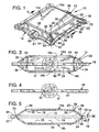
- FIG. 1 is a perspective view of a collapsible ink cartridge in accordance with one aspect of the invention.
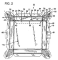
- FIG. 2 is a top plan view of the collapsible ink cartridge showing the ink cartridge in a collapsed configuration.
- FIG. 3 is a side elevational view of a collapsible ink cartridge.
- FIG. 4 is a side elevational view of a collapsible ink cartridge showing the ink cartridge in an empty, collapsed configuration.
- FIG. 5 is a cross-sectional view of a collapsible ink cartridge taken along line 5-5 of FIG. 1.
- FIG. 1 A collapsible ink cartridge in accordance with a preferred embodiment of the present invention is designated in FIG. 1 with reference numeral 10.
- the ink cartridge 10 includes a body 12 with two substantially identical opposing upper and lower wall panel assemblies 14a, 14b (see FIG. 3).
- the opposing wall panel assemblies 14a, 14b have opposed inner surfaces 15 (see FIG. 5).
- each of the panel assemblies 14a, 14b has a relatively large, square-shaped planar panel 16a, 16b.
- the square panels 16a, 16b respectively define the top and bottom of the cartridge 10.
- the panel assemblies 14a, 14b are joined at a square-shaped frame 18 and are, therefore, symmetrical about a central plane defined by the frame 18.
- the cartridge 10 in FIGS. 1 and 3 is shown in a maximum volume or full configuration.
- the upper and lower panel assemblies 14a, 14b extend respectively upward and downward from the frame 18 to define a cavity 19 within the body 12 for the storage of ink (see FIG. 5).
- the body 12 is collapsible to an empty configuration wherein the upper and lower panel assemblies 14a, 14b collapse flat against each other within a plane defined by the frame 18 (see FIGS. 2 and 4).
- the upper square panel 16a has four identical straight edges 20.
- the frame 18 has four substantially identical frame side members 22.
- the square panel 16a is positioned with respect to the frame 18 so that the square panel edges 20 align with the frame side members 22. Accordingly, the upper panel assembly 14a and the frame 18 have four sides of substantially common construction.
- One side of common construction is designated by reference numeral 23 and the phantom line of FIGS. 1 and 2. The description of this side 23 applies equally as well to the other three sides of common construction between the upper panel assembly 14a and frame 18.
- an elongate rectangular edge panel 24 interconnects the square panel 16a and an intermediate portion 26 of the frame side member 22.
- the rectangular edge panel 24 has inner and outer longitudinal edges 28, 30 and end edges 34.
- the edge panel longitudinal edges 28, 30 are substantially equal in length to the square panel edge 20.
- the edge panel inner edge 28 is hinged to the square panel edge 20 at a square panel hinge 35.
- the edge panel outer edge 30 is hinged to the frame intermediate portion 26 at a double hinge 36.
- the edge panels 24 of the symmetrical upper and lower panel assemblies 14a, 14b attach to the frame intermediate portion 26 at the double hinge 36 (see FIG. 5).
- the edge panel 24 extends diagonally between the upper square panel 16a and the frame 18 when the cartridge 10 is in the full configuration (see FIG. 3).
- the edge panel 24 lays flat with the square panel 16a within the plane defined by the frame 18 when the cartridge 10 is in the empty configuration (see FIG. 4).
- a triangular (corner) panel 39 is attached to each edge panel end edge 34 at an end hinge 40.
- FIG. 2 shows the panels of the first common side construction 23 flat, in the empty configuration. So viewed, the triangular panel 39 has one 45° angle, one obtuse angle, and one acute angle of less than 45°.
- the shortest (first) edge 42 of the triangle is defined between the 45° and obtuse angles.
- the longest (second) edge 44 of the triangle is defined between the 45° and acute angles.
- a third edge 46 of the triangle is defined between the acute and obtuse angles.
- the triangular panel first edge 42 is substantially equal in length to the edge panel end edge 34, and attaches thereto at end hinge 40.
- the second edge 44 of the triangular panel 39 extends radially outward from the corner of the upper square panel 16a. In other words, the line defined by the second triangular panel edge 44 diagonally bisects the upper square panel 16a.
- the diagonally bisecting lines defined by both triangular panel second edges 44 of the common side of construction 23 are mutually perpendicular so that the common side of construction 23 forms a 90° "slice" from the upper panel assembly 14a.
- the triangular panel third edge 46 extends outward from the edge panel outer edge 30.
- the third edge 46 is hinged to a frame corner portion 50 at a corner double hinge 52.
- the frame corner portion 50 is set apart from the frame intermediate portion 26 by an outwardly opening frame side notch 54 that aligns with the end hinge 40.
- the corner double hinge 52 is substantially identical in construction to frame double hinge 36.
- the corner double hinge 52 connects the symmetric triangular panels 39 of both the upper and lower panel assemblies 14a, 14b to the frame corner portion 50.
- the common side of construction 23 is integrally attached to adjacent common sides of construction at corner hinges 48.
- One corner hinge 48 hinges each triangular panel 39 of the common side of construction 23 to an identical triangular panel 39 of an adjacent common side of construction.
- Each hinged pair of triangular panels 39 attach to the corner hinge 48 at their second edges 44 and extend symmetrically therefrom.
- pairs of hinged triangular panels 39 are positioned at each corner of the upper panel assembly 14a.
- the pairs of triangular panels 39 project beyond the lines formed by the edge panel outer edges 30.
- the projection of the pairs of triangular panels 39 permits the edge panel outer edges 30 and the triangular panel third edges 46 to remain within the plane defined by the frame 18 in the full and the empty configurations (see FIGS. 1 and 4).
- the frame corner portions 50 of adjacent common sides of construction intersect at a corner notch 55.
- the corner hinges 48 extend radially from the corners of the upper wall panel 16a to the corner notches 55 at the corners of the frame 18.
- edge panels 24 extend diagonally at an angle of about 35° from the plane of the frame 18.
- the corner hinges 48 extend upwardly from the corners of the frame corner portions 50 to the corners of the upper square panels 16a.
- the triangular panels 39 of adjacent common sides of construction 23 angle downwardly on either side of the corner hinges 48 to the end hinges 40 and the double corner hinges 52.
- the material around the frame side and corner notches 54, 55 is resilient.
- the resilient material permits the frame 18 at the notches 54, 55 to resiliently flex during the collapse of the body 12 from the full configuration (FIG. 1) to the empty configuration (FIG. 2).
- the hinges 35, 40, 48 and double hinges 36, 52 flex to permit the inner surfaces 15 of the body 12 (see FIG. 5) to lie flat and smooth against each other in the collapsed empty configuration.
- FIG. 5 shows a cross-section of double hinge 36.
- the frame intermediate portion 26 and the edge panel outer edge 30 have opposing bevels that form an upper framing groove 59.
- An identical symmetric lower framing groove 60 is formed between the edge panel 24 of the lower panel assembly 14b and the frame intermediate portion 26.
- a bridge of the frame's resilient material separates the bottoms of the grooves 59, 60.
- the resilient material flexes to permit the edge panels 24 of the upper and lower panel assemblies 14a, 14b to pivot together about the frame double hinge 36.
- the corner double hinge 52 is of similar construction to permit the triangular panels 39 of the upper and lower panel assemblies 14a, 14b to pivot together.
- FIG. 5 shows a cross-section of an exemplary square panel hinge 35.
- the hinge 35 includes opposing bevels on the square panel edge 20 and the edge panel inner edge 38 to form a V-shaped hinge groove 56 on the exterior of the panel assembly 14a.
- a narrow bridge of resilient material remains between the bottom of the hinge groove 56 and the inner surface 15 of the panel assembly 14a.
- the panel assembly inner surface 15 is unbroken across the square panel hinge 35.
- the edge and corner hinges 40, 48 are of substantially identical construction.
- the panel assembly inner surface 15 is completely smooth and flat in the empty configuration.
- the hinges 35, 40, 48 are identical to the corresponding hinges of the symmetric lower panel assembly 14b.
- the inner surfaces 15 of both the upper and lower panel assemblies 14a, 14b are smooth and lie flat against each other in the empty configuration (see phantom in FIG. 5).
- the cartridge 10 is filled with ink in the full configuration.
- One frame intermediate portion 26 is shaped to define a fitment 61 with an orifice 62 through which ink may be conducted in and out of the cartridge (see FIG. 1).
- the fitment 61 may include a stopper, valve, or pierceable septum (not shown) to occlude the orifice until a tube or other coupler is inserted into the orifice for removing ink.
- the upper and lower panel assemblies 14a, 14b collapse toward each other to reduce the volume of the cavity 19.
- Fitment 61 may also be located on any of the flat planar surfaces as well.
- the edge panels 24 pivot about the double hinge 36 to lie flat within the plane of the frame 18.
- the hinges 35 flex as square panel 16a moves with the edge panel inner edge 38 inward toward the plane of frame 18.
- the end hinges 40 and corner hinges 48 flex as the triangular panels 39 pivot about the double corner hinges 52 to lie flat within the frame 18.
- the panels of the upper and lower panel assemblies 14a, 14b collapse at the same time and in the same way. Thus, each panel of the upper panel assembly 14a is always in vertical alignment with the matching panel of the symmetrical lower panel assembly 14b.
- Ink is drawn from the cartridge body 12 until the volume of cavity 19 is completely diminished in the empty configuration.
- the unbroken inner surfaces 15 of the upper and lower panel assemblies 14a, 14b lie flat and smooth against each other within the plane of the frame 18 (see phantom in FIG. 5). No voids remain within the body 12 in the empty configuration, so that essentially no ink is retained within the empty cartridge 10.
- the cartridge 10 is constructed so that the frame 18 resiliently flexes and expands (see phantom in FIG. 5) during the collapse of the body 12 from the full configuration to the empty configuration.
- the collapse of the edge panels 24 forces the frame intermediate portions 26 outwardly.
- the collapse of the triangular corner panels 39 forces the frame corner portions 50 to pivot open about the corner notches 55 (not shown). Thus, the notches 55 are partially closed.
- the frame side notches 54 resiliently open as the frame corner portions 50 and the frame intermediate portions 26 move outwardly.
- the cartridge 10 is preferably constructed to be biased toward the full configuration.
- the bias may be accomplished by fabricating the cartridge in the full configuration. As a result, the resilient material of each of the hinges and notches is relaxed when the cartridge 10 is in the full configuration. The resilient material becomes stressed as the cartridge 10 collapses into the empty configuration. The stresses bias the cartridge 10 back to the full configuration. The bias is sufficient to store the ink under a back pressure within the cavity.
- the bias is also advantageous in applications where the cartridge has a tube that is periodically coupled with the pen to refill the pen reservoir.
- the bias provides a sucking action when the tube is uncoupled from the pen after refilling. The sucking action prevents overfill of the pen by sucking away ink that is free within the pen, and prevents dripping by sucking the ink near the open end of the tube deeper into the tube.
- the elongate frame side members 22 may be longitudinally resilient to provide a bias of the cartridge 10 toward the full configuration.
- the side members 22 resiliently flex in tension as the body 12 collapses within the frame 18. The resilient tensile stretching biases the cartridge 10 toward the full configuration.
- an actuator may squeeze the upper and lower wall panels of the cartridge together to discharge ink into the pen. Upon completion of the pen refill, the actuator may be retracted a small amount so that the cartridge bias causes ink to be sucked back within the tube.
- the ink cartridge 10 is preferably constructed of a single material.
- the cartridge 10 may be composed of a single homogenous resin, such as high density polyethylene (HDPE).
- HDPE high density polyethylene
- a cartridge made of such a resin has resilient hinges and notches and relatively rigid panel sections. To provide the bias toward the full configuration, the cartridge 10 may be molded into the full configuration.
- the form of the full cartridge 10, as best shown in FIGS. 1 and 3, provides several advantages.
- the full cartridge 10 is relatively thin, with the flat upper and lower square panels 16a, 16b positioned respectively above and below the fitment 61.
- the full cartridges 10 are compactly stackable one on top of another without interference with the fitment 61.
- the cartridge 10 also serves as its own package.
- An opening 66 is formed in the frame intermediate portion 26 opposite the orifice 62 to permit the ink cartridge 10 to be hung on racks for retail display, or for storage.
- Tough cartridge materials such as HDPE provide protection against damage.
- the HDPE wall panels are thick enough to minimize ink loss due to ink diffusion through the cartridge body.
- materials such as HDPE permit product labelling to be molded directly into the cartridge panels.
- the construction of the cartridge from a single material facilitates the recycling of empty cartridges. Moreover, the very thin profile of an empty cartridge (see FIG. 4) is advantageous in minimizing the volume of recycled or discarded cartridges.
- Empty cartridges may be compactly stacked one on top of another if each consecutive cartridge 10 is rotated 90° from the previous cartridge in the stack. In this way, the fitment 61 of the stacked cartridges do not impinge on the fitment 61 of neighboring stacked cartridges.
- the construction of the illustrated embodiment may be altered in a variety of ways with equally good results.
- the cartridge may be formed in a variety of shapes, such as a triangle or any polygon.
- the shape and number of wall panels may be varied with equally good results.
- a smooth-membered frame may be provided that dispenses with the notches 54, 55. Such a notchless frame will suffice if sufficiently resilient to permit the outward movement of the individual panels of the collapsing body 12.
- HDPE is a preferred material for the cartridge 10, it is also to be understood that other materials, or combinations of materials, may work as well.
- the panel sections may be constructed of a stiff material, while the hinge and notch material is of a resilient material.
Applications Claiming Priority (2)
| Application Number | Priority Date | Filing Date | Title |
|---|---|---|---|
| US229047 | 1994-04-18 | ||
| US08/229,047 US5691755A (en) | 1994-04-18 | 1994-04-18 | Collapsible ink cartridge |
Publications (2)
| Publication Number | Publication Date |
|---|---|
| EP0678390A2 true EP0678390A2 (fr) | 1995-10-25 |
| EP0678390A3 EP0678390A3 (fr) | 1995-11-08 |
Family
ID=22859640
Family Applications (1)
| Application Number | Title | Priority Date | Filing Date |
|---|---|---|---|
| EP95302092A Withdrawn EP0678390A2 (fr) | 1994-04-18 | 1995-03-29 | Cartouche d'encre déformable |
Country Status (3)
| Country | Link |
|---|---|
| US (1) | US5691755A (fr) |
| EP (1) | EP0678390A2 (fr) |
| JP (1) | JP3723603B2 (fr) |
Cited By (5)
| Publication number | Priority date | Publication date | Assignee | Title |
|---|---|---|---|---|
| EP0863015A3 (fr) * | 1997-03-03 | 1998-12-02 | Hewlett-Packard Company | Système d'alimentation en encre |
| EP0899112A3 (fr) * | 1997-08-20 | 2000-05-17 | Brother Kogyo Kabushiki Kaisha | Imprimante par jet d'encre et réservoir d'encre utilisé dans cet imprimante |
| EP1053873A1 (fr) * | 1999-04-27 | 2000-11-22 | Canon Kabushiki Kaisha | Réservoir pour des liquides, système d'alimentation en liquide et procédé de fabrication du réservoir |
| EP2397336A1 (fr) * | 2010-06-17 | 2011-12-21 | Brother Kogyo Kabushiki Kaisha | Récipient de liquide, dispositif d'alimentation en liquide et appareil d'impression d'images |
| EP2110252A3 (fr) * | 2008-04-14 | 2012-04-04 | Ricoh Company, Ltd. | Récipient d'encre et appareil de formation d'images l'intégrant |
Families Citing this family (17)
| Publication number | Priority date | Publication date | Assignee | Title |
|---|---|---|---|---|
| USD425553S (en) * | 1998-04-09 | 2000-05-23 | Hewlett-Packard Company | Fluid container |
| AU132827S (en) * | 1997-03-03 | 1998-02-09 | Hewlett Packard Co | Ink cartridge for printers |
| US6068371A (en) * | 1997-09-22 | 2000-05-30 | Owens-Illinois Closure Inc. | Liquid containment and dispensing device with improved position indicating indicia |
| US6276787B1 (en) * | 1997-09-26 | 2001-08-21 | Brother Kogyo Kabushiki Kaisha | Ink supplying device |
| USD432567S (en) * | 1998-04-09 | 2000-10-24 | Hewlett-Packard Company | Fluid container |
| DE69935117T2 (de) * | 1998-12-24 | 2007-10-25 | Seiko Epson Corp. | Tintensack für Tintenstrahlaufzeichnungsgerät und Packung zum Verpacken eines solchen Sackes |
| USD427628S (en) * | 1999-07-01 | 2000-07-04 | Pitney Bowes Inc. | Ink cartridge |
| TW471394U (en) * | 1999-09-09 | 2002-01-01 | Wisertek Internat Corp | Structure for ink cartridge with negative pressure |
| US6364474B1 (en) * | 1999-09-10 | 2002-04-02 | Industrial Technology Research Institute | Pressure control device |
| US6609789B1 (en) | 2002-03-11 | 2003-08-26 | Banctec, Inc. | Ink cartridge |
| US20090273655A1 (en) * | 2004-12-29 | 2009-11-05 | Sj-D5 Inc. | Ink reservoir for inkjet print system |
| JP4806616B2 (ja) * | 2006-09-29 | 2011-11-02 | 富士フイルム株式会社 | インクカートリッジ及びインクジェット記録装置 |
| JP5455755B2 (ja) * | 2009-06-08 | 2014-03-26 | 株式会社セイコーアイ・インフォテック | インクジェット記録装置 |
| US9132648B2 (en) | 2014-02-19 | 2015-09-15 | Ricoh Company, Ltd. | Fluid cartridge label stiffener |
| JP6372369B2 (ja) * | 2014-03-31 | 2018-08-15 | ブラザー工業株式会社 | 液体収容体 |
| CN107953674B (zh) * | 2016-10-17 | 2020-11-06 | 精工爱普生株式会社 | 液体容纳体 |
| USD995625S1 (en) * | 2020-07-28 | 2023-08-15 | Keyence Corporation | Cartridge for continuous inkjet printer |
Citations (10)
| Publication number | Priority date | Publication date | Assignee | Title |
|---|---|---|---|---|
| US4422084A (en) * | 1979-11-06 | 1983-12-20 | Epson Corporation | Fluid tank and device for detecting remaining fluid |
| JPS62121062A (ja) * | 1985-11-21 | 1987-06-02 | Seiko Epson Corp | インクジエツトプリンタ用インクカ−トリツジの製造方法 |
| JPH01141752A (ja) * | 1987-11-30 | 1989-06-02 | Canon Inc | インクカートリッジ |
| JPH01141751A (ja) * | 1987-11-30 | 1989-06-02 | Canon Inc | インクカートリッジ |
| EP0437363A2 (fr) * | 1990-01-12 | 1991-07-17 | Hewlett-Packard Company | Accumulateur sensible à la pression pour imprimantes à jet d'encre |
| EP0490545A2 (fr) * | 1990-12-07 | 1992-06-17 | Canon Kabushiki Kaisha | Cartouche de tête à jet d'encre, cartouche de réservoir d'encre utilisant un matériau plastique dégradable comme élément de construction ou d'emballage et appareil à jet d'encre avec un élément de fixation pour les cartouches |
| EP0560398A2 (fr) * | 1992-03-13 | 1993-09-15 | Canon Kabushiki Kaisha | Réservoir d'encre |
| EP0604119A2 (fr) * | 1992-12-23 | 1994-06-29 | Hewlett-Packard Company | Cartouche à encre avec réservoir d'encre déformable |
| EP0604128A1 (fr) * | 1992-12-23 | 1994-06-29 | Hewlett-Packard Company | Cartouche d'imprimante à jet d'encre |
| EP0633137A2 (fr) * | 1993-06-30 | 1995-01-11 | Hewlett-Packard Company | Méthode de recharge pour cartouche d'impression par jet d'encre |
Family Cites Families (38)
| Publication number | Priority date | Publication date | Assignee | Title |
|---|---|---|---|---|
| US3438058A (en) * | 1967-08-18 | 1969-04-08 | Foxboro Co | Box pen inking system |
| JPS5812909B2 (ja) * | 1976-04-05 | 1983-03-10 | 三井化学株式会社 | 耐熱性ポリエステル組成物 |
| DE2804927A1 (de) * | 1978-02-06 | 1979-08-09 | Rotring Werke Riepe Kg | Schreibfluessigkeitspatrone oder -tank |
| US4272773A (en) * | 1979-05-24 | 1981-06-09 | Gould Inc. | Ink supply and filter for ink jet printing systems |
| US4429320A (en) * | 1979-09-21 | 1984-01-31 | Canon Kabushiki Kaisha | Ink jet recording apparatus |
| US4383263A (en) * | 1980-05-20 | 1983-05-10 | Canon Kabushiki Kaisha | Liquid ejecting apparatus having a suction mechanism |
| DE3137969A1 (de) * | 1981-09-24 | 1983-03-31 | Olympia Werke Ag, 2940 Wilhelmshaven | Kupplung zum leckfreien verbinden gas- oder fluessigkeitsgefuellter rohre und behaelter |
| JPS58131071A (ja) * | 1982-01-25 | 1983-08-04 | Konishiroku Photo Ind Co Ltd | インクジエツト記録装置 |
| US4432005A (en) * | 1982-05-10 | 1984-02-14 | Advanced Color Technology, Inc. | Ink control system for ink jet printer |
| US4480259A (en) * | 1982-07-30 | 1984-10-30 | Hewlett-Packard Company | Ink jet printer with bubble driven flexible membrane |
| US4509062A (en) * | 1982-11-23 | 1985-04-02 | Hewlett-Packard Company | Ink reservoir with essentially constant negative back pressure |
| US5126767A (en) * | 1984-02-09 | 1992-06-30 | Canon Kabushiki Kaisha | Ink tank with dual-member sealing closure |
| JPH0698774B2 (ja) * | 1984-02-09 | 1994-12-07 | キヤノン株式会社 | インク容器 |
| JPS60204366A (ja) * | 1984-03-30 | 1985-10-15 | Canon Inc | インクジエツト記録ヘツドおよびその保存方法 |
| JPS61277460A (ja) * | 1985-06-04 | 1986-12-08 | Ricoh Co Ltd | インクジエツト記録装置のインク容器 |
| US4677447A (en) * | 1986-03-20 | 1987-06-30 | Hewlett-Packard Company | Ink jet printhead having a preloaded check valve |
| US4771295B1 (en) * | 1986-07-01 | 1995-08-01 | Hewlett Packard Co | Thermal ink jet pen body construction having improved ink storage and feed capability |
| US4790361A (en) * | 1986-07-25 | 1988-12-13 | Containers Unlimited | Collapsible carbonated beverage container |
| JPH0751687B2 (ja) * | 1986-09-05 | 1995-06-05 | セイコーエプソン株式会社 | 記録用インク |
| US4714937A (en) * | 1986-10-02 | 1987-12-22 | Hewlett-Packard Company | Ink delivery system |
| CA1299553C (fr) * | 1987-03-11 | 1992-04-28 | Ruben Nevarez | Methode et dispositif d'amorcage pour plume a jet d'encre |
| US4920362A (en) * | 1988-12-16 | 1990-04-24 | Hewlett-Packard Company | Volumetrically efficient ink jet pen capable of extreme altitude and temperature excursions |
| US4961076A (en) * | 1987-10-28 | 1990-10-02 | Hewlett-Packard Company | Reliability improvement for ink jet pens |
| US4794409A (en) * | 1987-12-03 | 1988-12-27 | Hewlett-Packard Company | Ink jet pen having improved ink storage and distribution capabilities |
| US4831389A (en) * | 1987-12-21 | 1989-05-16 | Hewlett-Packard Company | Off board ink supply system and process for operating an ink jet printer |
| US4992802A (en) * | 1988-12-22 | 1991-02-12 | Hewlett-Packard Company | Method and apparatus for extending the environmental operating range of an ink jet print cartridge |
| US4959667A (en) * | 1989-02-14 | 1990-09-25 | Hewlett-Packard Company | Refillable ink bag |
| US4935751A (en) * | 1989-09-21 | 1990-06-19 | Hewlett-Packard Company | Level sensor for ink bag |
| US5010354A (en) * | 1989-11-28 | 1991-04-23 | Hewlett-Packard Company | Ink jet pen with improved volumetric efficiency |
| US5040002A (en) * | 1990-03-16 | 1991-08-13 | Hewlett-Packard Company | Regulator for ink-jet pens |
| US5040001A (en) * | 1990-06-27 | 1991-08-13 | Hewlett-Packard Company | Collapsible storage bladder for ink cartridges |
| US5153612A (en) * | 1991-01-03 | 1992-10-06 | Hewlett-Packard Company | Ink delivery system for an ink-jet pen |
| EP0496620B1 (fr) * | 1991-01-25 | 1996-04-10 | Canon Kabushiki Kaisha | Appareil d'enregistrement à jet d'encre et cartouche à encre pour cet appareil |
| US5113199A (en) * | 1991-03-11 | 1992-05-12 | Hewlett-Packard Company | Ink delivery system for ink jet printers |
| US5185614A (en) * | 1991-04-17 | 1993-02-09 | Hewlett-Packard Company | Priming apparatus and process for multi-color ink-jet pens |
| US5187498A (en) * | 1991-07-24 | 1993-02-16 | Xerox Corporation | Ink supply container and system |
| US5146243A (en) * | 1991-07-29 | 1992-09-08 | Hewlett-Packard Company | Diaphragm cap system for ink-jet printers |
| US5574489A (en) * | 1994-03-30 | 1996-11-12 | Hewlett-Packard Company | Ink cartridge system for ink-jet printer |
-
1994
- 1994-04-18 US US08/229,047 patent/US5691755A/en not_active Expired - Lifetime
-
1995
- 1995-03-29 EP EP95302092A patent/EP0678390A2/fr not_active Withdrawn
- 1995-04-17 JP JP11505495A patent/JP3723603B2/ja not_active Expired - Fee Related
Patent Citations (10)
| Publication number | Priority date | Publication date | Assignee | Title |
|---|---|---|---|---|
| US4422084A (en) * | 1979-11-06 | 1983-12-20 | Epson Corporation | Fluid tank and device for detecting remaining fluid |
| JPS62121062A (ja) * | 1985-11-21 | 1987-06-02 | Seiko Epson Corp | インクジエツトプリンタ用インクカ−トリツジの製造方法 |
| JPH01141752A (ja) * | 1987-11-30 | 1989-06-02 | Canon Inc | インクカートリッジ |
| JPH01141751A (ja) * | 1987-11-30 | 1989-06-02 | Canon Inc | インクカートリッジ |
| EP0437363A2 (fr) * | 1990-01-12 | 1991-07-17 | Hewlett-Packard Company | Accumulateur sensible à la pression pour imprimantes à jet d'encre |
| EP0490545A2 (fr) * | 1990-12-07 | 1992-06-17 | Canon Kabushiki Kaisha | Cartouche de tête à jet d'encre, cartouche de réservoir d'encre utilisant un matériau plastique dégradable comme élément de construction ou d'emballage et appareil à jet d'encre avec un élément de fixation pour les cartouches |
| EP0560398A2 (fr) * | 1992-03-13 | 1993-09-15 | Canon Kabushiki Kaisha | Réservoir d'encre |
| EP0604119A2 (fr) * | 1992-12-23 | 1994-06-29 | Hewlett-Packard Company | Cartouche à encre avec réservoir d'encre déformable |
| EP0604128A1 (fr) * | 1992-12-23 | 1994-06-29 | Hewlett-Packard Company | Cartouche d'imprimante à jet d'encre |
| EP0633137A2 (fr) * | 1993-06-30 | 1995-01-11 | Hewlett-Packard Company | Méthode de recharge pour cartouche d'impression par jet d'encre |
Non-Patent Citations (3)
| Title |
|---|
| PATENT ABSTRACTS OF JAPAN vol. 11, no. 339 (M-639) (2786) 6 November 1987 & JP-A-62 121 062 (SEIKO) 2 June 1987 * |
| PATENT ABSTRACTS OF JAPAN vol. 13, no. 398 (M-866) (3746) 5 September 1989 & JP-A-01 141 751 (CANON) 2 June 1989 * |
| PATENT ABSTRACTS OF JAPAN vol. 13, no. 398 (M-866) (3746) 5 September 1989 & JP-A-01 141 752 (CANON) 2 June 1989 * |
Cited By (10)
| Publication number | Priority date | Publication date | Assignee | Title |
|---|---|---|---|---|
| EP0863015A3 (fr) * | 1997-03-03 | 1998-12-02 | Hewlett-Packard Company | Système d'alimentation en encre |
| EP0899112A3 (fr) * | 1997-08-20 | 2000-05-17 | Brother Kogyo Kabushiki Kaisha | Imprimante par jet d'encre et réservoir d'encre utilisé dans cet imprimante |
| US6227662B1 (en) | 1997-08-20 | 2001-05-08 | Brother Kogyo Kabushiki Kaisha | Ink jet printer and ink container used therein |
| EP1053873A1 (fr) * | 1999-04-27 | 2000-11-22 | Canon Kabushiki Kaisha | Réservoir pour des liquides, système d'alimentation en liquide et procédé de fabrication du réservoir |
| US6347865B1 (en) | 1999-04-27 | 2002-02-19 | Canon Kabushiki Kaisha | Liquid container, liquid supply system, and method for manufacturing such liquid container |
| EP2110252A3 (fr) * | 2008-04-14 | 2012-04-04 | Ricoh Company, Ltd. | Récipient d'encre et appareil de formation d'images l'intégrant |
| US8197045B2 (en) | 2008-04-14 | 2012-06-12 | Ricoh Company, Ltd. | Ink container comprising an ink pack and image forming apparatus incorporating the ink container |
| EP2397336A1 (fr) * | 2010-06-17 | 2011-12-21 | Brother Kogyo Kabushiki Kaisha | Récipient de liquide, dispositif d'alimentation en liquide et appareil d'impression d'images |
| CN102285237A (zh) * | 2010-06-17 | 2011-12-21 | 兄弟工业株式会社 | 液体容器、供液装置和图像打印设备 |
| CN102285237B (zh) * | 2010-06-17 | 2014-12-03 | 兄弟工业株式会社 | 液体容器、供液装置和图像打印设备 |
Also Published As
| Publication number | Publication date |
|---|---|
| EP0678390A3 (fr) | 1995-11-08 |
| US5691755A (en) | 1997-11-25 |
| JPH0885217A (ja) | 1996-04-02 |
| JP3723603B2 (ja) | 2005-12-07 |
Similar Documents
| Publication | Publication Date | Title |
|---|---|---|
| US5691755A (en) | Collapsible ink cartridge | |
| US8672183B2 (en) | Collapsible bottle and cover | |
| DE69834094T2 (de) | Flüssigkeitsversorgungsverfahren, Vorrichtung und Tintenstrahlpatrone verwendbar mit einer solchen Vorrichtung | |
| EP1044815A2 (fr) | Réservoir de liquide, tête d'enregistrement et appareil d'enregistrement l'utilisant | |
| AU720342B2 (en) | Ink jet printhead cartridge | |
| US20140146113A1 (en) | Liquid container and liquid ejection system | |
| US20180104955A1 (en) | Liquid container | |
| CN104029483B (zh) | 图像形成系统 | |
| JP2019085112A (ja) | インク収容ボトル | |
| US10974512B2 (en) | Ink replenishing container and ink replenishing system | |
| JP4207217B2 (ja) | 印刷装置 | |
| CN111469559A (zh) | 墨水补充容器和墨水补充系统 | |
| JP3803996B2 (ja) | 注出栓付き詰替え袋の収納ケース | |
| US6036306A (en) | Ink cartridge | |
| US5636760A (en) | Container for fluid | |
| US6312119B1 (en) | Method and apparatus for foam removal in an ink container | |
| US20060175343A1 (en) | Label tag dispenser | |
| US20220363066A1 (en) | Liquid storage container, method of manufacturing liquid storage container, and liquid ejecting apparatus | |
| US20230256744A1 (en) | Inkjet printer | |
| KR101161324B1 (ko) | 에어 펌프 디스펜서 | |
| EP3939793A1 (fr) | Conteneur de stockage de liquides | |
| US10780704B2 (en) | Ink-jet print head assemblies with a spacer surrounding an ink fill port and method of manufacturing | |
| JPH07171968A (ja) | インク容器 | |
| EP3445588B1 (fr) | Cartouche et imprimante | |
| US20030111377A1 (en) | Sheet dispenser carton with support member |
Legal Events
| Date | Code | Title | Description |
|---|---|---|---|
| PUAI | Public reference made under article 153(3) epc to a published international application that has entered the european phase |
Free format text: ORIGINAL CODE: 0009012 |
|
| PUAL | Search report despatched |
Free format text: ORIGINAL CODE: 0009013 |
|
| AK | Designated contracting states |
Kind code of ref document: A2 Designated state(s): DE FR GB IT |
|
| AK | Designated contracting states |
Kind code of ref document: A3 Designated state(s): DE FR GB IT |
|
| 17P | Request for examination filed |
Effective date: 19960131 |
|
| 17Q | First examination report despatched |
Effective date: 19960603 |
|
| STAA | Information on the status of an ep patent application or granted ep patent |
Free format text: STATUS: THE APPLICATION IS DEEMED TO BE WITHDRAWN |
|
| 18D | Application deemed to be withdrawn |
Effective date: 19971222 |