EP0677962B1 - Peripheral unit for satellite multi-videoconferencing - Google Patents
Peripheral unit for satellite multi-videoconferencing Download PDFInfo
- Publication number
- EP0677962B1 EP0677962B1 EP95105538A EP95105538A EP0677962B1 EP 0677962 B1 EP0677962 B1 EP 0677962B1 EP 95105538 A EP95105538 A EP 95105538A EP 95105538 A EP95105538 A EP 95105538A EP 0677962 B1 EP0677962 B1 EP 0677962B1
- Authority
- EP
- European Patent Office
- Prior art keywords
- block
- flow
- signal
- parallel
- series
- Prior art date
- Legal status (The legal status is an assumption and is not a legal conclusion. Google has not performed a legal analysis and makes no representation as to the accuracy of the status listed.)
- Expired - Lifetime
Links
- 230000002093 peripheral effect Effects 0.000 title claims description 24
- 230000005236 sound signal Effects 0.000 claims description 11
- 230000005540 biological transmission Effects 0.000 claims description 9
- 239000000284 extract Substances 0.000 claims description 9
- 230000011664 signaling Effects 0.000 claims description 8
- 102100040999 Catechol O-methyltransferase Human genes 0.000 claims description 5
- 108020002739 Catechol O-methyltransferase Proteins 0.000 claims description 5
- 238000012545 processing Methods 0.000 claims description 4
- 230000001934 delay Effects 0.000 claims description 2
- 230000000737 periodic effect Effects 0.000 claims description 2
- 238000012795 verification Methods 0.000 claims description 2
- 238000000034 method Methods 0.000 description 11
- 238000010586 diagram Methods 0.000 description 9
- 230000006870 function Effects 0.000 description 8
- 230000001360 synchronised effect Effects 0.000 description 5
- 238000009434 installation Methods 0.000 description 3
- 239000000969 carrier Substances 0.000 description 2
- 238000004891 communication Methods 0.000 description 2
- 238000000605 extraction Methods 0.000 description 2
- 230000001755 vocal effect Effects 0.000 description 2
- 230000004913 activation Effects 0.000 description 1
- 230000003111 delayed effect Effects 0.000 description 1
- 238000006073 displacement reaction Methods 0.000 description 1
- 238000002592 echocardiography Methods 0.000 description 1
- 230000002452 interceptive effect Effects 0.000 description 1
- 238000012986 modification Methods 0.000 description 1
- 230000004048 modification Effects 0.000 description 1
- 238000002360 preparation method Methods 0.000 description 1
- 230000001131 transforming effect Effects 0.000 description 1
- 230000001052 transient effect Effects 0.000 description 1
- 230000000007 visual effect Effects 0.000 description 1
- 239000002699 waste material Substances 0.000 description 1
Images
Classifications
-
- H—ELECTRICITY
- H04—ELECTRIC COMMUNICATION TECHNIQUE
- H04N—PICTORIAL COMMUNICATION, e.g. TELEVISION
- H04N7/00—Television systems
- H04N7/14—Systems for two-way working
- H04N7/15—Conference systems
Definitions
- the invention described herein relates to telecommunications systems for video, audio, and data information, and in particular it concerns a peripheral unit for satellite multi-videoconferencing.
- Multi-videoconferencing is a service that permits to connect with each other three or more conference rooms, allowing a video, voice and data connection between all people participating in the session present in the rooms.
- Working groups belonging to several offices, physically separated even by great distances, can thus conduct technical meetings with no need to go on expensive trips.
- the service is offered by still using the rooms and the equipment designed to carry out point-to-point videoconferencing, in which only two rooms are connected with each other so as to be mutually visible, thus simulating what occurs in a meeting between two groups seated at opposite sides of a table.
- the rooms are equipped with a meeting table, on one side of which local participants are seated, who come in contact with the participants present in the remote room by receiving their images through monitors present on the other side of the table.
- the room equipment is thus designed to collect video, voice and data information generated locally, and, through a CODEC, to encode it so as to conveniently transmit it to the room where it is decoded and displayed in real time.
- each room is in contact with two or more other rooms.
- Room equipment is generally not dimensioned to do this, both in terms of visual displays and in terms of decoding equipment, as both can normally process the flow coming from just a single connection. In any case, even if it were possible, the resulting performance would risk becoming irksome with the increase in number of rooms simultaneously connected.
- the multi-videoconferencing service is carried out by collecting in real time the video coming from each room and sending, to each room, only the image it is interested in.
- the adopted strategy for selecting the image of interest is as follows:
- the rooms involved are connected in a star configuration to a national centre, where there is a control unit that carries out the dynamic routing operations required throughout the network.
- a satellite link is already used to interconnect the national control unit with the one located with the operator of the network to which the rooms to be reached are connected.
- Videoconferencing rooms may be permanently installed at private user's or at the public operator's locations, and the latter may also offer a temporary installation where there is no actual need justifying setting up a permanent room and when the customer, for the sake of logistics, of his image, or for other reasons, is not willing to use a public room.
- the operator offers to temporarily set up the room at the customer's site, by utilizing a transportable module which includes all necessary audio and video equipment, as well as signal encoding and decoding equipment.
- a satellite link attained through transportable stations allocated for the occasion to the temporary room, is usually employed.
- a point-to-point video-conference has to be conducted, then the transportable stations are linked directly to the two rooms involved and the connection takes place via satellite. Similarly, if a multi-video-conference where only one temporary room is present has to be performed, then the latter is linked via satellite to the control center, to which the other rooms are connected through a ground network.
- the control unit receives the information flow, typically at the bit rate of 2 Mbit/s, coming from each room, decodes it extracting the video, audio, data and signalling components, and then reconstructs the flows to send to each room.
- the video and data selected are organized according to one of the previously described techniques, while the voice signal, in order to introduce no echoes, is the signal obtained from the sum of all those coming from all the other rooms. This technique allows each room to have the feeling of what is occurring in all the others, though they are not visible.
- the signal reaches its destination after a single transit through the satellite and at any given time only 2 video channels are occupied, regardless of the number of rooms taking part in the same multi-video-conference, allowing a remarkable bandwidth saving.
- a 64 Kbit/s bi-directional channel is utilized in addition to the two video channels.
- the system comprises a number of peripheral multi-videoconferencing units equal to the number of interconnected rooms, and a direction unit.
- the peripheral units according to the present invention are tasked with interfacing room CODECs with the satellite network, whilst the direction unit controls and manages the network, which is thus dynamically reconfigured in real time.
- peripheral units are connected in a star configuration to the direction unit by means of the same number of 64Kbit/s bi-directional channels which, as previously stated, carry the network signalling and the audio from the rooms.
- the peripheral unit for satellite multi-videoconferencing allows building a multi-videoconferencing system that, by fully exploiting the features of the satellite medium, can be used to provide the service even to users that are not linked to the ground network.
- the system allows a connection between several remote rooms through a satellite network, interfaceable with a ground control centre, to build an overall mixed ground-satellite network that is able to simultaneously serve both permanent and temporary users, extending the potential number of customers.
- Particular object of the present invention is to provide a peripheral unit for satellite multi-videoconferencing as described in the characterizing portion of claim 1.
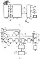
- a peripheral installation for satellite multi-videoconferencing is shown in Figure 1. It is composed of a peripheral unit MVC, a video encoder and decoder CODEC, one or more video cameras TC, one or more monitors MO, microphones MI to be used by the participants, loudspeakers AP, a control mini-console MC and a portable transceiving station ST, provided with antenna AN, for the satellite link.
- the portable station is connected to peripheral unit MVC by means of two 2 Mbit/s bi-directional links TXA, RXA and TXB, RXB relevant to the video and audio signals of the current speaker and of the previous speaker, and by means of a 64 Kbit/s bi-directional link COMT, COMR relevant to the signalling and to a service audio signal.
- a wire CO for controlling the switching between the signal relevant to the current speaker and the one relevant to the previous speaker and the activation of the transmission by station ST.
- the peripheral unit is connected to the video CODEC through the opposite direction links IN and OU.
- the 2 Mbit/s flows transiting over these links are structured in accordance with network standard G704, apt to carry a signal that is in accordance with standard CCITT H221.
- Peripheral unit MVC carries out the following tasks:
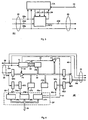
- peripheral unit MVC The block diagram of peripheral unit MVC is shown in Figure 2.
- Unit MVC is subdivided into two logically separated and time-independent parts, one utilized to process data coming from the portable station and directed toward the CODEC and the other one utilized for the opposite path, i.e. from the CODEC to the portable station.
- Interfaces IFC and IFR comprise sections RX1, 2, 3 and TX1, 2, 3 that are in accordance with standard G704.
- Sections TXI, 2, 3 receive separate data and clock signals and encode them so as to allow their transmission over a single wire at the bit rate of 2 Mbit/s, inserting frame synchronism information, allocated in time slot 0.
- Sections RX1, 2, 3 perform the opposite operation, which consists of extracting from the single input signal the data, the 2 MHz clock signal and the frame synchronism with a period of 125 ⁇ s.
- Interface IFS implements RS422 standard, by transforming the data and the clock signal from balanced to unbalanced signals and viceversa.
- Block EF extracts from the data flow the flow present in time slot 1, converts it to a bit rate of 64 Kbit/s and transmits it by means of connection 20 to interface IFS. This latter transforms it in accordance with standard RS422 and sends it through connection COMT to a transmission modem contained in the portable station. EF, moreover, inserts and extracts the service audio signal exchanged between local operator and operator in the direction unit.
- connection COMR The equivalent 64 Kbit/s channel, coming from the station over connection COMR, is passed through the same interface IFS to a block GP by means of connection 28.
- the entire data flow is also transferred to the two sections TX 1 and TX2 of interface IFR to construct the two carriers TXA and TXB.
- This latter block consists of a buffer for the alignment of the G704 frame.
- the flow selected by the multiplexer has a timing associated with the source, in order to be manipulated by the logic contained in subsequent blocks it must be synchronized with the internal timing of the latter, provided though wire 22 by a block AF.
- Block BU performs this function guaranteeing the same timing of the outgoing flow even when switching between one source and another one.
- the data in output from BU over connection 23 then transit through aforesaid block AF.
- This latter has the task of manipulating and structuring information useful to block GP, able to manage protocol H221, with which it is interconnected by means of bi-directional connections 24 and 25.
- BM a further functional block, consisting essentially of a buffer, whose task is to perform the alignment of the multi- frame before sending it over wire 56 to section TX3 of interface IFC toward the video CODEC.
- This latter buffer prevents the discontinuity of protocol H221 toward the CODEC, which occurs when MX executes a switching between different data sources, generally not synchronized with each other either at frame or at multi-frame level.
- Possible phase displacements are recovered in output by buffer BM with the joint help of a microprocessor MCP, able to perform peripheral control through connection 19.
- time slot 0 is re-generated by a block TSO and inserted into the frame by section TX3 of interface IFC.
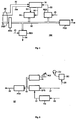
- Block BU is represented in further detail in the block diagram of Figure 3.
- the serial data, the frame synchronism signal and the clock signal arrive through connection 29 by utilizing respectively wires 29d, 29s and 29c.
- the alignment function between incoming data and the local frame synchronism, coming from block AF through wire 22, is performed by means of a logic circuit CA and of a First-In First-Out memory FIFO, into which the serial data and the relative frame synchronism signal, time associated to the data, are separately written.
- Logic circuit CA providing all command signals to the FIFO, is able to perform the following logic operations:
- logic circuit CA The procedure carried out by logic circuit CA is the following.
- circuit CA remains waiting for the arrival, over wire 29s, of the synchronism signal; when this latter appears, FIFO writing is enabled.
- This operation allows guaranteeing that the first cell of the FIFO will contain the first bit of data of the frame and the relevant associated synchronism.
- the procedure remains waiting for the local frame synchronism signal over wire 22, while the memory continues its data memorization phase.
- CA enables FIFO reading, thus performing the desired alignment between data read and local synchronism.
- the alignment check is structured into two steps: the first is to wait for the local synchronism signal, whilst the second is to verify that, simultaneously with this latter, the synchronism associated with data read from the FIFO through connection 34 is also present.
- a logic circuit able to execute this procedure can easily be made by utilizing programmable logic components.
- the 2 Mbit/s serial data flow present at the input over wire 23d, is split into two flows, which are simultaneously sent to two series-to-parallel converters SP1 and SP2, which extract the serial flows respectively from time slot 1 and from time slots 2,..., 31 and provide them to their outputs with 8 bit parallelism.
- the parallel flow in output from SP1 is transferred to a parallel-to-series converter PSI to be converted into a serial flow at the bit rate of 64 Kbit/s, which is then made available over wire 24a, connected to block GP.
- This last block is composed of three blocks, dedicated to processing the protocol H221, in particular a transmission block HTI and two reception blocks HR1 and HR2.
- Integrated components including both the receiving part and the transmitting part of the H221 protocol manager are well known: an example is the one described in United States Patent no. 5.197.083, by the same applicant.
- Block HR2 extracts from the 64 kbit/s flow, which it receives over connection 28 from interface IFS ( Figure 2), information relevant to the management of the multi-videoconferencing network coming in from the centralized direction.
- Block HR1 extracts from the 64 kbit/s flow information relevant to the H221 protocol, in particular signalling information between the systems for encoding and decoding the room image and audio signal.
- HR1 simultaneously loads time slot 1 of the n-th frame and gives back at the output, over wire 24b, time slot 1 of the (n-1)th frame, which is in turn transferred into a series-to-parallel converter SP3 to be memorized into a delay buffer memory ME.
- This memory of 8 kbyte capacity, is capable of memorizing 164 G704 frames and can be reached through connection 40.
- Signalling information is made available through connection 19 to microprocessor MCP ( Figure 2), which sends the required commands to the local CODEC.
- the sample of time slot I is read and, through connection 40, sent to a parallel-to-series converter PS2 to be converted into a serial flow at a bit rate of 64 Kbit/s, which is then made available over wire 25a, connected to block GP.
- the serial flow transits through transmitting block HT1 of the manager of the H221 protocol and, at the subsequent frame, is sent by means of wire 25b to a series-to-parallel converter SP4.
- the overall delay that a sample of time slot 1 undergoes from the time it is emitted by HRI to the time it is received by HTI is equal to 160 frames (1 in SP3, 158 in ME and 1 in PS2). Such delay is necessary to allow extraction of a complete message by HR1 and its forwarding to the microprocessor through connection 19, so that the latter can process it and obtain the appropriate command to send to HT1. While, transiting through GP, the message brought by the serial flow must be suitably modified by the microprocessor.
- a further task of block HT1 is to insert H221 frame synchronisms under microprocessor MCP control ( Figure 2), so as to guarantee protocol continuity even in the absence of a valid input signal.
- the other flow with 8 bit parallelism, provided by SP2, is transferred from a port P1 in the intervals assigned to time slots 2,..., 31 over connection 40 to be memorized in memory ME.
- Each sample belonging to time slots 2,..., 31 is read 164 frames after being written, whilst, as previously seen, the sample belonging to time slot 1 is delayed by 158 frames in ME.
- the one-frame delays undergone in blocks PS1, HR1, SP3, PS2, HT1, and SP4 are added, the sample belonging to time slot 1, too, undergoes an overall delay of 164 frames.
- the transmitting block HT1 of the H221 protocol manager also provides over a wire 41 an H221 frame-start synchronism signal, which will be inserted from a port P2 over connection 40 in correspondence with time slot 0, which is free, as the frame synchronism information had already been used by the previous block BU ( Figure 2).
- an H221 frame-start synchronism signal which will be inserted from a port P2 over connection 40 in correspondence with time slot 0, which is free, as the frame synchronism information had already been used by the previous block BU ( Figure 2).
- the whole circuit is timed by block TI, which, on the basis of the clock signal present over wire 29c, generates the reading and writing addresses, made up of a common 5 bit part, present over connection 42, which represents the channel number, and of two 8 bit parts with 158 or 164 module, present alternately over connection 43, which are utilized in correspondence with time slot 1 or time slots 2, ..., 31.
- the writing and reading cycles are organized, with respect to the time of stability of the addresses, in the following way: the reading cycle precedes the writing cycle of the same cell, where a sample of the channel is memorized, to guarantee an input-output delay equal to 164 frames.
- Block TI furthermore generates: over wire 44, signal active in correspondence with time slots 2, ..., 31; over wire 45, signal active in correspondence with time slots 0; over wire 46, signal active in correspondence with time slots 1; and over wire 22 frame timing signal, used also by block BU ( Figure 3), already described.
- Functional block BM whose task is to perform the multi-frame alignment, is represented in detail in Figure 5.
- Block BM with the help of microprocessor MCP ( Figure 2), guarantees the continuity of the protocol at multi-frame level during switching operations between the 2 Mbit/s flows coming from the portable station.
- a buffer memory BA is envisaged, with a capacity of 8 kbyte, able to memorize two H221 frames, or 160 G704 frames, from the 2 Mbit/s flow coming in over connection 26a.
- a timing block TE generates the writing and reading addresses for memory BA. These addresses are composed of a common 5 bit part, present over connection 51, which represents the channel number and is synchronized by the frame synchronism signal coming from block AF ( Figure 4) over wire 22, and of two 8 bit parts with module 160, alternately present over a connection 52, which are utilized in reading and writing.
- the read frame address scans the memory in a cyclical way with no external synchronization, while the written frame address is synchronized by a signal extracted from the 2 Mbit/s flow during time slot 0 by a register RE5 and provided over a connection 53.
- This signal is provided by block GP ( Figure 4) during frame 0 of protocol H221 and its function is to guarantee that the protocol itself is memorized starting from the beginning of the buffer memory.
- the protocol synchronism being written in memory as well, can in tum be extracted after the delay introduced by buffer memory BA and sent through a register RE4 and wire 55 to the microprocessor for the control functions.
- Register RE4 is enabled over wire 45 by the signal active in correspondence with time slot 0.
- data over connection 50 are converted into a fully serial 2 Mbit/s flow by a parallel-to-series converter PS3 and made available over wire 56.
- the block diagram in Figure 6 represents block EF, which extracts, from the data flow coming in from the video CODEC, the data flow transported in time slot 1 and transforms it into a 64 Kbit/s flow to be sent to the modem of the portable station for use by the direction centre to control the system.
- a series-to-parallel converter SP5 enabled by the signal over a wire 61, extracts the content of time slot 1 from the Mbit/s flow over a wire of connection 21, making it available in parallel form over a connection 62.
- the service audio signal transmitted by the local operator toward the direction unit, is also inserted.
- the audio signal collected by a microphone MOF which is the microphone used by the local operator, is converted into a digital signal by block IA and placed over connection 62.
- a subsequent parallel-to-series converter PS4 converts the parallel flow into a serial flow at the bitrate of 64 Kbit/s, which is then sent to interface IFS ( Figure 2) through a wire of connection 20.
- the signal over wire 61 is signal active in correspondence with time slot 1 and it is generated by a timing block TG, which, by utilizing a counter and a decoder, identifies the time allocation of time slot I within the serial flow.
- Block TG receives the frame synchronism with a period of 125 ⁇ s over wire 60 from interface IFC ( Figure 2).
- Block EC receives from connection 28 the digital audio signal coming from the operator in the direction unit and converts it so as to drive an acoustic headset CU for the local operator.
- Block MCP represented in Figure 2, is, as previously stated, a microprocessor suitably programmed to perform the following tasks:
Landscapes
- Engineering & Computer Science (AREA)
- Multimedia (AREA)
- Signal Processing (AREA)
- Radio Relay Systems (AREA)
- Two-Way Televisions, Distribution Of Moving Picture Or The Like (AREA)
- Data Exchanges In Wide-Area Networks (AREA)
- Superconductors And Manufacturing Methods Therefor (AREA)
- Engine Equipment That Uses Special Cycles (AREA)
- Catalysts (AREA)
Description
- all rooms are sent the image coming from the room where the current speaker is present, on the assumption that in any meeting speakers alternate, taking the floor one at a time, and in each moment everyone's attention is focussed on whoever is speaking;
- the current speaker's room is sent video coming from the room where the last person to speak before him is present, assuming that in general the current speaker takes the floor after an invitation by the previous speaker and therefore his intervention is directed mostly to the latter.
- the signal coming from the current speaker's room transits through the satellite, reaches the control unit, and from this it is once again sent to the other rooms through another satellite link. This involves a double jump which introduces an unacceptable delay on the signal, violating CCITT Recommendations regarding the admissible delay for interactive video and voice services;
- a number of couples of 2 Mbit/s channels equal to the number of connected rooms simultaneously transit through the satellite. This entails a large waste of resources, since, as seen previously, at any time only two links are actually utilized, i. e. the one for the current speaker and the one for the previous speaker.
- Figure 1 is a schematic view of a peripheral installation for satellite multi-videoconferencing;
- Figure 2 is a block diagram of the peripheral unit, denoted by MVC in Figure 1;
- Figure 3 is a block diagram of the block denoted by BU in Figure 2;
- Figure 4 is a block diagram of the blocks denoted by AF and GP in Figure 2;
- Figure 5 is a block diagram of the block denoted by BM in Figure 2;
- Figure 6 is a block diagram of the block denoted by EF in Figure 2.
- routing to the satellite the 2 Mbit/s flow coming from the CODEC over channel TXA or TXB, according to the indication of the direction unit;
- extracting from the 2 Mbit/s flow, coming from the CODEC over the link IN, the 64
Kbit/s flow present in
time slot 1 and relevant to the I-Channel of protocol H221, and sending this flow to the direction unit by means of link COMT; - selecting the 2 Mbit/s flow RXA or RXB, coming respectively from the current speaker or the previous speaker, to be sent to the CODEC through the link OU, upon indication of the direction unit;
- maintaining alignment of H221 frame and multi-frame on the flow sent to the CODEC, even in the absence of incoming flow or after switching of the flow source;
- inserting, into the flow toward the CODEC, the signalling prescribed by recommendation H230 for management of the multi-videoconferencing;
- managing local switchings, upon selection by the local operator, without being slaved to the direction unit during the network preparation phase;
- managing the service audio channel, which links operators located at the peripheral rooms with the operator in the direction unit, through links COMT and COMR, by utilizing the band not occupied by the signalling.
- initial synchronization between input and output data;
- periodic verification of whether alignment is maintained;
- check of out-of-alignment conditions;
- data re-synchronization.
- controlling access to the satellite by the peripheral unit through command line CO as a function of commands received from the direction and/or the local operator;
- selecting through block MX the channel to send to the local CODEC as a function of the commands received from the direction and/or the local operator;
- controlling blocks BU, HTI (Figure 4) and BM so as to guarantee the continuity of the H221 synchronization channel in the 2 Mbit/s output flow, even in the presence of discontinuities of the input flow, due both to source variation and to a temporary loss of the satellite link;
- generating H221 commands to insert through block HT1 into the 2 Mbit/s output flow.
Claims (5)
- Peripheral unit (MVC) for satellite multi-videoconferencing connected to a transceiving station (ST) for satellite link and to a encoder and decoder (CODEC) of video and audio signals, generated locally or received from a remote station and organized according to a protocol provided with frames and multiframes of time slots, characterized in that it comprises a part for processing data coming from said station (ST) and directed toward the encoder and decoder (CODEC), composed of:characterized furthermore in that it comprises a part for processing data coming from the encoder and decoder (CODEC) and directed to said station (ST), composed of:a first interface (IFS) which transforms the balanced signals (COMR) coming from the station into unbalanced ones (28) and, vice versa, the unbalanced signals (20) into balanced ones (COMT) toward the station;a second and a third interface (IFR, IFC), comprising first, second and third receiving sections (RX1, RX2, RX3), which extract from the single input signal the data, the clock signal, and the frame synchronism, and first, second and third transmitting sections (TX1, TX2, TX3), which receive separate data and clock signal and encode them into a single signal while inserting frame synchronism information;a multiplexer (MX) to select one of the two flows provided by the first and second receiving section (RX1, RX2) and coming from the station (ST);a first block (BU), to align the frame of the flow received from said multiplexer (MX) to the internal timing;a second block (AF), to introduce controlled delays on signals present in a first and a second group of time slots of the flow provided by the first block (BU);a third block (GP), comprising a first and a second reception block (HR1, HR2) and a transmission block (HT1), for managing room audio and signalling information between the image encoding and decoding systems, which it extracts respectively from the flows provided by the first interface (IFS) and by the second block (AF);a fourth block (BM), to perform multiframe alignement of the signal that it receives from the second block (AF) and sends towards the encoder and decoder (CODEC) through said third transmitting section (TX3);a microprocessor (MCP), to perform the peripheral control of the unit (MVC) through said third block (GP);a fifth block (TSO), to generate the frame synchronism time slot, inserted by said third transmitting section (TX3);a sixth block (EF), to extract data present in a time slot of the flow provided by the third receiving station (RX3) of the third interface (IFC) to convert them to a suitable bitrate and transmit them through said first interface (IFS).
- Peripheral unit for satellite multi-videoconferencing as in claim 1, characterized in that said first block (BU) comprises:a logic circuit (CA), for synchronizing data with the local frame synchronism signal (22), for periodic verification and for alignment checking;a First-in First-out memory (FIFO), for temporary storage of serial data and of the related frame synchronism signal coming from said multiplexer (MX), operated by writing, reading and reset signals (30, 31, 32) provided by said logic circuit (CA).
- Peripheral unit for satellite multi-video conferencing as in claim 1 or 2, characterized in that said second block (AF) comprises:a first and a second series-to-parallel converter (SP1, SP2), to extract the first and second group of time slots from the flow provided by the first block (BU);a first parallel-to-series converter (PS1), to convert the parallel flow provided by the first series-to-parallel converter (SPI) into a serial flow directed toward the first reception block (HR1) of said third block (GP);a third series-to-parallel converter (SP3), to convert the flow coming from the first reception block (HR1) and transfer it over a first connection (40);a first buffer memory (ME) to memorize a suitable number of frames of the signal present over the first connection (40);a seventh block (TI), to generate reading and writing addresses for the first buffer memory (ME), signals (44, 45, 46) active in correspondence with different time slots and a frame timing signal (22);a first port (P1), to transfer over the first connection (40) the flow provided by the second series-to-parallel converter (SP2) on the basis of the signal (44) provided by the seventh block (TI);a second parallel-to-series converter (PS2), to convert the parallel flow present over the first connection (40) into a serial flow directed to the transmission block (HT1) of said third block (GP);a fourth series-to-parallel converter (SP4), which converts the flow coming from the transmission block (HT1);a first and a second re-synchronization register (RE1, RE2) operating respectively on the flow provided by the fourth series-to-parallel converter (SP4) and on the flow present over the first connection (40);a second port (P2), to insert a frame-start synchronism signal (41) coming from the transmission block (HT1) in the flow present over the first connection (40);a multiplexer (MX1) to combine the flows, provided by the re-synchronization registers (RE1, RE2), with each other.
- Peripheral unit for satellite multi-videoconferencing as in any of claims 1 to 3, characterized in that said fourth block (BM) comprises:a third register (RE3), to temporarily memorize the flow coming from said second block (AF) and provide it over a second connection (50);a second buffer memory (BA), to memorize a suitable number of frames of the flow present over the second connection (50);an eighth block (TE), to generate the reading and writing addresses for the second buffer memory (BA);a fourth and a fifth register (RE4, RE5), to extract from the flow over the second connection (50) the protocol synchronisms and to send them to the microprocessor (MCP) and to the eighth block (TE);a third parallel-to-series converter (PS3), to convert the parallel flow present over the second connection (50) into a serial output flow (56).
- Peripheral unit for satellite multi-videoconferencing as in any of claims 1 to 4, characterized in that said sixth block (EF) comprises:a fifth series-to-parallel converter (SP5), to extract one time slot from the flow provided by the third receiving section (RX3) of the third interface (IFC) and convert it into parallel format;a fourth parallel-to-series converter (PS4), to convert the parallel flow provided by the fifth series-to-parallel converter (SP5) into a serial output flow;a ninth block (TG), to generate an enabling signal for the fifth series-to-parallel converter (SP5);a tenth block (IA), to convert into digital format the audio signal generated by a local operator;an eleventh block (EC), to convert into analog format the audio signal generated by a remote operator.
Applications Claiming Priority (2)
| Application Number | Priority Date | Filing Date | Title |
|---|---|---|---|
| ITTO940282A IT1273137B (en) | 1994-04-13 | 1994-04-13 | PERIPHERAL UNIT FOR MULTIVIDEOCONFERENCE VIA SATELLITE |
| ITTO940282 | 1994-04-13 |
Publications (2)
| Publication Number | Publication Date |
|---|---|
| EP0677962A1 EP0677962A1 (en) | 1995-10-18 |
| EP0677962B1 true EP0677962B1 (en) | 1998-08-12 |
Family
ID=11412454
Family Applications (1)
| Application Number | Title | Priority Date | Filing Date |
|---|---|---|---|
| EP95105538A Expired - Lifetime EP0677962B1 (en) | 1994-04-13 | 1995-04-12 | Peripheral unit for satellite multi-videoconferencing |
Country Status (6)
| Country | Link |
|---|---|
| US (1) | US5640197A (en) |
| EP (1) | EP0677962B1 (en) |
| JP (1) | JP2832878B2 (en) |
| CA (1) | CA2146951C (en) |
| DE (2) | DE677962T1 (en) |
| IT (1) | IT1273137B (en) |
Families Citing this family (7)
| Publication number | Priority date | Publication date | Assignee | Title |
|---|---|---|---|---|
| DE19750431C2 (en) * | 1997-11-14 | 2003-07-31 | Avt Audio Video Technologies G | Method for supplying and branching audio signals at the network transition between differently standardized message transmission systems and arrangement for supplying and branching audio signals at the network transition between differently standardized synchronous message transmission systems |
| GB2332323B (en) * | 1997-12-09 | 2002-08-21 | Gilbert Cowie | Improvements in communications systems and in methods of transferring information |
| US6785289B1 (en) | 1998-06-05 | 2004-08-31 | Sarnoff Corporation | Method and apparatus for aligning sub-stream splice points in an information stream |
| KR100352640B1 (en) * | 2000-10-31 | 2002-09-18 | 에이피위성산업 주식회사 | Method for controlling two direction real-time transmitting image system using satellite |
| DE102004037856B4 (en) | 2004-08-04 | 2006-05-04 | Fraunhofer-Gesellschaft zur Förderung der angewandten Forschung e.V. | Speech conference apparatus, voice conference system and method for realizing a voice conference |
| KR100638138B1 (en) * | 2005-05-24 | 2006-10-24 | 주식회사 픽스트리 | Hardware device with video / audio encoding and multiplexing function and its operation method |
| US20130038678A1 (en) * | 2011-08-08 | 2013-02-14 | Emc Satcom Technologies, Llc | Video management system over satellite |
Family Cites Families (2)
| Publication number | Priority date | Publication date | Assignee | Title |
|---|---|---|---|---|
| JP3308563B2 (en) * | 1991-07-15 | 2002-07-29 | 株式会社日立製作所 | Multipoint video conference system |
| EP0563937B1 (en) * | 1992-04-03 | 1998-01-28 | Hitachi, Ltd. | Satellite communications multi-point video transmit system |
-
1994
- 1994-04-13 IT ITTO940282A patent/IT1273137B/en active IP Right Grant
-
1995
- 1995-03-16 US US08/404,953 patent/US5640197A/en not_active Expired - Lifetime
- 1995-04-12 DE DE0677962T patent/DE677962T1/en active Pending
- 1995-04-12 EP EP95105538A patent/EP0677962B1/en not_active Expired - Lifetime
- 1995-04-12 CA CA002146951A patent/CA2146951C/en not_active Expired - Lifetime
- 1995-04-12 DE DE69503954T patent/DE69503954T2/en not_active Expired - Lifetime
- 1995-04-13 JP JP7112299A patent/JP2832878B2/en not_active Expired - Lifetime
Also Published As
| Publication number | Publication date |
|---|---|
| CA2146951A1 (en) | 1995-10-14 |
| US5640197A (en) | 1997-06-17 |
| DE69503954D1 (en) | 1998-09-17 |
| CA2146951C (en) | 1999-03-16 |
| IT1273137B (en) | 1997-07-04 |
| ITTO940282A1 (en) | 1995-10-13 |
| ITTO940282A0 (en) | 1994-04-13 |
| EP0677962A1 (en) | 1995-10-18 |
| JP2832878B2 (en) | 1998-12-09 |
| DE69503954T2 (en) | 1999-02-18 |
| DE677962T1 (en) | 1996-09-12 |
| JPH07298244A (en) | 1995-11-10 |
Similar Documents
| Publication | Publication Date | Title |
|---|---|---|
| US5936662A (en) | Video conference control system using an integrated services digital network | |
| US5473363A (en) | System, method and multipoint control unit for multipoint multimedia conferencing | |
| US5604738A (en) | Multipoint teleconference system employing H. 221 frames | |
| AU645210B2 (en) | Multipoint teleconference system employing communication channels set in ring configuration | |
| US10122963B2 (en) | Bidirectional audio/video: system and method for opportunistic scheduling and transmission | |
| CN101370114A (en) | Video and audio processing method, multi-point control unit and video conference system | |
| JPH08279835A (en) | Multimedia stream transfer method,voice control video conference device and data transfer equipment | |
| CN119402445A (en) | Method and system for constructing unified voice dispatching platform based on SDH/PTN | |
| US5640197A (en) | Peripheral unit for satelite multi-videoconferencing | |
| US5754836A (en) | Split bus architecture for multipoint control unit | |
| JP2823571B2 (en) | Distributed multipoint teleconferencing equipment | |
| JP2002290940A (en) | Video conference system | |
| CN102377981A (en) | Video conference system and communication method thereof | |
| JP3308905B2 (en) | Video conference terminal | |
| JPH09270791A (en) | Multi-spot video conference system | |
| JP3123685B2 (en) | Group video communication system | |
| JP3308906B2 (en) | Control information transmission method and video conference communication setting method in video conference communication | |
| JPH09270792A (en) | Multipoint video conference system | |
| JPH04326239A (en) | Conference telephone system | |
| JPH01117486A (en) | Multipoint video conference system | |
| JP2784534B2 (en) | Multipoint video conference system | |
| JPS6342565A (en) | Video conference equipment | |
| JP2002208955A (en) | Voice band transmitter and voice band transmission method and system thereof | |
| KR19980050919A (en) | Multipoint Control Device in Broadband Integrated Information Network (ISDN) | |
| JPH03268552A (en) | Loop type multipoint television conference system |
Legal Events
| Date | Code | Title | Description |
|---|---|---|---|
| PUAI | Public reference made under article 153(3) epc to a published international application that has entered the european phase |
Free format text: ORIGINAL CODE: 0009012 |
|
| AK | Designated contracting states |
Kind code of ref document: A1 Designated state(s): DE FR GB IT NL SE |
|
| 17P | Request for examination filed |
Effective date: 19950913 |
|
| EL | Fr: translation of claims filed | ||
| TCNL | Nl: translation of patent claims filed | ||
| DET | De: translation of patent claims | ||
| GRAG | Despatch of communication of intention to grant |
Free format text: ORIGINAL CODE: EPIDOS AGRA |
|
| 17Q | First examination report despatched |
Effective date: 19971117 |
|
| GRAG | Despatch of communication of intention to grant |
Free format text: ORIGINAL CODE: EPIDOS AGRA |
|
| GRAG | Despatch of communication of intention to grant |
Free format text: ORIGINAL CODE: EPIDOS AGRA |
|
| GRAH | Despatch of communication of intention to grant a patent |
Free format text: ORIGINAL CODE: EPIDOS IGRA |
|
| GRAH | Despatch of communication of intention to grant a patent |
Free format text: ORIGINAL CODE: EPIDOS IGRA |
|
| RAP1 | Party data changed (applicant data changed or rights of an application transferred) |
Owner name: TELECOM ITALIA S.P.A. |
|
| GRAA | (expected) grant |
Free format text: ORIGINAL CODE: 0009210 |
|
| ITF | It: translation for a ep patent filed | ||
| AK | Designated contracting states |
Kind code of ref document: B1 Designated state(s): DE FR GB IT NL SE |
|
| REF | Corresponds to: |
Ref document number: 69503954 Country of ref document: DE Date of ref document: 19980917 |
|
| ET | Fr: translation filed | ||
| PLBE | No opposition filed within time limit |
Free format text: ORIGINAL CODE: 0009261 |
|
| STAA | Information on the status of an ep patent application or granted ep patent |
Free format text: STATUS: NO OPPOSITION FILED WITHIN TIME LIMIT |
|
| 26N | No opposition filed | ||
| REG | Reference to a national code |
Ref country code: GB Ref legal event code: IF02 |
|
| PGFP | Annual fee paid to national office [announced via postgrant information from national office to epo] |
Ref country code: GB Payment date: 20140428 Year of fee payment: 20 |
|
| PGFP | Annual fee paid to national office [announced via postgrant information from national office to epo] |
Ref country code: DE Payment date: 20140429 Year of fee payment: 20 Ref country code: SE Payment date: 20140429 Year of fee payment: 20 Ref country code: FR Payment date: 20140417 Year of fee payment: 20 Ref country code: IT Payment date: 20140429 Year of fee payment: 20 Ref country code: NL Payment date: 20140426 Year of fee payment: 20 |
|
| REG | Reference to a national code |
Ref country code: DE Ref legal event code: R071 Ref document number: 69503954 Country of ref document: DE |
|
| REG | Reference to a national code |
Ref country code: GB Ref legal event code: PE20 Expiry date: 20150411 |
|
| REG | Reference to a national code |
Ref country code: SE Ref legal event code: EUG |
|
| PG25 | Lapsed in a contracting state [announced via postgrant information from national office to epo] |
Ref country code: GB Free format text: LAPSE BECAUSE OF EXPIRATION OF PROTECTION Effective date: 20150411 |