EP0676786A2 - Compact protector - Google Patents
Compact protector Download PDFInfo
- Publication number
- EP0676786A2 EP0676786A2 EP95302169A EP95302169A EP0676786A2 EP 0676786 A2 EP0676786 A2 EP 0676786A2 EP 95302169 A EP95302169 A EP 95302169A EP 95302169 A EP95302169 A EP 95302169A EP 0676786 A2 EP0676786 A2 EP 0676786A2
- Authority
- EP
- European Patent Office
- Prior art keywords
- electrode means
- fixed
- movable electrode
- movable
- housing
- Prior art date
- Legal status (The legal status is an assumption and is not a legal conclusion. Google has not performed a legal analysis and makes no representation as to the accuracy of the status listed.)
- Granted
Links
- 230000001012 protector Effects 0.000 title claims abstract description 21
- 238000010438 heat treatment Methods 0.000 claims description 11
- 239000012777 electrically insulating material Substances 0.000 claims description 3
- 239000011347 resin Substances 0.000 description 12
- 229920005989 resin Polymers 0.000 description 12
- 230000001681 protective effect Effects 0.000 description 9
- 238000006073 displacement reaction Methods 0.000 description 5
- 229910001316 Ag alloy Inorganic materials 0.000 description 2
- 239000004593 Epoxy Substances 0.000 description 2
- 239000004020 conductor Substances 0.000 description 2
- 238000010276 construction Methods 0.000 description 2
- 238000009434 installation Methods 0.000 description 2
- 238000013021 overheating Methods 0.000 description 2
- 239000012260 resinous material Substances 0.000 description 2
- 238000007789 sealing Methods 0.000 description 2
- 229910001369 Brass Inorganic materials 0.000 description 1
- 239000004677 Nylon Substances 0.000 description 1
- BQCADISMDOOEFD-UHFFFAOYSA-N Silver Chemical compound [Ag] BQCADISMDOOEFD-UHFFFAOYSA-N 0.000 description 1
- 239000010951 brass Substances 0.000 description 1
- 238000001816 cooling Methods 0.000 description 1
- 230000005611 electricity Effects 0.000 description 1
- 230000020169 heat generation Effects 0.000 description 1
- 239000000463 material Substances 0.000 description 1
- 238000012986 modification Methods 0.000 description 1
- 230000004048 modification Effects 0.000 description 1
- 229920001778 nylon Polymers 0.000 description 1
- 230000002093 peripheral effect Effects 0.000 description 1
- 230000008092 positive effect Effects 0.000 description 1
- 230000002265 prevention Effects 0.000 description 1
- 229910052709 silver Inorganic materials 0.000 description 1
- 239000004332 silver Substances 0.000 description 1
Images

Classifications
-
- H—ELECTRICITY
- H01—ELECTRIC ELEMENTS
- H01H—ELECTRIC SWITCHES; RELAYS; SELECTORS; EMERGENCY PROTECTIVE DEVICES
- H01H1/00—Contacts
- H01H1/50—Means for increasing contact pressure, preventing vibration of contacts, holding contacts together after engagement, or biasing contacts to the open position
- H01H1/504—Means for increasing contact pressure, preventing vibration of contacts, holding contacts together after engagement, or biasing contacts to the open position by thermal means
-
- H—ELECTRICITY
- H01—ELECTRIC ELEMENTS
- H01M—PROCESSES OR MEANS, e.g. BATTERIES, FOR THE DIRECT CONVERSION OF CHEMICAL ENERGY INTO ELECTRICAL ENERGY
- H01M10/00—Secondary cells; Manufacture thereof
- H01M10/42—Methods or arrangements for servicing or maintenance of secondary cells or secondary half-cells
- H01M10/48—Accumulators combined with arrangements for measuring, testing or indicating the condition of cells, e.g. the level or density of the electrolyte
- H01M10/486—Accumulators combined with arrangements for measuring, testing or indicating the condition of cells, e.g. the level or density of the electrolyte for measuring temperature
-
- H—ELECTRICITY
- H01—ELECTRIC ELEMENTS
- H01M—PROCESSES OR MEANS, e.g. BATTERIES, FOR THE DIRECT CONVERSION OF CHEMICAL ENERGY INTO ELECTRICAL ENERGY
- H01M50/00—Constructional details or processes of manufacture of the non-active parts of electrochemical cells other than fuel cells, e.g. hybrid cells
- H01M50/50—Current conducting connections for cells or batteries
- H01M50/572—Means for preventing undesired use or discharge
- H01M50/574—Devices or arrangements for the interruption of current
-
- H—ELECTRICITY
- H01—ELECTRIC ELEMENTS
- H01M—PROCESSES OR MEANS, e.g. BATTERIES, FOR THE DIRECT CONVERSION OF CHEMICAL ENERGY INTO ELECTRICAL ENERGY
- H01M50/00—Constructional details or processes of manufacture of the non-active parts of electrochemical cells other than fuel cells, e.g. hybrid cells
- H01M50/50—Current conducting connections for cells or batteries
- H01M50/572—Means for preventing undesired use or discharge
- H01M50/574—Devices or arrangements for the interruption of current
- H01M50/581—Devices or arrangements for the interruption of current in response to temperature
-
- Y—GENERAL TAGGING OF NEW TECHNOLOGICAL DEVELOPMENTS; GENERAL TAGGING OF CROSS-SECTIONAL TECHNOLOGIES SPANNING OVER SEVERAL SECTIONS OF THE IPC; TECHNICAL SUBJECTS COVERED BY FORMER USPC CROSS-REFERENCE ART COLLECTIONS [XRACs] AND DIGESTS
- Y02—TECHNOLOGIES OR APPLICATIONS FOR MITIGATION OR ADAPTATION AGAINST CLIMATE CHANGE
- Y02E—REDUCTION OF GREENHOUSE GAS [GHG] EMISSIONS, RELATED TO ENERGY GENERATION, TRANSMISSION OR DISTRIBUTION
- Y02E60/00—Enabling technologies; Technologies with a potential or indirect contribution to GHG emissions mitigation
- Y02E60/10—Energy storage using batteries
Definitions
- This invention relates to a protective device with a "hold open” feature to guard against overcurrent and overheating conditions.
- this type of protection device is constructed by having two terminals with a snap acting bimetal member with a movable contact fixed to one of the terminals.
- the other terminal has a fixed contact attached to it which is positioned such that the movable contact on the bimetal member generally is in contact with the fixed contact.
- a PTC element is held in place by an electrically conductive spring member.
- the bimetal is heated and snaps to a position in which the movable and fixed contacts are no longer in contact with each other and thus the voltage between the terminals is impressed completely across the PTC element.
- the PTC element then becomes heated to a fixed temperature which holds the contact in the "open state".
- an electroconductive spring plate has been required for electrically holding the PTC element between the terminals. This structure is more expensive to produce and increases the overall thickness of the device.
- Another object of the present invention is to provide a compact protector device with a "self hold" feature.
- a compact protector device for a load with a self hold feature of the present invention comprises a housing, a fixed and a movable electrode means contained within said housing with one of said electrode means for connection to said load and the other for connection to a source of electric power, said movable electrode means including a heat responsive bimetal member having a movable contact attached thereto and positioned to engage and disengage upon action of said bimetal member with a fixed contact attached to said fixed electrode means, a positive temperature coefficient (PTC) element positioned spaced apart of said contacts in direct heat transfer relationship with said bimetal member between said fixed and said movable electrode means and electrically connected in parallel with a current path between said fixed and movable electrode means through said fixed and movable contacts so as to carry significant current between the electrodes when said fixed and movable contacts are disengaged thereby supplying generally constant heating to said bimetal member, and an insulating holding means compressively holding said movable electrode means in electrical contact with said PTC element and forming a fulcrum
- a compact protector device for a load comprises a housing, a fixed and a movable electrode means contained within said housing with one of said electrode means for connection to said load and the other for connection to a source of electric power, said movable electrode means including a heat responsive bimetal member having a movable contact attached thereto and positioned to engage and disengage upon action of said bimetal member with a fixed contact attached to said fixed electrode means, and an insulating holding means having a flat bottom portion fixed to said fixed electrode means, a post portion extending vertically upward from said flat bottom portion of said insulating holding means and a block portion also extending vertically upward from said flat bottom portion but to a height less than the height of said post portion and positioned between said post portion and said contacts in said device, said post portion being received in an aperture in said movable electrode means and having a deformed top portion at the distal end for compressively holding said movable electrode means against a top contact surface of said block portion for accurately positioning said fixed
- the movable electrode means is compressively held in place for precise alignment of the device parts one to another and a constant, precise fulcrum point is established for accurate action of the bimetal element.
- a limited member of parts are used allowing for a compact design.
- a protective device in an embodiment of the present invention has a flat box shaped housing or casing 10 having an open and a closed end made from an electrically insulating material such as nylon which accommodates the essential parts of the device.
- a pair of connective terminals 12 and 14 made from an electrically electroconductive material such as brass or the like are partially contained within casing 10 with one end of each terminal protruding from the open end of case 10.
- the open end of casing 10 is tightly closed or sealed with an electrically insulating resinous material 16 such as an epoxy which tightly holds terminals 12 and 14 in place.
- an electroconductive plate 18 is provided which extends from connective terminal 12 along a bottom surface of the inner wall of the casing 10 to the closed end of casing 10 and acts as a fixed electrode for the protector.
- a fixed contact 20 made, for example, of a silver alloy is joined near the end of this fixed electrode adjacent the closed end of the casing.
- the tip of the fixed electrode 18 is inserted into and fixed in a groove 10a that has been formed on the closed end of casing 10 to thereby firmly hold fixed electrode 18 in a straight line positioned along the surface of the inner wall of the casing and to position the fixed contact 20 at a preselected location.
- resin block 22 is joined with the fixed electrode 18.
- An opening 22a is preferably formed at the middle part of this resin block 22 and, in this opening 22a, a PTC thermistor element 24 is installed.
- PTC element 24 is a flat parallelepiped body in which its lower half is contained within opening 22a.
- a lower electrode terminal face 24a of PTC element 24 is in electrical contact with fixed electrode 18 by conventional means such as an electroconductive silver epoxy.
- opening 22a and PTC element 24 can be replaced with an insulating block member in the shape of PTC element 24.
- This block is preferably formed integrally as part of resin block 22.
- resin block has a base portion 22b which extends from terminal 12 to near the position of fixed contact 20 totally surrounding opening 22a.
- This base portion 22b covers fixed electrode 18 except when the opening 22a is provided within base portion 22b.
- a front part of base portion 22b toward the closed end of casing 10 has a thickness which is smaller than the thickness of the PTC element 24. Because of this fact, PTC element 24 is made adiabatic from the fixed electrode 18 and its surroundings, so that the heating of the positive property element 24 is effectively directed to movable electrode 26 as will be described later.
- Resin block 22 has a square pillar or post portion 22c arising from a slightly raised portion of base portion 22b positioned adjacent opening 22a away from the closed end of casing 10. Pillar portion 22c has a height from fixed electrode 18 which is higher than a top electrode terminal face 24b of PTC element 24. Additionally, there is an end portion 22d of block 22 which extends upwardly to a height higher than the top electrode terminal face 24b of PTC element 24 (generally of the same height as pillar portion 22c) positioned adjacent to sealing resin 16 generally where terminal 12 and fixed electrode 18 are joined. In end portion 22d there is a groove 22e formed for receiving the external connective terminal 14 and a movable electrode 26.
- Movable electrode 26 is made of an electrically conductive material and has a bimetal part 26a typically in a generally oval shape.
- An engagement part 26b in the shape of an open square ring or a frame is integrally connected by a base portion 26d to bimetal 26a and a hook-shaped engagement part 26c extends outward from one end of frame-shaped engagement part 26b opposite to base portion 26d.
- a movable contact 28 typically made of a silver alloy is mounted on bimetal part 26a.
- Movable electrode 26 is positioned in such a manner on block 22 that pillar portion 22c of block 22 is received in the opening of the frame-shaped engagement part 26b and that the hook-shaped engagement part 26c is received in groove 22e of wall 22d. Further, electrode 26 is installed so that the base portion 26d of the bimetal part 26a is placed on top of the electrode terminal face 24b of PTC element 24 with movable contact 28 in engagement with fixed contact 20.
- the surface between both of the raised surfaces 22c and 22d is lower than the top electrode terminal face 24b of PTC element 24 to thereby provide that the movable electrode 26 does not compressively adhere to the surface of resin block 22.
- External connective terminal 14 has a holding part 30 which is in the shape of a hollow square ring or a frame which extends from and is integrally formed therewith. At the peripheral part of the central opening of this frame-shaped holding part 30, a groove or cavity 30a is provided around such opening. As shown in Fig. 4, this frame-shaped holding part 30 is super-imposed on frame-shaped engagement part 26b of movable electrode 26 with a neck portion between part 30 and terminal 14 being received in groove 22e of wall 22d along with hook-shaped engagement part 26c.
- a portion of pillar portion 22c of the resin block 22 is staked typically by heat or ultrasonic means to fill the cavity 30a of the frame-shaped holding part 30 thereby compressively holding movable electrode 26 and specifically base 26d to the upper electrode terminal face 24b of PTC element 24. Accordingly, an electric connection is formed between the PTC element 24 and the movable electrode 26 and, at the same time, a fulcrum for the displacement of the bimetal part 26a of movable electrode 26 is formed. In the case of a device without PTC element 24 as mentioned above, movable electrode 26 and specifically base 26d would be compressively held against the upper flat surface of the block member replacing PTC element 24.
- the upper surface of the frame-shaped holding part 30 and/or the upper surface of deformed pillar portion 22c of the resin block 22 are caused to compressively adhere to the surfaces of the inner walls of the casing 10.
- the parts of the protector are now precisely located with respect to one another within the casing.
- the protective device is connected in series with an electric source (not shown) where, for example, it is to be used for the prevention of damage to the coils of an electric motor. Accordingly, either one of the two external connective terminals 12 and 14 is connected to a terminal of the motor and the other is connected to the terminal of the electric source.
- the casing 10 is positioned in the neighborhood of the motor coil.
- bimetal 26a of the movable electrode 26 holds movable contact 28 in electrical contact engagement to fixed contact 20.
- the electric current that flows from the terminal 14 in this original state to terminal 12 passes through the frame-shaped holding part 30, the frame-shaped engagement part 26b of the movable electrode 26, the base 26d and the bimetal part 26a, the movable contact 28, the fixed contact 20 and the fixed electrode 18.
- bimetal 26a When the electric current starts flowing, bimetal 26a is heated mainly by its own resistance heating and to a much lesser extent by the resistance heating of the conductors around it, in addition to the heat it receives from the motor coils through casing 10. Despite such heating, the bimetal part 26a remains at its original position with the contacts in the closed state unless the temperature reaches an action temperature due to an overcurrent and/or overheat condition so that the electric current flows between both electrodes 18 and 26 with no substantial electric current flowing through the PTC element 24 and thus the element is scarcely heated.
- the bimetal element 26a When the action temperature is reached due to heating by an overcurrent or by the heating of the load, the bimetal element 26a is displaced and snaps so that its tip is elevated, as is shown in Fig. 2. Because of the displacement of the bimetal part 26a, the movable contact 28 becomes separated from the fixed contact 20, thereby bringing about an open contact state which stops the flow of current between the contacts.
- the resin block 22 which has been fixed to the fixed electrode 18 is staked by heat or the like to the cavity 30a of the frame-shaped holding part 30, and the movable electrode 26 is caused to compressively adhere to the surface of the upper electrode terminal 24b of PTC element for good electric connection and to form a fulcrum point for the displacement of the bimetal part 26a of the movable electrode 26.
- the PTC element 24 can maintain satisfactory electric contact with movable electrode 26 not only in the state of the contact being closed but also in the state of the contact being opened.
- Base part 26d of movable electrode 26 is always compressively in contact with contact surface 24b of PTC element 24.
- the bimetal part 26a of the movable electrode 26 is maintained in contact with PTC element 24 not by binding but by compressive adhesion at its base part 26d, it is not restricted by the thermal expansion, thereby making it possible to carry out the action (displacement) of the bimetal in a smooth fashion and guaranteeing a stable and accurate contact opening and closing action.
- a bimetal 26a was formed as a part of the movable electrode 26.
- the installation hole 22a of the resin block 22 was made rectangular for the purpose of installing the positive characteristic thermistor which was a flat rectangular parallelopipedon.
- the installation hole 22a can be made in a circular shape. Further, a plurality of PTC element can be installed.
- the holding part 30 was formed integrally with the external connective terminal 14, thereby reducing the number of parts required. However, it will be possible to form both of them separately.
Landscapes
- Chemical & Material Sciences (AREA)
- Chemical Kinetics & Catalysis (AREA)
- Electrochemistry (AREA)
- General Chemical & Material Sciences (AREA)
- Engineering & Computer Science (AREA)
- Manufacturing & Machinery (AREA)
- Thermally Actuated Switches (AREA)
Abstract
Description
- This invention relates to a protective device with a "hold open" feature to guard against overcurrent and overheating conditions.
- It has been known in the prior art to use protective devices for the protection of electrical instruments such as rechargeable battery units, electric motors, etc., wherein such devices maintain a "self hold" or "contacts open" states by the use of a positive temperature coefficient (PTC) element in the device for providing heat generation even when the contacts are open and the current through them is shut off.
- Typically, this type of protection device is constructed by having two terminals with a snap acting bimetal member with a movable contact fixed to one of the terminals. The other terminal has a fixed contact attached to it which is positioned such that the movable contact on the bimetal member generally is in contact with the fixed contact. Additionally, positioned between the two terminals a PTC element is held in place by an electrically conductive spring member. Upon an overcurrent and overheating occurrence, the bimetal is heated and snaps to a position in which the movable and fixed contacts are no longer in contact with each other and thus the voltage between the terminals is impressed completely across the PTC element. The PTC element then becomes heated to a fixed temperature which holds the contact in the "open state". In such a device, an electroconductive spring plate has been required for electrically holding the PTC element between the terminals. This structure is more expensive to produce and increases the overall thickness of the device.
- Accordingly, it is an object of the present invention to provide a protector device having a thin small package size with a reduced number of parts which is stable and reliable in operation.
- Another object of the present invention is to provide a compact protector device with a "self hold" feature.
- Accordingly, a compact protector device for a load with a self hold feature of the present invention comprises a housing, a fixed and a movable electrode means contained within said housing with one of said electrode means for connection to said load and the other for connection to a source of electric power, said movable electrode means including a heat responsive bimetal member having a movable contact attached thereto and positioned to engage and disengage upon action of said bimetal member with a fixed contact attached to said fixed electrode means, a positive temperature coefficient (PTC) element positioned spaced apart of said contacts in direct heat transfer relationship with said bimetal member between said fixed and said movable electrode means and electrically connected in parallel with a current path between said fixed and movable electrode means through said fixed and movable contacts so as to carry significant current between the electrodes when said fixed and movable contacts are disengaged thereby supplying generally constant heating to said bimetal member, and an insulating holding means compressively holding said movable electrode means in electrical contact with said PTC element and forming a fulcrum point for action of said bimetal member.
- In accordance with a second aspect of this invention, a compact protector device for a load comprises a housing, a fixed and a movable electrode means contained within said housing with one of said electrode means for connection to said load and the other for connection to a source of electric power, said movable electrode means including a heat responsive bimetal member having a movable contact attached thereto and positioned to engage and disengage upon action of said bimetal member with a fixed contact attached to said fixed electrode means, and an insulating holding means having a flat bottom portion fixed to said fixed electrode means, a post portion extending vertically upward from said flat bottom portion of said insulating holding means and a block portion also extending vertically upward from said flat bottom portion but to a height less than the height of said post portion and positioned between said post portion and said contacts in said device, said post portion being received in an aperture in said movable electrode means and having a deformed top portion at the distal end for compressively holding said movable electrode means against a top contact surface of said block portion for accurately positioning said fixed electrode means and said movable electrode means relative to one another and to form a fulcrum point for action of said bimetal member.
- With the above described protection devices the movable electrode means is compressively held in place for precise alignment of the device parts one to another and a constant, precise fulcrum point is established for accurate action of the bimetal element. A limited member of parts are used allowing for a compact design.
- Other objects, advantages and details of protective devices of this invention appear in the following detailed description of the preferred embodiments of the invention and the detailed description referring to the drawings in which
- Fig. 1 is a longitudinal cross section of a protective device of the present invention with the contacts being in the closed state;
- Fig. 2 is a longitudinal cross section of the protective device of Fig. 1 with the contacts being in the open state;
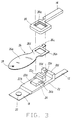
- Fig. 3 is an expanded oblique view of an essential part of the protector device of Fig. 1 in an unassembled state;
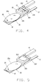
- Fig. 4 is an oblique view of the essential part of Fig. 3 in an intermediate assembled state; and
- Fig. 5 is an oblique view of the essential part of Fig, 3 in an assembled state.
- A protective device in an embodiment of the present invention has a flat box shaped housing or
casing 10 having an open and a closed end made from an electrically insulating material such as nylon which accommodates the essential parts of the device. A pair ofconnective terminals casing 10 with one end of each terminal protruding from the open end ofcase 10. The open end ofcasing 10 is tightly closed or sealed with an electrically insulatingresinous material 16 such as an epoxy which tightly holdsterminals - In the
casing 10, anelectroconductive plate 18 is provided which extends fromconnective terminal 12 along a bottom surface of the inner wall of thecasing 10 to the closed end ofcasing 10 and acts as a fixed electrode for the protector. A fixedcontact 20 made, for example, of a silver alloy is joined near the end of this fixed electrode adjacent the closed end of the casing. The tip of thefixed electrode 18 is inserted into and fixed in agroove 10a that has been formed on the closed end ofcasing 10 to thereby firmly holdfixed electrode 18 in a straight line positioned along the surface of the inner wall of the casing and to position thefixed contact 20 at a preselected location. - Adjacent sealing
resinous material 16 extending inward toward the closed end ofcasing 10 positioned onfixed electrode 18, an electrically insulating resin block is provided. Preferably,resin block 22 is joined with thefixed electrode 18. An opening 22a is preferably formed at the middle part of thisresin block 22 and, in this opening 22a, aPTC thermistor element 24 is installed. Typically,PTC element 24 is a flat parallelepiped body in which its lower half is contained within opening 22a. A lowerelectrode terminal face 24a ofPTC element 24 is in electrical contact withfixed electrode 18 by conventional means such as an electroconductive silver epoxy. It is to be understood however, if a device of the present invention is not to have a "self hold" feature, opening 22a andPTC element 24 can be replaced with an insulating block member in the shape ofPTC element 24. This block is preferably formed integrally as part ofresin block 22. - As shown in Fig. 3, resin block has a
base portion 22b which extends fromterminal 12 to near the position of fixedcontact 20 totally surroundingopening 22a. Thisbase portion 22b coversfixed electrode 18 except when the opening 22a is provided withinbase portion 22b. A front part ofbase portion 22b toward the closed end ofcasing 10 has a thickness which is smaller than the thickness of thePTC element 24. Because of this fact,PTC element 24 is made adiabatic from thefixed electrode 18 and its surroundings, so that the heating of thepositive property element 24 is effectively directed tomovable electrode 26 as will be described later. -
Resin block 22 has a square pillar orpost portion 22c arising from a slightly raised portion ofbase portion 22b positioned adjacent opening 22a away from the closed end ofcasing 10.Pillar portion 22c has a height fromfixed electrode 18 which is higher than a topelectrode terminal face 24b ofPTC element 24. Additionally, there is anend portion 22d ofblock 22 which extends upwardly to a height higher than the topelectrode terminal face 24b of PTC element 24 (generally of the same height aspillar portion 22c) positioned adjacent to sealingresin 16 generally whereterminal 12 andfixed electrode 18 are joined. Inend portion 22d there is agroove 22e formed for receiving the externalconnective terminal 14 and amovable electrode 26. -
Movable electrode 26 is made of an electrically conductive material and has abimetal part 26a typically in a generally oval shape. Anengagement part 26b in the shape of an open square ring or a frame is integrally connected by abase portion 26d tobimetal 26a and a hook-shaped engagement part 26c extends outward from one end of frame-shaped engagement part 26b opposite tobase portion 26d. At the tip of thebimetal 26a farthest away fromengagement part 26c, amovable contact 28 typically made of a silver alloy is mounted onbimetal part 26a.
Movable electrode 26 is positioned in such a manner onblock 22 thatpillar portion 22c ofblock 22 is received in the opening of the frame-shaped engagement part 26b and that the hook-shaped engagement part 26c is received ingroove 22e ofwall 22d. Further,electrode 26 is installed so that thebase portion 26d of thebimetal part 26a is placed on top of theelectrode terminal face 24b ofPTC element 24 withmovable contact 28 in engagement with fixedcontact 20. - Moreover, the surface between both of the raised
surfaces electrode terminal face 24b ofPTC element 24 to thereby provide that themovable electrode 26 does not compressively adhere to the surface ofresin block 22. - External
connective terminal 14 has aholding part 30 which is in the shape of a hollow square ring or a frame which extends from and is integrally formed therewith. At the peripheral part of the central opening of this frame-shaped holdingpart 30, a groove orcavity 30a is provided around such opening. As shown in Fig. 4, this frame-shaped holding part 30 is super-imposed on frame-shaped engagement part 26b ofmovable electrode 26 with a neck portion betweenpart 30 andterminal 14 being received ingroove 22e ofwall 22d along with hook-shaped engagement part 26c. - As shown in Fig. 5, a portion of
pillar portion 22c of theresin block 22 is staked typically by heat or ultrasonic means to fill thecavity 30a of the frame-shapedholding part 30 thereby compressively holdingmovable electrode 26 and specificallybase 26d to the upperelectrode terminal face 24b ofPTC element 24. Accordingly, an electric connection is formed between thePTC element 24 and themovable electrode 26 and, at the same time, a fulcrum for the displacement of thebimetal part 26a ofmovable electrode 26 is formed. In the case of a device withoutPTC element 24 as mentioned above,movable electrode 26 and specificallybase 26d would be compressively held against the upper flat surface of the block member replacingPTC element 24. - When the complete assembly as shown in Fig. 5 is inserted into the
casing 10, the upper surface of the frame-shaped holdingpart 30 and/or the upper surface ofdeformed pillar portion 22c of theresin block 22 are caused to compressively adhere to the surfaces of the inner walls of thecasing 10. The parts of the protector are now precisely located with respect to one another within the casing. - The operation of the protective device of the present invention will now be explained below. The protective device is connected in series with an electric source (not shown) where, for example, it is to be used for the prevention of damage to the coils of an electric motor. Accordingly, either one of the two external
connective terminals casing 10 is positioned in the neighborhood of the motor coil. - In the normal original state, bimetal 26a of the
movable electrode 26 holdsmovable contact 28 in electrical contact engagement to fixedcontact 20. The electric current that flows from the terminal 14 in this original state to terminal 12 passes through the frame-shaped holdingpart 30, the frame-shapedengagement part 26b of themovable electrode 26, thebase 26d and thebimetal part 26a, themovable contact 28, the fixedcontact 20 and the fixedelectrode 18. - When the electric current starts flowing, bimetal 26a is heated mainly by its own resistance heating and to a much lesser extent by the resistance heating of the conductors around it, in addition to the heat it receives from the motor coils through
casing 10. Despite such heating, thebimetal part 26a remains at its original position with the contacts in the closed state unless the temperature reaches an action temperature due to an overcurrent and/or overheat condition so that the electric current flows between bothelectrodes PTC element 24 and thus the element is scarcely heated. - When the action temperature is reached due to heating by an overcurrent or by the heating of the load, the
bimetal element 26a is displaced and snaps so that its tip is elevated, as is shown in Fig. 2. Because of the displacement of thebimetal part 26a, themovable contact 28 becomes separated from the fixedcontact 20, thereby bringing about an open contact state which stops the flow of current between the contacts. - With the contacts in the open state in this manner, the voltage between both
electrodes PTC element 24 and it starts to conduct electricity with a result that heating takes place. By proper choice of characteristics forPTC element 24, it will function as a fixed temperature heater. Due to the device design, the heat from thePTC element 24 is effectively all transmitted to thebimetal part 26b. - The heating of
PTC element 24 as described above results in the bimetal 26a element being held at the displaced position and the twocontacts - In order to remove this self-maintained open state of the contacts (self hold condition), it is necessary to terminate the voltage that is impressed between both of the external
connective terminals - In the protective device of this embodiment which has been described above, the
resin block 22 which has been fixed to the fixedelectrode 18 is staked by heat or the like to thecavity 30a of the frame-shaped holdingpart 30, and themovable electrode 26 is caused to compressively adhere to the surface of theupper electrode terminal 24b of PTC element for good electric connection and to form a fulcrum point for the displacement of thebimetal part 26a of themovable electrode 26. - According to such a construction, the
PTC element 24 can maintain satisfactory electric contact withmovable electrode 26 not only in the state of the contact being closed but also in the state of the contact being opened.Base part 26d ofmovable electrode 26 is always compressively in contact withcontact surface 24b ofPTC element 24. - In view of the fact that the
bimetal part 26a of themovable electrode 26 is maintained in contact withPTC element 24 not by binding but by compressive adhesion at itsbase part 26d, it is not restricted by the thermal expansion, thereby making it possible to carry out the action (displacement) of the bimetal in a smooth fashion and guaranteeing a stable and accurate contact opening and closing action. - Moreover, there is no need to provide for an electroconductive spring between the two
electrodes casing 10. - In the above described embodiment, a bimetal 26a was formed as a part of the
movable electrode 26. However, it is possible to constitute the movable electrode and the bimetal separately, with the movable electrode being caused to be displaced by the displacement of the bimetal. In such a case, it will be possible to adopt a construction in which the movable electrode is caused to compressively adhere to the PTC element at a prescribed location. - In the above described embodiment, the
installation hole 22a of theresin block 22 was made rectangular for the purpose of installing the positive characteristic thermistor which was a flat rectangular parallelopipedon. In the case where a positive characteristic thermistor in the shape of a disc is to be used, theinstallation hole 22a can be made in a circular shape. Further, a plurality of PTC element can be installed. - In the above described embodiment, the holding
part 30 was formed integrally with the externalconnective terminal 14, thereby reducing the number of parts required. However, it will be possible to form both of them separately. - It should be understood that although a generally particular embodiment of this invention has been described by way of illustrating the invention, the invention includes all modifications and equivalents of the disclosed embodiments falling within the scope of the appended claims.
Claims (10)
- A compact protector device for a load with a self hold feature comprising a housing, a fixed and a movable electrode means contained within said housing with one of said electrode means for connection to said load and the other for connection to a source of electric power, said movable electrode means including a heat responsive bimetal member having a movable contact attached thereto and positioned to engage and disengage upon action of said bimetal member with a fixed contact attached to said fixed electrode means, a positive temperature coefficient (PTC) element positioned spaced apart of said contacts in direct heat transfer relationship with said bimetal member between said fixed and said movable electrode means and electrically connected in parallel with a current path between said fixed and movable electrode means through said fixed and movable contacts so as to carry significant current between the electrodes when said fixed and movable contacts are disengaged thereby supplying generally constant heating to said bimetal member, and an insulating holding means compressively holding said movable electrode means in electrical contact with said PTC element and forming a fulcrum point for action of said bimetal member.
- A compact protector device according to claim 1 wherein said insulating holding means has a flat bottom portion fixed to said fixed electrode means with an aperture therein for receiving said PTC element to provide for maximized heating to said movable electrode means, said PTC element having a bottom surface extending through the aperture in said flat bottom portion electrically contacting said fixed electrode.
- A compact protector device according to claim 2 wherein said insulating holding means further includes a post portion extending vertically upward from said flat bottom portion of said insulating holding means on the opposite side of said PTC element from said contacts, said post portion being received in an aperture in said movable electrode means and having a deformed top portion at the distal end for compressively holding said movable electrode means against a top contact surface of said PTC element.
- A compact protector device of claim 1 wherein said housing has a inner wall surface which compressively engages said fixed and movable electrode means and said insulating holding means.
- A compact protector device of claim 1 wherein said movable electrode means comprises said bimetal member and a terminal portion and said stationary electrode means comprises a plate portion and a terminal portion, said terminal portions extending out from said housing.
- A compact protector device of claim 5 wherein said housing has an open and a closed end in which said open end is sealed around said terminal portions extending therefrom with an electrically insulating material and said closed end has a groove for precisely positioning said fixed electrode means.
- A compact protector device for a load comprising a housing, a fixed and a movable electrode means contained within said housing with one of said electrode means for connection to said load and the other for connection to a source of electric power, said movable electrode means including a heat responsive bimetal member having a movable contact attached thereto and positioned to engage and disengage upon action of said bimetal member with a fixed contact attached to said fixed electrode means, and an insulating holding means having a flat bottom portion fixed to said fixed electrode means, a post portion extending vertically upward from said flat bottom portion of said insulating holding means and a block portion also extending vertically upward from said flat bottom portion but to a height less than the height of said post portion and positioned between said post portion and said contacts in said device, said post portion being received in an aperture in said movable electrode means and having a deformed top portion at the distal end for compressively holding said movable electrode means against a top contact surface of said block portion for accurately positioning said fixed electrode means and said movable electrode means relative to one another and to form a fulcrum point for action of said bimetal member.
- A compact protector device of claim 7 wherein said housing has a inner wall surface which compressively engages said fixed and movable electrode means and said insulating holding means.
- A compact protector device of claim 7 wherein said movable electrode means comprises said bimetal member and a terminal portion and said stationary electrode means comprises a plate portion and a terminal portion, said terminal portions extending out from said housing.
- A compact protector device of claim 9 wherein said housing has an open and a closed end in which said open end is sealed around said terminal portions extending therefrom with an electrically insulating material and said closed end has a groove for precisely positioning said fixed electrode means.
Applications Claiming Priority (2)
| Application Number | Priority Date | Filing Date | Title |
|---|---|---|---|
| JP6090559A JPH07282701A (en) | 1994-04-05 | 1994-04-05 | Self-holding protector |
| JP90559/94 | 1994-04-05 |
Publications (3)
| Publication Number | Publication Date |
|---|---|
| EP0676786A2 true EP0676786A2 (en) | 1995-10-11 |
| EP0676786A3 EP0676786A3 (en) | 1996-04-24 |
| EP0676786B1 EP0676786B1 (en) | 1999-02-17 |
Family
ID=14001780
Family Applications (1)
| Application Number | Title | Priority Date | Filing Date |
|---|---|---|---|
| EP95302169A Expired - Lifetime EP0676786B1 (en) | 1994-04-05 | 1995-03-31 | Compact protector |
Country Status (4)
| Country | Link |
|---|---|
| US (1) | US5607610A (en) |
| EP (1) | EP0676786B1 (en) |
| JP (1) | JPH07282701A (en) |
| DE (1) | DE69507848T2 (en) |
Cited By (8)
| Publication number | Priority date | Publication date | Assignee | Title |
|---|---|---|---|---|
| FR2731113A1 (en) * | 1995-02-23 | 1996-08-30 | Sanyo Electric Co | Battery pack overcharging protection system |
| DE19703758A1 (en) * | 1996-01-29 | 1997-07-31 | Uchiya Thermostat | Thermal protection device e.g. for small inner spaces of housings |
| US5689173A (en) * | 1995-02-07 | 1997-11-18 | Sanyo Electric Co., Ltd. | Battery pack |
| GB2339967A (en) * | 1998-06-13 | 2000-02-09 | Apt Electronics Limited | Electronic control system with thermistor and bi-metallic str ip switch |
| EP1107344A4 (en) * | 1999-05-17 | 2007-08-15 | Matsushita Electric Industrial Co Ltd | CIRCUIT AND DEVICE FOR SECONDARY ACCUMULATOR PROTECTION |
| US7301434B1 (en) * | 2006-05-12 | 2007-11-27 | Sensata Technologies, Inc. | Thermally responsive electrical switch |
| EP1513172A4 (en) * | 2002-06-11 | 2008-12-31 | Uchiya Thermostat | Direct current cutoff switch |
| EP1513173A4 (en) * | 2002-06-11 | 2008-12-31 | Uchiya Thermostat | Direct current cutoff switch |
Families Citing this family (36)
| Publication number | Priority date | Publication date | Assignee | Title |
|---|---|---|---|---|
| JP4128250B2 (en) * | 1997-10-16 | 2008-07-30 | 日本テクニカ株式会社 | Thermal protector for power supply |
| US6191680B1 (en) * | 1998-02-23 | 2001-02-20 | HOFSäSS MARCEL | Switch having a safety element |
| US5936510A (en) * | 1998-05-22 | 1999-08-10 | Portage Electric Products, Inc. | Sealed case hold open thermostat |
| DE19847209C2 (en) * | 1998-10-13 | 2002-04-25 | Marcel Hofsaes | Switch with an insulating carrier |
| US6020807A (en) * | 1999-02-23 | 2000-02-01 | Portage Electric Products, Inc. | Sealed case hold open thermostat |
| JP3756700B2 (en) * | 1999-07-22 | 2006-03-15 | ウチヤ・サーモスタット株式会社 | Thermal protector |
| JP3190024B2 (en) | 1999-08-18 | 2001-07-16 | 日本テキサス・インスツルメンツ株式会社 | Battery protection device and method of manufacturing the same |
| JP3600781B2 (en) * | 2000-06-06 | 2004-12-15 | 株式会社日立製作所 | Protection device for hermetic electric compressor, hermetic electric compressor and cooling system using the same |
| US6707372B2 (en) * | 2000-10-04 | 2004-03-16 | Honeywell International, Inc. | Thermal switch containing preflight test feature and fault location detection |
| JP4471479B2 (en) * | 2000-10-13 | 2010-06-02 | ウチヤ・サーモスタット株式会社 | Thermal protector |
| JP4338332B2 (en) * | 2001-03-02 | 2009-10-07 | ウチヤ・サーモスタット株式会社 | Thermal protector |
| JP4424870B2 (en) * | 2001-03-19 | 2010-03-03 | 株式会社センサータ・テクノロジーズジャパン | Protector |
| US6771159B2 (en) * | 2001-11-08 | 2004-08-03 | Airpax Corporation L.L.C. | Contact spring for miniature thermostat |
| DE10235650B4 (en) * | 2002-08-02 | 2006-04-27 | INTER CONTROL Hermann Köhler Elektrik GmbH & Co KG | Thermal overload protection |
| DE112006002712B4 (en) * | 2005-10-14 | 2011-10-27 | Uchiya Thermostat Co., Ltd. | temperature switch |
| DE102006001714A1 (en) * | 2005-10-28 | 2007-05-03 | Temic Automotive Electric Motors Gmbh | Device for heating an energy store in a motor vehicle |
| CN101529546B (en) * | 2006-10-30 | 2012-01-25 | 打矢恒温器株式会社 | Thermal protector |
| US7326887B1 (en) * | 2006-12-13 | 2008-02-05 | Sensata Technologies, Inc. | Modified reset motor protector |
| DE112008003632B4 (en) | 2008-01-28 | 2023-04-06 | Uchiya Thermostat Co., Ltd. | heat protection |
| JP5174893B2 (en) * | 2008-04-10 | 2013-04-03 | ウチヤ・サーモスタット株式会社 | External operation type thermal protector |
| CN102007561B (en) * | 2008-04-18 | 2014-07-02 | 泰科电子日本合同会社 | Circuit protection device |
| DE102008049507A1 (en) * | 2008-09-29 | 2010-04-01 | Ellenberger & Poensgen Gmbh | Miniature circuit breaker |
| CN101819905B (en) * | 2010-04-09 | 2012-09-26 | 扬州宝珠电器有限公司 | Built-in protector for electric heating tube |
| CN103081051B (en) | 2010-09-24 | 2015-12-16 | 埃伦贝格尔及珀恩斯根有限公司 | Miniature safety switch |
| CN104025235B (en) * | 2011-10-14 | 2016-08-24 | 小松电子部品有限公司 | A circuit breaker, a safety circuit equipped with the circuit breaker, and a secondary battery |
| CN104011823B (en) * | 2011-10-20 | 2017-05-24 | 泰科电子日本合同会社 | Protection device |
| WO2013094725A1 (en) * | 2011-12-22 | 2013-06-27 | 株式会社小松ライト製作所 | Breaker, and safety circuit and secondary battery pack equipped with same |
| JP5941301B2 (en) * | 2012-03-06 | 2016-06-29 | 株式会社小松ライト製作所 | Breaker, safety circuit including the same, and secondary battery |
| JP2013246977A (en) * | 2012-05-25 | 2013-12-09 | Komatsulite Mfg Co Ltd | Breaker, and safety circuit and secondary battery circuit including the same |
| EP2988313B2 (en) * | 2013-04-19 | 2023-03-29 | Littelfuse Japan G.K. | Protective device |
| JP6408822B2 (en) * | 2014-07-30 | 2018-10-17 | ボーンズ株式会社 | Breaker, safety circuit including the same, and secondary battery circuit |
| JP2016035822A (en) * | 2014-08-01 | 2016-03-17 | 株式会社小松ライト製作所 | Electric component and circuit board including the same and secondary battery circuit |
| WO2017010830A1 (en) * | 2015-07-14 | 2017-01-19 | 주식회사 비티케이 | Overload protection device for compressor motor |
| JP2017079154A (en) * | 2015-10-21 | 2017-04-27 | エヌイーシー ショット コンポーネンツ株式会社 | Thermal protector |
| JP7064350B2 (en) * | 2018-02-27 | 2022-05-10 | ボーンズ株式会社 | Breaker and safety circuit with it |
| DE102023102302B3 (en) * | 2023-01-31 | 2024-03-28 | Marcel P. HOFSAESS | Temperature dependent switch |
Family Cites Families (8)
| Publication number | Priority date | Publication date | Assignee | Title |
|---|---|---|---|---|
| FR1324518A (en) * | 1961-05-01 | 1963-04-19 | Mechanical Products Inc | Fast-acting heat-sensitive devices, especially for electrical switches |
| NL277796A (en) * | 1961-05-01 | |||
| NL7004367A (en) * | 1970-03-26 | 1971-09-28 | ||
| US4201735A (en) * | 1978-09-08 | 1980-05-06 | Fasco Industries, Inc. | Method of manufacturing a choke control device |
| DE2943922A1 (en) * | 1979-10-31 | 1981-05-14 | Ego Elektro Blanc & Fischer | TEMPERATURE DETECTOR TO DISPLAY THE TEMPERATURE OF A GLASS-CERAMIC COOKING SURFACE |
| US4413174A (en) * | 1980-02-04 | 1983-11-01 | Texas Instruments Incorporated | Glow plug duty cycle modulating apparatus |
| JP3052349B2 (en) * | 1990-07-31 | 2000-06-12 | 松下電器産業株式会社 | Thermal protector |
| JPH05282977A (en) * | 1992-03-30 | 1993-10-29 | Texas Instr Japan Ltd | Overcurrent protecting device |
-
1994
- 1994-04-05 JP JP6090559A patent/JPH07282701A/en active Pending
-
1995
- 1995-03-31 DE DE69507848T patent/DE69507848T2/en not_active Expired - Fee Related
- 1995-03-31 EP EP95302169A patent/EP0676786B1/en not_active Expired - Lifetime
- 1995-04-05 US US08/417,344 patent/US5607610A/en not_active Expired - Fee Related
Cited By (9)
| Publication number | Priority date | Publication date | Assignee | Title |
|---|---|---|---|---|
| US5689173A (en) * | 1995-02-07 | 1997-11-18 | Sanyo Electric Co., Ltd. | Battery pack |
| FR2731113A1 (en) * | 1995-02-23 | 1996-08-30 | Sanyo Electric Co | Battery pack overcharging protection system |
| DE19703758A1 (en) * | 1996-01-29 | 1997-07-31 | Uchiya Thermostat | Thermal protection device e.g. for small inner spaces of housings |
| DE19703758C2 (en) * | 1996-01-29 | 2000-12-28 | Uchiya Thermostat | Temperature switch |
| GB2339967A (en) * | 1998-06-13 | 2000-02-09 | Apt Electronics Limited | Electronic control system with thermistor and bi-metallic str ip switch |
| EP1107344A4 (en) * | 1999-05-17 | 2007-08-15 | Matsushita Electric Industrial Co Ltd | CIRCUIT AND DEVICE FOR SECONDARY ACCUMULATOR PROTECTION |
| EP1513172A4 (en) * | 2002-06-11 | 2008-12-31 | Uchiya Thermostat | Direct current cutoff switch |
| EP1513173A4 (en) * | 2002-06-11 | 2008-12-31 | Uchiya Thermostat | Direct current cutoff switch |
| US7301434B1 (en) * | 2006-05-12 | 2007-11-27 | Sensata Technologies, Inc. | Thermally responsive electrical switch |
Also Published As
| Publication number | Publication date |
|---|---|
| US5607610A (en) | 1997-03-04 |
| DE69507848T2 (en) | 1999-08-05 |
| EP0676786A3 (en) | 1996-04-24 |
| JPH07282701A (en) | 1995-10-27 |
| DE69507848D1 (en) | 1999-03-25 |
| EP0676786B1 (en) | 1999-02-17 |
Similar Documents
| Publication | Publication Date | Title |
|---|---|---|
| US5607610A (en) | Compact protector | |
| US7075403B2 (en) | Motor protector particularly useful with hermetic electromotive compressors | |
| US5337036A (en) | Miniaturized thermal protector with precalibrated automatic resetting bimetallic assembly | |
| US10600597B2 (en) | Miniature safety switch | |
| KR930004816B1 (en) | Refrigerator Compressor Motor System and Motor Protector | |
| US5998051A (en) | Current interrupter for electrochemical cells | |
| US4167721A (en) | Hermetic motor protector | |
| US6503647B1 (en) | Battery protection device and method of making same | |
| EP0177652B1 (en) | Motor protector particularly suited for use with compressor motors | |
| US4490704A (en) | Thermally responsive switching device | |
| JPH0430130B2 (en) | ||
| JP2005129471A (en) | Thermal protector | |
| US5939970A (en) | Thermally responsive switch | |
| US4224591A (en) | Motor protector with metal housing and with preformed external heater thereon | |
| TW382828B (en) | Current interrupter for electrochemical cells | |
| US20240258053A1 (en) | Temperature-dependent switch | |
| JP2799204B2 (en) | A device that combines a motor protection device and a starter | |
| KR100563779B1 (en) | Thermally-actuated switch | |
| JP3200985U (en) | Thermal protector | |
| JPS6025855B2 (en) | Thermal response switch | |
| WO2003071131A1 (en) | Thermally-actuated switch | |
| JPH0745169A (en) | Self-hold type overcurrent protective device | |
| JP2660545B2 (en) | Switch device | |
| JPH11297174A (en) | Safety device | |
| US2651748A (en) | Electrical overload protector |
Legal Events
| Date | Code | Title | Description |
|---|---|---|---|
| PUAI | Public reference made under article 153(3) epc to a published international application that has entered the european phase |
Free format text: ORIGINAL CODE: 0009012 |
|
| AK | Designated contracting states |
Kind code of ref document: A2 Designated state(s): DE FR GB IT NL |
|
| PUAL | Search report despatched |
Free format text: ORIGINAL CODE: 0009013 |
|
| AK | Designated contracting states |
Kind code of ref document: A3 Designated state(s): DE FR GB IT NL |
|
| 17P | Request for examination filed |
Effective date: 19960805 |
|
| 17Q | First examination report despatched |
Effective date: 19970711 |
|
| GRAG | Despatch of communication of intention to grant |
Free format text: ORIGINAL CODE: EPIDOS AGRA |
|
| GRAG | Despatch of communication of intention to grant |
Free format text: ORIGINAL CODE: EPIDOS AGRA |
|
| GRAG | Despatch of communication of intention to grant |
Free format text: ORIGINAL CODE: EPIDOS AGRA |
|
| GRAH | Despatch of communication of intention to grant a patent |
Free format text: ORIGINAL CODE: EPIDOS IGRA |
|
| GRAH | Despatch of communication of intention to grant a patent |
Free format text: ORIGINAL CODE: EPIDOS IGRA |
|
| GRAA | (expected) grant |
Free format text: ORIGINAL CODE: 0009210 |
|
| ITF | It: translation for a ep patent filed | ||
| AK | Designated contracting states |
Kind code of ref document: B1 Designated state(s): DE FR GB IT NL |
|
| PG25 | Lapsed in a contracting state [announced via postgrant information from national office to epo] |
Ref country code: NL Free format text: LAPSE BECAUSE OF FAILURE TO SUBMIT A TRANSLATION OF THE DESCRIPTION OR TO PAY THE FEE WITHIN THE PRESCRIBED TIME-LIMIT Effective date: 19990217 |
|
| REF | Corresponds to: |
Ref document number: 69507848 Country of ref document: DE Date of ref document: 19990325 |
|
| ET | Fr: translation filed | ||
| NLV1 | Nl: lapsed or annulled due to failure to fulfill the requirements of art. 29p and 29m of the patents act | ||
| PLBE | No opposition filed within time limit |
Free format text: ORIGINAL CODE: 0009261 |
|
| STAA | Information on the status of an ep patent application or granted ep patent |
Free format text: STATUS: NO OPPOSITION FILED WITHIN TIME LIMIT |
|
| 26N | No opposition filed | ||
| REG | Reference to a national code |
Ref country code: GB Ref legal event code: IF02 |
|
| PG25 | Lapsed in a contracting state [announced via postgrant information from national office to epo] |
Ref country code: IT Free format text: LAPSE BECAUSE OF NON-PAYMENT OF DUE FEES Effective date: 20050331 |
|
| REG | Reference to a national code |
Ref country code: GB Ref legal event code: 732E |
|
| REG | Reference to a national code |
Ref country code: FR Ref legal event code: TP |
|
| REG | Reference to a national code |
Ref country code: GB Ref legal event code: 732E |
|
| REG | Reference to a national code |
Ref country code: FR Ref legal event code: TP |
|
| PGFP | Annual fee paid to national office [announced via postgrant information from national office to epo] |
Ref country code: GB Payment date: 20090206 Year of fee payment: 15 |
|
| PGFP | Annual fee paid to national office [announced via postgrant information from national office to epo] |
Ref country code: DE Payment date: 20090331 Year of fee payment: 15 |
|
| PGFP | Annual fee paid to national office [announced via postgrant information from national office to epo] |
Ref country code: FR Payment date: 20090306 Year of fee payment: 15 |
|
| GBPC | Gb: european patent ceased through non-payment of renewal fee |
Effective date: 20100331 |
|
| REG | Reference to a national code |
Ref country code: FR Ref legal event code: ST Effective date: 20101130 |
|
| PG25 | Lapsed in a contracting state [announced via postgrant information from national office to epo] |
Ref country code: FR Free format text: LAPSE BECAUSE OF NON-PAYMENT OF DUE FEES Effective date: 20100331 |
|
| PG25 | Lapsed in a contracting state [announced via postgrant information from national office to epo] |
Ref country code: DE Free format text: LAPSE BECAUSE OF NON-PAYMENT OF DUE FEES Effective date: 20101001 |
|
| PG25 | Lapsed in a contracting state [announced via postgrant information from national office to epo] |
Ref country code: GB Free format text: LAPSE BECAUSE OF NON-PAYMENT OF DUE FEES Effective date: 20100331 |