EP0674724B1 - Elastomeric compression pad with both expansion and electrical pathways - Google Patents
Elastomeric compression pad with both expansion and electrical pathways Download PDFInfo
- Publication number
- EP0674724B1 EP0674724B1 EP94904868A EP94904868A EP0674724B1 EP 0674724 B1 EP0674724 B1 EP 0674724B1 EP 94904868 A EP94904868 A EP 94904868A EP 94904868 A EP94904868 A EP 94904868A EP 0674724 B1 EP0674724 B1 EP 0674724B1
- Authority
- EP
- European Patent Office
- Prior art keywords
- elastomeric material
- elastomeric
- compression pad
- pathways
- width
- Prior art date
- Legal status (The legal status is an assumption and is not a legal conclusion. Google has not performed a legal analysis and makes no representation as to the accuracy of the status listed.)
- Expired - Lifetime
Links
- 230000006835 compression Effects 0.000 title claims abstract description 86
- 238000007906 compression Methods 0.000 title claims abstract description 86
- 230000037361 pathway Effects 0.000 title claims abstract description 66
- 239000013536 elastomeric material Substances 0.000 claims abstract description 76
- 239000003463 adsorbent Substances 0.000 claims abstract description 13
- 239000000126 substance Substances 0.000 claims description 35
- RYGMFSIKBFXOCR-UHFFFAOYSA-N Copper Chemical compound [Cu] RYGMFSIKBFXOCR-UHFFFAOYSA-N 0.000 claims description 10
- 239000011230 binding agent Substances 0.000 claims description 9
- 239000000843 powder Substances 0.000 claims description 9
- PXHVJJICTQNCMI-UHFFFAOYSA-N Nickel Chemical compound [Ni] PXHVJJICTQNCMI-UHFFFAOYSA-N 0.000 claims description 8
- BQCADISMDOOEFD-UHFFFAOYSA-N Silver Chemical compound [Ag] BQCADISMDOOEFD-UHFFFAOYSA-N 0.000 claims description 8
- 229910052802 copper Inorganic materials 0.000 claims description 6
- 239000010949 copper Substances 0.000 claims description 6
- 239000003792 electrolyte Substances 0.000 claims description 6
- 239000000203 mixture Substances 0.000 claims description 6
- 239000002245 particle Substances 0.000 claims description 6
- 229910052709 silver Inorganic materials 0.000 claims description 6
- 239000004332 silver Substances 0.000 claims description 6
- OKTJSMMVPCPJKN-UHFFFAOYSA-N Carbon Chemical compound [C] OKTJSMMVPCPJKN-UHFFFAOYSA-N 0.000 claims description 4
- 239000000956 alloy Substances 0.000 claims description 4
- 229910045601 alloy Inorganic materials 0.000 claims description 4
- 229910052759 nickel Inorganic materials 0.000 claims description 4
- 238000001179 sorption measurement Methods 0.000 claims description 3
- 230000006872 improvement Effects 0.000 claims description 2
- 239000004020 conductor Substances 0.000 claims 1
- 238000005868 electrolysis reaction Methods 0.000 abstract description 15
- 239000000446 fuel Substances 0.000 abstract description 3
- 230000000712 assembly Effects 0.000 abstract 1
- 238000000429 assembly Methods 0.000 abstract 1
- 239000007800 oxidant agent Substances 0.000 abstract 1
- 230000001590 oxidative effect Effects 0.000 abstract 1
- 210000004027 cell Anatomy 0.000 description 40
- 239000003921 oil Substances 0.000 description 20
- 229920001971 elastomer Polymers 0.000 description 7
- 239000005060 rubber Substances 0.000 description 6
- 239000001257 hydrogen Substances 0.000 description 5
- 229910052739 hydrogen Inorganic materials 0.000 description 5
- 238000004519 manufacturing process Methods 0.000 description 5
- UFHFLCQGNIYNRP-UHFFFAOYSA-N Hydrogen Chemical compound [H][H] UFHFLCQGNIYNRP-UHFFFAOYSA-N 0.000 description 4
- 210000003850 cellular structure Anatomy 0.000 description 4
- 239000000463 material Substances 0.000 description 4
- QVGXLLKOCUKJST-UHFFFAOYSA-N atomic oxygen Chemical compound [O] QVGXLLKOCUKJST-UHFFFAOYSA-N 0.000 description 3
- 230000007423 decrease Effects 0.000 description 3
- 230000003247 decreasing effect Effects 0.000 description 3
- 230000001419 dependent effect Effects 0.000 description 3
- 239000007789 gas Substances 0.000 description 3
- 229910052751 metal Inorganic materials 0.000 description 3
- 239000002184 metal Substances 0.000 description 3
- 239000001301 oxygen Substances 0.000 description 3
- 229910052760 oxygen Inorganic materials 0.000 description 3
- MYMOFIZGZYHOMD-UHFFFAOYSA-N Dioxygen Chemical compound O=O MYMOFIZGZYHOMD-UHFFFAOYSA-N 0.000 description 2
- XUIMIQQOPSSXEZ-UHFFFAOYSA-N Silicon Chemical compound [Si] XUIMIQQOPSSXEZ-UHFFFAOYSA-N 0.000 description 2
- 229910052799 carbon Inorganic materials 0.000 description 2
- 230000015556 catabolic process Effects 0.000 description 2
- 239000003054 catalyst Substances 0.000 description 2
- 238000006731 degradation reaction Methods 0.000 description 2
- 229910001882 dioxygen Inorganic materials 0.000 description 2
- ZHPNWZCWUUJAJC-UHFFFAOYSA-N fluorosilicon Chemical compound [Si]F ZHPNWZCWUUJAJC-UHFFFAOYSA-N 0.000 description 2
- -1 hydrogen ions Chemical class 0.000 description 2
- 238000000034 method Methods 0.000 description 2
- 229920001296 polysiloxane Polymers 0.000 description 2
- 229910052710 silicon Inorganic materials 0.000 description 2
- 239000010703 silicon Substances 0.000 description 2
- 229920002379 silicone rubber Polymers 0.000 description 2
- 239000007787 solid Substances 0.000 description 2
- XLYOFNOQVPJJNP-UHFFFAOYSA-N water Substances O XLYOFNOQVPJJNP-UHFFFAOYSA-N 0.000 description 2
- JOYRKODLDBILNP-UHFFFAOYSA-N Ethyl urethane Chemical compound CCOC(N)=O JOYRKODLDBILNP-UHFFFAOYSA-N 0.000 description 1
- 229920000459 Nitrile rubber Polymers 0.000 description 1
- RTAQQCXQSZGOHL-UHFFFAOYSA-N Titanium Chemical compound [Ti] RTAQQCXQSZGOHL-UHFFFAOYSA-N 0.000 description 1
- 230000004888 barrier function Effects 0.000 description 1
- 230000015572 biosynthetic process Effects 0.000 description 1
- 230000008859 change Effects 0.000 description 1
- 238000006243 chemical reaction Methods 0.000 description 1
- 238000000354 decomposition reaction Methods 0.000 description 1
- 239000000806 elastomer Substances 0.000 description 1
- 230000008030 elimination Effects 0.000 description 1
- 238000003379 elimination reaction Methods 0.000 description 1
- 238000004880 explosion Methods 0.000 description 1
- 239000012530 fluid Substances 0.000 description 1
- 238000012423 maintenance Methods 0.000 description 1
- 150000002739 metals Chemical class 0.000 description 1
- 239000005518 polymer electrolyte Substances 0.000 description 1
- 229920002635 polyurethane Polymers 0.000 description 1
- 239000004814 polyurethane Substances 0.000 description 1
- 239000004945 silicone rubber Substances 0.000 description 1
- 239000010935 stainless steel Substances 0.000 description 1
- 229910001220 stainless steel Inorganic materials 0.000 description 1
- 239000010936 titanium Substances 0.000 description 1
- 229910052719 titanium Inorganic materials 0.000 description 1
Images


Classifications
-
- H—ELECTRICITY
- H01—ELECTRIC ELEMENTS
- H01M—PROCESSES OR MEANS, e.g. BATTERIES, FOR THE DIRECT CONVERSION OF CHEMICAL ENERGY INTO ELECTRICAL ENERGY
- H01M8/00—Fuel cells; Manufacture thereof
- H01M8/02—Details
- H01M8/0202—Collectors; Separators, e.g. bipolar separators; Interconnectors
- H01M8/0247—Collectors; Separators, e.g. bipolar separators; Interconnectors characterised by the form
-
- C—CHEMISTRY; METALLURGY
- C25—ELECTROLYTIC OR ELECTROPHORETIC PROCESSES; APPARATUS THEREFOR
- C25B—ELECTROLYTIC OR ELECTROPHORETIC PROCESSES FOR THE PRODUCTION OF COMPOUNDS OR NON-METALS; APPARATUS THEREFOR
- C25B9/00—Cells or assemblies of cells; Constructional parts of cells; Assemblies of constructional parts, e.g. electrode-diaphragm assemblies; Process-related cell features
- C25B9/60—Constructional parts of cells
- C25B9/65—Means for supplying current; Electrode connections; Electric inter-cell connections
- C25B9/66—Electric inter-cell connections including jumper switches
-
- H—ELECTRICITY
- H01—ELECTRIC ELEMENTS
- H01B—CABLES; CONDUCTORS; INSULATORS; SELECTION OF MATERIALS FOR THEIR CONDUCTIVE, INSULATING OR DIELECTRIC PROPERTIES
- H01B1/00—Conductors or conductive bodies characterised by the conductive materials; Selection of materials as conductors
- H01B1/20—Conductive material dispersed in non-conductive organic material
- H01B1/22—Conductive material dispersed in non-conductive organic material the conductive material comprising metals or alloys
-
- H—ELECTRICITY
- H01—ELECTRIC ELEMENTS
- H01B—CABLES; CONDUCTORS; INSULATORS; SELECTION OF MATERIALS FOR THEIR CONDUCTIVE, INSULATING OR DIELECTRIC PROPERTIES
- H01B1/00—Conductors or conductive bodies characterised by the conductive materials; Selection of materials as conductors
- H01B1/20—Conductive material dispersed in non-conductive organic material
- H01B1/24—Conductive material dispersed in non-conductive organic material the conductive material comprising carbon-silicon compounds, carbon or silicon
-
- H—ELECTRICITY
- H01—ELECTRIC ELEMENTS
- H01M—PROCESSES OR MEANS, e.g. BATTERIES, FOR THE DIRECT CONVERSION OF CHEMICAL ENERGY INTO ELECTRICAL ENERGY
- H01M50/00—Constructional details or processes of manufacture of the non-active parts of electrochemical cells other than fuel cells, e.g. hybrid cells
- H01M50/50—Current conducting connections for cells or batteries
-
- H—ELECTRICITY
- H01—ELECTRIC ELEMENTS
- H01M—PROCESSES OR MEANS, e.g. BATTERIES, FOR THE DIRECT CONVERSION OF CHEMICAL ENERGY INTO ELECTRICAL ENERGY
- H01M8/00—Fuel cells; Manufacture thereof
- H01M8/02—Details
- H01M8/0202—Collectors; Separators, e.g. bipolar separators; Interconnectors
- H01M8/023—Porous and characterised by the material
- H01M8/0232—Metals or alloys
-
- H—ELECTRICITY
- H01—ELECTRIC ELEMENTS
- H01M—PROCESSES OR MEANS, e.g. BATTERIES, FOR THE DIRECT CONVERSION OF CHEMICAL ENERGY INTO ELECTRICAL ENERGY
- H01M8/00—Fuel cells; Manufacture thereof
- H01M8/02—Details
- H01M8/0202—Collectors; Separators, e.g. bipolar separators; Interconnectors
- H01M8/023—Porous and characterised by the material
- H01M8/0241—Composites
- H01M8/0243—Composites in the form of mixtures
-
- H—ELECTRICITY
- H01—ELECTRIC ELEMENTS
- H01R—ELECTRICALLY-CONDUCTIVE CONNECTIONS; STRUCTURAL ASSOCIATIONS OF A PLURALITY OF MUTUALLY-INSULATED ELECTRICAL CONNECTING ELEMENTS; COUPLING DEVICES; CURRENT COLLECTORS
- H01R13/00—Details of coupling devices of the kinds covered by groups H01R12/70 or H01R24/00 - H01R33/00
- H01R13/02—Contact members
- H01R13/22—Contacts for co-operating by abutting
- H01R13/24—Contacts for co-operating by abutting resilient; resiliently-mounted
- H01R13/2407—Contacts for co-operating by abutting resilient; resiliently-mounted characterized by the resilient means
- H01R13/2414—Contacts for co-operating by abutting resilient; resiliently-mounted characterized by the resilient means conductive elastomers
-
- Y—GENERAL TAGGING OF NEW TECHNOLOGICAL DEVELOPMENTS; GENERAL TAGGING OF CROSS-SECTIONAL TECHNOLOGIES SPANNING OVER SEVERAL SECTIONS OF THE IPC; TECHNICAL SUBJECTS COVERED BY FORMER USPC CROSS-REFERENCE ART COLLECTIONS [XRACs] AND DIGESTS
- Y02—TECHNOLOGIES OR APPLICATIONS FOR MITIGATION OR ADAPTATION AGAINST CLIMATE CHANGE
- Y02E—REDUCTION OF GREENHOUSE GAS [GHG] EMISSIONS, RELATED TO ENERGY GENERATION, TRANSMISSION OR DISTRIBUTION
- Y02E60/00—Enabling technologies; Technologies with a potential or indirect contribution to GHG emissions mitigation
- Y02E60/10—Energy storage using batteries
-
- Y—GENERAL TAGGING OF NEW TECHNOLOGICAL DEVELOPMENTS; GENERAL TAGGING OF CROSS-SECTIONAL TECHNOLOGIES SPANNING OVER SEVERAL SECTIONS OF THE IPC; TECHNICAL SUBJECTS COVERED BY FORMER USPC CROSS-REFERENCE ART COLLECTIONS [XRACs] AND DIGESTS
- Y02—TECHNOLOGIES OR APPLICATIONS FOR MITIGATION OR ADAPTATION AGAINST CLIMATE CHANGE
- Y02E—REDUCTION OF GREENHOUSE GAS [GHG] EMISSIONS, RELATED TO ENERGY GENERATION, TRANSMISSION OR DISTRIBUTION
- Y02E60/00—Enabling technologies; Technologies with a potential or indirect contribution to GHG emissions mitigation
- Y02E60/30—Hydrogen technology
- Y02E60/50—Fuel cells
-
- Y—GENERAL TAGGING OF NEW TECHNOLOGICAL DEVELOPMENTS; GENERAL TAGGING OF CROSS-SECTIONAL TECHNOLOGIES SPANNING OVER SEVERAL SECTIONS OF THE IPC; TECHNICAL SUBJECTS COVERED BY FORMER USPC CROSS-REFERENCE ART COLLECTIONS [XRACs] AND DIGESTS
- Y10—TECHNICAL SUBJECTS COVERED BY FORMER USPC
- Y10T—TECHNICAL SUBJECTS COVERED BY FORMER US CLASSIFICATION
- Y10T428/00—Stock material or miscellaneous articles
- Y10T428/24—Structurally defined web or sheet [e.g., overall dimension, etc.]
- Y10T428/24273—Structurally defined web or sheet [e.g., overall dimension, etc.] including aperture
-
- Y—GENERAL TAGGING OF NEW TECHNOLOGICAL DEVELOPMENTS; GENERAL TAGGING OF CROSS-SECTIONAL TECHNOLOGIES SPANNING OVER SEVERAL SECTIONS OF THE IPC; TECHNICAL SUBJECTS COVERED BY FORMER USPC CROSS-REFERENCE ART COLLECTIONS [XRACs] AND DIGESTS
- Y10—TECHNICAL SUBJECTS COVERED BY FORMER USPC
- Y10T—TECHNICAL SUBJECTS COVERED BY FORMER US CLASSIFICATION
- Y10T428/00—Stock material or miscellaneous articles
- Y10T428/24—Structurally defined web or sheet [e.g., overall dimension, etc.]
- Y10T428/24802—Discontinuous or differential coating, impregnation or bond [e.g., artwork, printing, retouched photograph, etc.]
- Y10T428/24893—Discontinuous or differential coating, impregnation or bond [e.g., artwork, printing, retouched photograph, etc.] including particulate material
-
- Y—GENERAL TAGGING OF NEW TECHNOLOGICAL DEVELOPMENTS; GENERAL TAGGING OF CROSS-SECTIONAL TECHNOLOGIES SPANNING OVER SEVERAL SECTIONS OF THE IPC; TECHNICAL SUBJECTS COVERED BY FORMER USPC CROSS-REFERENCE ART COLLECTIONS [XRACs] AND DIGESTS
- Y10—TECHNICAL SUBJECTS COVERED BY FORMER USPC
- Y10T—TECHNICAL SUBJECTS COVERED BY FORMER US CLASSIFICATION
- Y10T428/00—Stock material or miscellaneous articles
- Y10T428/24—Structurally defined web or sheet [e.g., overall dimension, etc.]
- Y10T428/24802—Discontinuous or differential coating, impregnation or bond [e.g., artwork, printing, retouched photograph, etc.]
- Y10T428/24917—Discontinuous or differential coating, impregnation or bond [e.g., artwork, printing, retouched photograph, etc.] including metal layer
-
- Y—GENERAL TAGGING OF NEW TECHNOLOGICAL DEVELOPMENTS; GENERAL TAGGING OF CROSS-SECTIONAL TECHNOLOGIES SPANNING OVER SEVERAL SECTIONS OF THE IPC; TECHNICAL SUBJECTS COVERED BY FORMER USPC CROSS-REFERENCE ART COLLECTIONS [XRACs] AND DIGESTS
- Y10—TECHNICAL SUBJECTS COVERED BY FORMER USPC
- Y10T—TECHNICAL SUBJECTS COVERED BY FORMER US CLASSIFICATION
- Y10T428/00—Stock material or miscellaneous articles
- Y10T428/249921—Web or sheet containing structurally defined element or component
- Y10T428/249953—Composite having voids in a component [e.g., porous, cellular, etc.]
- Y10T428/249967—Inorganic matrix in void-containing component
- Y10T428/24997—Of metal-containing material
-
- Y—GENERAL TAGGING OF NEW TECHNOLOGICAL DEVELOPMENTS; GENERAL TAGGING OF CROSS-SECTIONAL TECHNOLOGIES SPANNING OVER SEVERAL SECTIONS OF THE IPC; TECHNICAL SUBJECTS COVERED BY FORMER USPC CROSS-REFERENCE ART COLLECTIONS [XRACs] AND DIGESTS
- Y10—TECHNICAL SUBJECTS COVERED BY FORMER USPC
- Y10T—TECHNICAL SUBJECTS COVERED BY FORMER US CLASSIFICATION
- Y10T428/00—Stock material or miscellaneous articles
- Y10T428/25—Web or sheet containing structurally defined element or component and including a second component containing structurally defined particles
-
- Y—GENERAL TAGGING OF NEW TECHNOLOGICAL DEVELOPMENTS; GENERAL TAGGING OF CROSS-SECTIONAL TECHNOLOGIES SPANNING OVER SEVERAL SECTIONS OF THE IPC; TECHNICAL SUBJECTS COVERED BY FORMER USPC CROSS-REFERENCE ART COLLECTIONS [XRACs] AND DIGESTS
- Y10—TECHNICAL SUBJECTS COVERED BY FORMER USPC
- Y10T—TECHNICAL SUBJECTS COVERED BY FORMER US CLASSIFICATION
- Y10T428/00—Stock material or miscellaneous articles
- Y10T428/25—Web or sheet containing structurally defined element or component and including a second component containing structurally defined particles
- Y10T428/256—Heavy metal or aluminum or compound thereof
-
- Y—GENERAL TAGGING OF NEW TECHNOLOGICAL DEVELOPMENTS; GENERAL TAGGING OF CROSS-SECTIONAL TECHNOLOGIES SPANNING OVER SEVERAL SECTIONS OF THE IPC; TECHNICAL SUBJECTS COVERED BY FORMER USPC CROSS-REFERENCE ART COLLECTIONS [XRACs] AND DIGESTS
- Y10—TECHNICAL SUBJECTS COVERED BY FORMER USPC
- Y10T—TECHNICAL SUBJECTS COVERED BY FORMER US CLASSIFICATION
- Y10T428/00—Stock material or miscellaneous articles
- Y10T428/31504—Composite [nonstructural laminate]
- Y10T428/31678—Of metal
Definitions
- the present invention relates to a compression pad for compensating for component dimensional variations within a system and especially relates to an elastomeric compression pad for compensating for component dimensional variations within a cell and an improved cell comprising that elastomeric pad.
- An electrolysis cell is a mechanical assembly for electrolyzing water to hydrogen and oxygen gas.
- a plurality of electrolysis cells are often assembled in a single module or stack.
- Figure 1 illustrates a bi-polar electrolysis cell stack where a plurality of electrolysis cells, cell 1, cell 2, and cell 3, are stacked and electrically connected in series.
- the major cell stack components are, sequentially: anode electrode 5 , solid polymer electrolyte 7 , cathode electrode 3 , and cathode and anode chambers located in the frames 10 which surround the components. All of these components are thin, flat and rigid, with the anode electrodes 5 and cathode electrodes 3 having an active area of catalyst, 4 and 2 respectively, in contact with the electrolyte.
- Standard electrolysis cells often show compounded component dimensional variationsof 0.18 to about 0,25 mm (about 0.007 to about 0.010 inches) due to fabrication limitations, with additional dimensional variations of up to about 0.002 mm/mm (0.002 inches/inch) due to differential thermal expansion during electrolysis cell operation.
- An elastic component known as a compression pad 9
- a compression pad 9 is included in electrolysis cell stacks in order to attain the electrolysis cell stack requirements of uniform contact pressure over the active area of the anode and cathode electrodes, sufficient contact pressure to prevent movement of the electrolyte which causes degradation thereof, and fluid tight seals to prevent mixing of the product gases which can cause an explosion.
- this compression pad 9 compensates for dimensional variations to maintain uniform contact over the active areas up to pressures of about 3.54MPa (500psig) for an electrically conductive compression pad, and up to pressures of about 6.30 MPa (900 psig) for an electrically non-conductive compression pad.
- the compression pad can compensate for dimensional variations at pressures up to about 6.30 MPa (900 psig), more and more applications require increased gas delivery pressure capabilities, many beyond the capability of prior art compression pads.
- Increased pressure requirements were initially addressed by enclosing the entire cell stack within a pressure vessel to limit the maximum load across the compression pad to about 1.48MPa(200psig).
- the compression pad was vented to the vessel and the stack was operated in a balanced pressure mode, i.e. both gases were produced at approximately the same pressure of up to about 41.47 MPa (6,000psig).
- the vessel plus the pressure controls associated with this configuration however, added significant weight and expense to the system.
- Electrolysis cell stacks without a pressure vessel are simpler, lighter, and less expensive than those requiring pressure vessels.
- the compression pad is totally sealed, i.e. not externally vented, and must withstand significantly higher pressure differentials, approximately equal to the sum of the highest internal pressure during operation(up to about 6.99MPa (1,000 psig)) and the compression required to maintain uniform electrical contact.
- This differential pressure can attain about 10.44MPa (1,500psig) while the compression pad 9 can only effectively compensate for dimensional variations up to about 6.30MPa (900psig). Therefore, at high pressures, exceeding about 6.30MPa (900psig), the traditional material and design are only marginally useful as a compression pad.
- the EP-A-0 425 316 discloses an elastomeric compression pad comprising expansion pathways located across the width of the pad and electrical pathways containing a conductive substance across the width of the path.
- the present invention relates to an elastomeric compression pad as described in claim 1 for compensating for component dimensional variations.
- This compression pad comprises an elastomeric material having an overall uncompressed length and a width, with a plurality of expansion pathways located across the width of said elastomeric material. These expansion pathways have sufficient volume to allow the elastomeric material to substantially maintain its overall uncompressed length while in a compressed state.
- the elastomeric material further has a plurality of electrical pathways containing a sufficient amount of conductive substance to form an electrically conductive path across the width of the elastomeric material.
- the present invention also relates to an improved electrolysis cell as described in claim 8 for operating at pressures up to about 20.78MPa (3,000 psig).
- the electrolysis cell comprises an anode electrode, a cathode electrode, and an electrolyte disposed therebetween while the improvement is the elastomeric compression pad.
- Figure 1 an illustration of a bi-polar electrolysis cell stack.
- Figure 2 is an embodiment of the prior art compression pad.
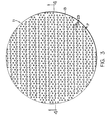
- Figure 3 is an embodiment of the elastomeric compression pad of the present invention.
- Figure 4 is a cross-sectional view of the uncompressed elastomeric compression pad of Figure 3.
- Figure 5 is a cross-sectional view of the compressed elastomeric compression pad of Figure 3.
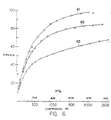
- Figure 6 is a graph of both the strain of the prior art elastomeric compression pad and the elastomeric compression pad of the present invention at given pressures.
- the compression pad of the present invention compensates for dimensional variations in the components of a fuel cell, electrolysis cell, or cell stack thereof (hereinafter referred to as cell) to maintain uniform contact pressure over the active areas of the electrodes in the cell over the entire range of operating conditions up to about 20.78MPa (3,000 psig) without the use of a pressure vessel.
- the compression pad is comprised of an elastomeric material having an electrically conductive substance for establishing an electrical path through the elastomeric material and a means for compensating for lateral expansion and for supporting the conductive substance.
- the elastomeric material is selected based upon the operating conditions of the cell. These operating conditions may include pressure and temperature, as well as the thickness and deformation of the compression pad during use. Since the compression pad and therefore the elastomeric material compensates for component dimensional variations, the elastomeric material must be compressible such that the size of the compressed elastomeric material substantially coincides with the component dimensional variation within the cell.
- the compressibility range of the compression pad is dependent upon its hardness. If the elastomeric material has a shore A durometer hardness of about 100, it is basically solid and incompressible and therefore not capable of compensating for the component dimensional variations. In contrast, if the elastomeric material has a shore A durometer hardness less than about 50, it is soft and incapable of maintaining uniform contact pressure and preventing movement of the electrolyte.
- elastomeric material including rubbers such as silicon, fluorosilicon rubber, nitrile rubbers, and polyurethane, and other materials having a shore A durometer hardness of about 70 to about 95 are suitable elastomeric materials, with those having a durometer hardness of about 80 to about 90 preferred for pressures up to about 20.78MPa (3,000psig), and especially preferred for pressures of about 3.54MPa(500psig) to about 13.89MPa (2,000 psig).
- One such rubber is silicone rubber which has a durometer hardness of about 80, produced by General Electric Company, Waterford, New York. Other rubber materials such as urethane and fluorosilicones can be utilized. It would be noted that the hardness of the elastomeric material can be decreased with the use of expansion pathways (discussed below), and therefore the use of elastomeric material having a shore A durometer hardness above about 100 is feasible.
- the elastomeric material in addition to possessing the desirable hardness, should also be capable of maintaining its uncompressed length while in the compressed state.
- the pad when pressure is applied across the cell, to the compression pad, via the production of hydrogen and oxygen at different pressures, the pad is compressed.
- This compression causes the elastomeric material width to decrease and its length, therefore, to increase or expand.
- this direction of expansion is referred to as lateral. Since, in the present application, the compression pad is used within a cell stack, which has rigid external walls, the overall length of the elastomeric material cannot increase. Consequently, compensation for this expansion must be incorporated into the elastomeric material itself.
- Compensation can comprise the use of pathways through the elastomeric material having sufficient volume to consume the laterally expanded elastomeric material, thereby allowing the compression pad to maintain its uncompressed length while in the compressed state.
- the pathways can be of varying geometries, and should be substantially evenly distributed throughout the elastomeric material, sufficiently large and abundant such that the elastomeric material can be compressed to a size substantially commensurate with the component dimensional variation, and preferably be located parallel to the width of the compression pad. If these pathways are not substantially uniformly distributed throughout the elastomeric material, the elastomeric material may not be capable of substantially uniform compression. Consequently, uniform contact pressure over the active areas of the electrodes may not be maintained.
- the number of pathways is dependent on the hardness of the elastomeric material, the number of pathways should be commensurate with the number of pathways necessary to compensate for the lateral expansion and to attain the desired compression, without significantly effecting the compression pad's ability to maintain uniform contact pressure over the active areas of the electrodes and sufficient contact pressure to prevent movement of the electrolyte.
- expansion phenomenon is illustrated in Figures 4 and 5 where the elastomeric material 13 is deformed and forced laterally, the direction perpendicular to the width of the compression pad, into expansion pathways 17 upon compression. Consequently, both the size of expansion pathways 17 (see Figure 4, expansion pathways 17 and Figure 5, expansion pathways 17' ) and the thickness of the elastomeric material 13 decreases.
- the expansion pathways 17 allow the deformation of the elastomeric material 13 when the compression pad 11 is compressed.
- the elastomeric material must also be electrically conductive.
- a conductive substance having an electrical resistance below about 0.01 ohms ⁇ cm and preferably about 0.006 ohms ⁇ cm or lower can be employed to impart electrical conductivity to the elastomeric material. If the conductive substance's electrical resistivity is greater than about 0.1 ohm ⁇ cm the efficiency of the cell will be reduced such that the bi-polar arrangement is impractical.
- the conductive substance is a mixture of a conductive powder such as carbon or metal powder and an elastomeric binder.
- the conductive powder possesses particle-to-particle contact through the elastomeric binder such that during operation, electrical conductivity through the conductive substance is ensured.
- Sufficient elastomeric binder is utilized to provide structural integrity and elasticity to the conductive powder while allowing particle-to-particle contact of the powder through the elastomeric binder.
- Possible powders include silver, copper, silver plated copper, and other conventional powders such as various carbons and other metals having similar low electrical resistance
- possible elastomeric binders include rubber such as silicon and fluorosilicon rubber, and other elastomers having sufficient strength and temperature stability to be compatible with the cell environment.
- a conductive substance which has proven particularly useful with the present invention is silver filled silicon rubber having an electrical resistance of about 0.004 ohm ⁇ cm to about 0.005 ohm ⁇ cm, produced by Chomerics, Inc., Woburn, Massachusetts.
- the conductive substance In order to establish the conductive path through the elastomeric material, the conductive substance should be substantially evenly distributed throughout the elastomeric material in a second plurality of pathways (hereinafter referred to as electrical pathways). As with the expansion pathways, the electrical pathways are located parallel to the width of the compression pad, and the number, size, and geometry of these pathways are adjusted empirically to achieve the optimum combination of mechanical and electrical properties which correspond to sufficient elasticity to compensate for component dimensional variations and minimal electrical resistance.
- electrical pathways are located parallel to the width of the compression pad, and the number, size, and geometry of these pathways are adjusted empirically to achieve the optimum combination of mechanical and electrical properties which correspond to sufficient elasticity to compensate for component dimensional variations and minimal electrical resistance.
- the amount and size of the electrical pathways are dependent upon the desired rigidity of the elastomeric material versus the desired conductivity. As the amount of electrical pathways increase, the elastomeric material stiffness similarly increases, thereby decreasing the compression capabilities of the compression pad. If a greater number of electrical pathways is desired, additional expansion pathways can be employed to sufficiently decrease the elastic strain of the elastomeric material, thereby compensating for the increased stiffness imparted by the conductive substance.
- the conductive substance in the electrical pathways should possess sufficient thickness to provide a conductive path from one cell, through the conductive substance, to the next cell of a stack, when the compression pad is in the compressed state while also being sufficiently less thick than the elastomeric material such that the conductive substance does not inhibit the necessary compression of the elastomeric material to compensate for the component dimensional variation.
- the preferred thickness of the conductive substance can readily be determined from the thickness of the elastomeric material and the elastic strain thereof at the desired operating pressure.
- the conductive substance should be substantially the same thickness as the elastomeric material in the compressed state.
- the conductive substance 15 is located in electrical pathways 23 in the elastomeric material 13 with expansion pathways 17 . Once elastomeric material 13 is compressed, the conductive substance 15 has substantially the same thickness as the compressed, expanded elastomeric material 13' .
- the elastomeric material Upon compression, in addition to expanding laterally, the elastomeric material often releases processing oil.
- This oil which is typically released at pressures exceeding about 6.99MPa (1,000psig), interferes with the inter-cell conductive path through the compression pad by forming an oil film on the elastomeric material across the conductive substance.
- the oil film increases the electrical resistance between the conductive substance and the cell components directly in contact therewith. Consequently, a non-conductive barrier forms between the elastomeric material and the cell components. Therefore, since use of the compression pad in a bi-polar cell stack requires maintenance of the conductive path across the elastomeric material, the conductive path must be re-established.
- One method of re-establishing the conductive path comprises removing the oil by locating an electrically conductive oil adsorbent sheet between the cell components and the elastomeric material. This oil adsorption sheet adsorbs the oil released by the elastomeric material, thereby decreasing the resistance between the conductive substance and the cell components.
- the oil adsorbent sheet is preferably capable of wicking the oil from the surface of the elastomeric material. Consequently, electrically conductive oil adsorbent sheets having porosities sufficient to wick the oil released by the elastomeric material can be employed. Porosities of about 40% and about 60% have proven useful for reducing resistivity while porosities of about 45% to about 55% in combination with a sintered oil adsorbent sheet surface is preferred and porosities of about 50% are especially preferred to substantially eliminate the electrical resistivity caused by the oil.
- Possible oil adsorbent sheets include sheets of copper, nickel, stainless steel, carbon, and alloys and mixtures thereof, and others, with an about 0.25 to 0.50mm (0.01 inch to about 0.02 inch) thick sheet of copper, nickel, or alloy thereof preferred.
- Figure 3 illustrates the compression pad of the present invention.
- This compression pad 11 has electrical and expansion pathways 23 and 17 , respectively.
- Figures 4 and 5 show cross-sectional views of the compression pad 11 of Figure 3, in an uncompressed and a compressed state, respectively.
- the uncompressed compression pad 11 clearly shows the elastomeric material 13 having expansion pathways 17 located parallel to the width of the elastomeric material.
- the elastomeric material width is the distance from the oil adsorbent sheet 19 to the oil adsorbent sheet 21 , while the length is the dimension parallel to the oil adsorbent sheets 19 and 21 .
- This compression pad 11 similarly has electrical pathways 23 with conductive substance 15 . Once the compression pad 11 has been compressed, the conductive substance 15 contacts the oil adsorbent sheets 19 and 21 thereby occupying substantially all of the electrical pathways' volume, while the compressed elastomeric material 13' occupies part or all of the expansion pathways' volume 17' .
- compression pads utilized in cell stacks preferably possess elastic strains of about 30% to about 70%. Below about 30% the strain is almost equal to normal component tolerances while above about 70%, the compression pad has been compressed to a point where it becomes substantially inflexible. Therefore, elastic strain percentages of about 35% to about 65% are preferred, with about 40% to about 60% especially preferred for the present compression pad.
- a prior art compression pad having the metal strips attains an elastic strain above 60% at a pressure of about 2.86 MPa (400 psig)and an elastic strain exceeding about 70% below 600 psig pressure (line 61).
- a prior art non-conductive compression pad maintains an elastic strain below about 60% in pressures up to about 4.14MPa (600 psig) and below about 70% in pressures up to about 6.30MPa (900 psig).
- this compression pad is non-conductive and therefore not useful for the bi-polar cell stack nor for pressure differentials greater than about 6.30 MPa (900 psig).
- the conductive compression pad of the present invention which is useful up to pressures of about 20.78 MPa (3,000 psig) maintains an elastic strain below about 60% up to pressures of about 12.5 MPa (1,800 psig) and an elastic strain below 65% up to pressures of about 17.34 MPa (2,500 psig).
Landscapes
- Chemical & Material Sciences (AREA)
- Chemical Kinetics & Catalysis (AREA)
- Electrochemistry (AREA)
- Engineering & Computer Science (AREA)
- General Chemical & Material Sciences (AREA)
- Life Sciences & Earth Sciences (AREA)
- Sustainable Energy (AREA)
- Sustainable Development (AREA)
- Manufacturing & Machinery (AREA)
- Physics & Mathematics (AREA)
- Spectroscopy & Molecular Physics (AREA)
- Dispersion Chemistry (AREA)
- Composite Materials (AREA)
- Organic Chemistry (AREA)
- Metallurgy (AREA)
- Materials Engineering (AREA)
- Electrolytic Production Of Non-Metals, Compounds, Apparatuses Therefor (AREA)
- Fuel Cell (AREA)
- Conductive Materials (AREA)
Abstract
Description
- The present invention relates to a compression pad for compensating for component dimensional variations within a system and especially relates to an elastomeric compression pad for compensating for component dimensional variations within a cell and an improved cell comprising that elastomeric pad.
- An electrolysis cell is a mechanical assembly for electrolyzing water to hydrogen and oxygen gas. To meet hydrogen and oxygen production requirements, a plurality of electrolysis cells are often assembled in a single module or stack. Figure 1 illustrates a bi-polar electrolysis cell stack where a plurality of electrolysis cells, cell 1,
cell 2, andcell 3, are stacked and electrically connected in series. The major cell stack components are, sequentially:anode electrode 5,solid polymer electrolyte 7,cathode electrode 3, and cathode and anode chambers located in theframes 10 which surround the components. All of these components are thin, flat and rigid, with theanode electrodes 5 andcathode electrodes 3 having an active area of catalyst, 4 and 2 respectively, in contact with the electrolyte. In order to ensure optimum decomposition of the water to hydrogen ions and oxygen, formation of molecular oxygen, and conversion of the hydrogen ions to molecular hydrogen, uniform current distribution across the active areas of catalyst is required. Uniform current distribution requires uniform contact pressure over these active areas. - However, uniform contact pressure over the active areas of the anode and cathode electrodes is seldom attained solely through design since each component's dimensions vary within some specified limits due to individual component fabrication by various production methods. Standard electrolysis cells often show compounded component dimensional variationsof 0.18 to about 0,25 mm (about 0.007 to about 0.010 inches) due to fabrication limitations, with additional dimensional variations of up to about 0.002 mm/mm (0.002 inches/inch) due to differential thermal expansion during electrolysis cell operation.
- An elastic component, known as a
compression pad 9, is included in electrolysis cell stacks in order to attain the electrolysis cell stack requirements of uniform contact pressure over the active area of the anode and cathode electrodes, sufficient contact pressure to prevent movement of the electrolyte which causes degradation thereof, and fluid tight seals to prevent mixing of the product gases which can cause an explosion. To date, thiscompression pad 9 compensates for dimensional variations to maintain uniform contact over the active areas up to pressures of about 3.54MPa (500psig) for an electrically conductive compression pad, and up to pressures of about 6.30 MPa (900 psig) for an electrically non-conductive compression pad. - Although the compression pad can compensate for dimensional variations at pressures up to about 6.30 MPa (900 psig), more and more applications require increased gas delivery pressure capabilities, many beyond the capability of prior art compression pads. Increased pressure requirements were initially addressed by enclosing the entire cell stack within a pressure vessel to limit the maximum load across the compression pad to about 1.48MPa(200psig). In this configuration, the compression pad was vented to the vessel and the stack was operated in a balanced pressure mode, i.e. both gases were produced at approximately the same pressure of up to about 41.47 MPa (6,000psig). The vessel plus the pressure controls associated with this configuration, however, added significant weight and expense to the system.
- Electrolysis cell stacks without a pressure vessel are simpler, lighter, and less expensive than those requiring pressure vessels. In this configuration, the compression pad is totally sealed, i.e. not externally vented, and must withstand significantly higher pressure differentials, approximately equal to the sum of the highest internal pressure during operation(up to about 6.99MPa (1,000 psig)) and the compression required to maintain uniform electrical contact. This differential pressure can attain about 10.44MPa (1,500psig) while the
compression pad 9 can only effectively compensate for dimensional variations up to about 6.30MPa (900psig). Therefore, at high pressures, exceeding about 6.30MPa (900psig), the traditional material and design are only marginally useful as a compression pad. - The EP-A-0 425 316 discloses an elastomeric compression pad comprising expansion pathways located across the width of the pad and electrical pathways containing a conductive substance across the width of the path.
- What is needed in the art is a high pressure compatible, electrically conductive compression pad useful in maintaining uniform contact at pressure differentials up to about 20.78MPa (3,000 psig).
- The present invention relates to an elastomeric compression pad as described in claim 1 for compensating for component dimensional variations. This compression pad comprises an elastomeric material having an overall uncompressed length and a width, with a plurality of expansion pathways located across the width of said elastomeric material. These expansion pathways have sufficient volume to allow the elastomeric material to substantially maintain its overall uncompressed length while in a compressed state. The elastomeric material further has a plurality of electrical pathways containing a sufficient amount of conductive substance to form an electrically conductive path across the width of the elastomeric material.
- The present invention also relates to an improved electrolysis cell as described in claim 8 for operating at pressures up to about 20.78MPa (3,000 psig). The electrolysis cell comprises an anode electrode, a cathode electrode, and an electrolyte disposed therebetween while the improvement is the elastomeric compression pad.
- The foregoing and other features and advantages of the present invention will beccme more apparent from the following description and accompanying drawings.
- Figure 1 an illustration of a bi-polar electrolysis cell stack.
- Figure 2 is an embodiment of the prior art compression pad.
- Figure 3 is an embodiment of the elastomeric compression pad of the present invention.
- Figure 4 is a cross-sectional view of the uncompressed elastomeric compression pad of Figure 3.
- Figure 5 is a cross-sectional view of the compressed elastomeric compression pad of Figure 3.
- Figure 6 is a graph of both the strain of the prior art elastomeric compression pad and the elastomeric compression pad of the present invention at given pressures.
- The compression pad of the present invention compensates for dimensional variations in the components of a fuel cell, electrolysis cell, or cell stack thereof (hereinafter referred to as cell) to maintain uniform contact pressure over the active areas of the electrodes in the cell over the entire range of operating conditions up to about 20.78MPa (3,000 psig) without the use of a pressure vessel. The compression pad is comprised of an elastomeric material having an electrically conductive substance for establishing an electrical path through the elastomeric material and a means for compensating for lateral expansion and for supporting the conductive substance.
- The elastomeric material is selected based upon the operating conditions of the cell. These operating conditions may include pressure and temperature, as well as the thickness and deformation of the compression pad during use. Since the compression pad and therefore the elastomeric material compensates for component dimensional variations, the elastomeric material must be compressible such that the size of the compressed elastomeric material substantially coincides with the component dimensional variation within the cell.
- The compressibility range of the compression pad is dependent upon its hardness. If the elastomeric material has a shore A durometer hardness of about 100, it is basically solid and incompressible and therefore not capable of compensating for the component dimensional variations. In contrast, if the elastomeric material has a shore A durometer hardness less than about 50, it is soft and incapable of maintaining uniform contact pressure and preventing movement of the electrolyte. Therefore, elastomeric material including rubbers such as silicon, fluorosilicon rubber, nitrile rubbers, and polyurethane, and other materials having a shore A durometer hardness of about 70 to about 95 are suitable elastomeric materials, with those having a durometer hardness of about 80 to about 90 preferred for pressures up to about 20.78MPa (3,000psig), and especially preferred for pressures of about 3.54MPa(500psig) to about 13.89MPa (2,000 psig). One such rubber is silicone rubber which has a durometer hardness of about 80, produced by General Electric Company, Waterford, New York. Other rubber materials such as urethane and fluorosilicones can be utilized. It would be noted that the hardness of the elastomeric material can be decreased with the use of expansion pathways (discussed below), and therefore the use of elastomeric material having a shore A durometer hardness above about 100 is feasible.
- For the present application, in addition to possessing the desirable hardness, the elastomeric material should also be capable of maintaining its uncompressed length while in the compressed state. In other words, when pressure is applied across the cell, to the compression pad, via the production of hydrogen and oxygen at different pressures, the pad is compressed. This compression causes the elastomeric material width to decrease and its length, therefore, to increase or expand. Hereinafter this direction of expansion is referred to as lateral. Since, in the present application, the compression pad is used within a cell stack, which has rigid external walls, the overall length of the elastomeric material cannot increase. Consequently, compensation for this expansion must be incorporated into the elastomeric material itself. Compensation can comprise the use of pathways through the elastomeric material having sufficient volume to consume the laterally expanded elastomeric material, thereby allowing the compression pad to maintain its uncompressed length while in the compressed state. The pathways can be of varying geometries, and should be substantially evenly distributed throughout the elastomeric material, sufficiently large and abundant such that the elastomeric material can be compressed to a size substantially commensurate with the component dimensional variation, and preferably be located parallel to the width of the compression pad. If these pathways are not substantially uniformly distributed throughout the elastomeric material, the elastomeric material may not be capable of substantially uniform compression. Consequently, uniform contact pressure over the active areas of the electrodes may not be maintained.
- Since the number of pathways is dependent on the hardness of the elastomeric material, the number of pathways should be commensurate with the number of pathways necessary to compensate for the lateral expansion and to attain the desired compression, without significantly effecting the compression pad's ability to maintain uniform contact pressure over the active areas of the electrodes and sufficient contact pressure to prevent movement of the electrolyte. For a cell operating at pressures between about 6.99 MPa (1,000 psig) and about 13.89 MPa (2,000 psig), for example, about 0.93 pathways/cm2 ((6 pathways/in2) (pathways per square inch)) to about 3.85 pathways/cm2 (25 pathways /in2) having a diameter of about 0.25 to 0.50 cm (0.100 inches to about 0.200 inches) can be utilized in a compression pad, with about 1.24 pathways/cm2 (8 pathways/in2) to about 3.1 pathways/ cm2 (20 pathways/in2) having a diameter of about 0.29 cm to 0.35 cm (0.115 inches to about 0.140 inches) preferred. Other conventional means which allow lateral expansion while retaining sufficient contact pressure can be employed.
- The expansion phenomenon is illustrated in Figures 4 and 5 where the
elastomeric material 13 is deformed and forced laterally, the direction perpendicular to the width of the compression pad, intoexpansion pathways 17 upon compression. Consequently, both the size of expansion pathways 17 (see Figure 4,expansion pathways 17 and Figure 5, expansion pathways 17') and the thickness of theelastomeric material 13 decreases. Theexpansion pathways 17 allow the deformation of theelastomeric material 13 when the compression pad 11 is compressed. - If the compression pad is to be utilized in a bi-polar electrolysis cell stack where the cells are stacked and connected electrically in series without external leads, the elastomeric material must also be electrically conductive. Typically, a conductive substance having an electrical resistance below about 0.01 ohms·cm and preferably about 0.006 ohms·cm or lower, can be employed to impart electrical conductivity to the elastomeric material. If the conductive substance's electrical resistivity is greater than about 0.1 ohm·cm the efficiency of the cell will be reduced such that the bi-polar arrangement is impractical.
- Generally, the conductive substance is a mixture of a conductive powder such as carbon or metal powder and an elastomeric binder. The conductive powder possesses particle-to-particle contact through the elastomeric binder such that during operation, electrical conductivity through the conductive substance is ensured. Sufficient elastomeric binder is utilized to provide structural integrity and elasticity to the conductive powder while allowing particle-to-particle contact of the powder through the elastomeric binder. Possible powders include silver, copper, silver plated copper, and other conventional powders such as various carbons and other metals having similar low electrical resistance, while possible elastomeric binders include rubber such as silicon and fluorosilicon rubber, and other elastomers having sufficient strength and temperature stability to be compatible with the cell environment. A conductive substance which has proven particularly useful with the present invention is silver filled silicon rubber having an electrical resistance of about 0.004 ohm·cm to about 0.005 ohm·cm, produced by Chomerics, Inc., Woburn, Massachusetts.
- In order to establish the conductive path through the elastomeric material, the conductive substance should be substantially evenly distributed throughout the elastomeric material in a second plurality of pathways (hereinafter referred to as electrical pathways). As with the expansion pathways, the electrical pathways are located parallel to the width of the compression pad, and the number, size, and geometry of these pathways are adjusted empirically to achieve the optimum combination of mechanical and electrical properties which correspond to sufficient elasticity to compensate for component dimensional variations and minimal electrical resistance.
- Since the conductive substance is typically more rigid than the elastomeric material the amount and size of the electrical pathways are dependent upon the desired rigidity of the elastomeric material versus the desired conductivity. As the amount of electrical pathways increase, the elastomeric material stiffness similarly increases, thereby decreasing the compression capabilities of the compression pad. If a greater number of electrical pathways is desired, additional expansion pathways can be employed to sufficiently decrease the elastic strain of the elastomeric material, thereby compensating for the increased stiffness imparted by the conductive substance. In an about 193.5 cm2 to 232.2 cm2 (30 in2 to about 36 in2) compression pad employed in cell which operates at pressures of about 6.99 MPa (1.000 psig) to about 13.89 MPa (2,000 psig), about 0.15 electrical pathway/cm2 (1 electrical pathway/in2) to about 1.24 electrical pathway/cm2 (8 electrical pathways/in2) having a diameter of about 0.33 cm (0.130 inches) to about 0.46 cm (0.180 inches) have proven useful, with about 0.62 electrical pathway/cm2 (4 electrical pathways/in2) to about 1.24 electrical pathway/cm2 (8 electrical pathways/in2) preferred, and about 0.77 electrical pathways/cm2 (5 electrical pathways/in2) to about 0.93 electrical pathway/cm2 (6 electrical pathways/in2) especially preferred.
- The conductive substance in the electrical pathways should possess sufficient thickness to provide a conductive path from one cell, through the conductive substance, to the next cell of a stack, when the compression pad is in the compressed state while also being sufficiently less thick than the elastomeric material such that the conductive substance does not inhibit the necessary compression of the elastomeric material to compensate for the component dimensional variation. The preferred thickness of the conductive substance can readily be determined from the thickness of the elastomeric material and the elastic strain thereof at the desired operating pressure. The conductive substance should be substantially the same thickness as the elastomeric material in the compressed state.
- Referring to Figures 4 and 5, the
conductive substance 15 is located inelectrical pathways 23 in theelastomeric material 13 withexpansion pathways 17. Onceelastomeric material 13 is compressed, theconductive substance 15 has substantially the same thickness as the compressed, expanded elastomeric material 13'. - Upon compression, in addition to expanding laterally, the elastomeric material often releases processing oil. This oil, which is typically released at pressures exceeding about 6.99MPa (1,000psig), interferes with the inter-cell conductive path through the compression pad by forming an oil film on the elastomeric material across the conductive substance. The oil film increases the electrical resistance between the conductive substance and the cell components directly in contact therewith. Consequently, a non-conductive barrier forms between the elastomeric material and the cell components. Therefore, since use of the compression pad in a bi-polar cell stack requires maintenance of the conductive path across the elastomeric material, the conductive path must be re-established.
- One method of re-establishing the conductive path comprises removing the oil by locating an electrically conductive oil adsorbent sheet between the cell components and the elastomeric material. This oil adsorption sheet adsorbs the oil released by the elastomeric material, thereby decreasing the resistance between the conductive substance and the cell components.
- The oil adsorbent sheet is preferably capable of wicking the oil from the surface of the elastomeric material. Consequently, electrically conductive oil adsorbent sheets having porosities sufficient to wick the oil released by the elastomeric material can be employed. Porosities of about 40% and about 60% have proven useful for reducing resistivity while porosities of about 45% to about 55% in combination with a sintered oil adsorbent sheet surface is preferred and porosities of about 50% are especially preferred to substantially eliminate the electrical resistivity caused by the oil. Possible oil adsorbent sheets include sheets of copper, nickel, stainless steel, carbon, and alloys and mixtures thereof, and others, with an about 0.25 to 0.50mm (0.01 inch to about 0.02 inch) thick sheet of copper, nickel, or alloy thereof preferred.
- Figure 3 illustrates the compression pad of the present invention. This compression pad 11 has electrical and
expansion pathways - The uncompressed compression pad 11 clearly shows the
elastomeric material 13 havingexpansion pathways 17 located parallel to the width of the elastomeric material. The elastomeric material width is the distance from theoil adsorbent sheet 19 to the oil adsorbent sheet 21, while the length is the dimension parallel to theoil adsorbent sheets 19 and 21. This compression pad 11 similarly haselectrical pathways 23 withconductive substance 15. Once the compression pad 11 has been compressed, theconductive substance 15 contacts theoil adsorbent sheets 19 and 21 thereby occupying substantially all of the electrical pathways' volume, while the compressed elastomeric material 13' occupies part or all of the expansion pathways' volume 17'. - The present invention will be clarified with reference to the following illustrative example. The example is given to illustrate the use of the compression pad of the present invention. It is not, however, meant to limit the generally broad scope of the present invention.
- The following procedure was used to determine the compressibility and the conductivity, over time, of the compression pad of the present invention.
- 1. A compression pad having two 0.21mm (0.0085 inch) thick titanium oil adsorbent sheets surrounding a 1.42mm (0.056 inch) thick silicone elastomeric material with 136 silver filled silicone electrical pathways and 408 expansion pathways distributed throughout 16.51cm (6.5 inch diameter) elastomeric material.
- 2. The compression pad was loaded between two plates to form an assembly and a pressure of 12.8MPa (1850 psig) was applied to the assembly causing the pad to compress to about 0.83 mm (0.033 inches).
- 3. The conductivity of the assembly was continuously monitored.
- 4. The thickness of the compression pad once the plates had been removed was 1.09 mm (0.043 inches).
- The resistance through the compression pad did not change over an eight day period and the compression pad continued to show elastic behavior. Unlike the prior art which was limited to pressure differentials of about 1.48 MPa (200 psig), the present compression pad operated flawlessly in an actual cell for 3576 hours at 12.8MPa (1850 psig) with no sign of degradation.
- Referring to Figure 6, compression pads utilized in cell stacks preferably possess elastic strains of about 30% to about 70%. Below about 30% the strain is almost equal to normal component tolerances while above about 70%, the compression pad has been compressed to a point where it becomes substantially inflexible. Therefore, elastic strain percentages of about 35% to about 65% are preferred, with about 40% to about 60% especially preferred for the present compression pad.
- A prior art compression pad having the metal strips (as shown in Figure 2) attains an elastic strain above 60% at a pressure of about 2.86 MPa (400 psig)and an elastic strain exceeding about 70% below 600 psig pressure (line 61). A prior art non-conductive compression pad (line 62) maintains an elastic strain below about 60% in pressures up to about 4.14MPa (600 psig) and below about 70% in pressures up to about 6.30MPa (900 psig). However, this compression pad is non-conductive and therefore not useful for the bi-polar cell stack nor for pressure differentials greater than about 6.30 MPa (900 psig). Finally, the conductive compression pad of the present invention which is useful up to pressures of about 20.78 MPa (3,000 psig) maintains an elastic strain below about 60% up to pressures of about 12.5 MPa (1,800 psig) and an elastic strain below 65% up to pressures of about 17.34 MPa (2,500 psig).
- It should be noted that the present invention can be utilized in other devices where the elimination of dimensional variations is similarly desired.
- Although the present invention has been shown and described with respect to detailed embodiments thereof, it will be understood by those skilled in the art that various changes in form and detail thereof may be made without departing from the scope of the claimed invention.
Claims (14)
- An elastomeric compression pad (11) for compensating for component dimensional variations, which comprises: an elastomeric material (13) havinga. an overall uncompressed length,b. a width,c. a plurality of expansion pathways (17) located across the width of said elastomeric material (13), wherein said expansion pathways (17) have sufficient volume to allow said elastomeric material (13) to substantially maintain its overall uncompressed length while in a compressed state, andd. a plurality of electrical pathways (23) containing a sufficient amount of conductive substance (15) to form an electrically conductive path across said width of said elastomeric material (13) while in a compressed state, said conductive substance (15) not forming an electrically conductive path across the width of said elastomeric material while said elastomeric material (13) is in an uncompressed state, where the shore A durometer hardness of said elastomeric material (13) is greater than about 50, the electrical resistivity of said conductive substance (15) is less than about 0.1 ohm·cm, and the elastic strain of said compression pad (11) is less than 70 % up to pressures of 20.78 MPa (3,000 psig).
- An elastomeric compression pad (11) as in claim 1, wherein said conductive substance (15) has an electrical resistance below about 0.01 ohm . cm.
- An elastomeric compression pad (11) as in claim 1, wherein said conductive substance (15) is a mixture of a conductive powder and an elastomeric binder.
- An elastomeric compression pad (11) as in claim 3, wherein said conductive substance (15) is a silver powder, copper powder, carbon powder, silver plated copper powder, or mixture thereof which has particle to particle contact through said elastomeric binder.
- An elastomeric compression pad (11) as in claim 1 having an elastic strain between about 50 % and about 70 % up to pressures of about 20.78 MPa (3,000 psig).
- An elastomeric compression pad (11) as in claim 1 further comprising at least one electrically conductive oil adsorption sheet (19,21) located adjacent to said elastomeric material (13), perpendicular to said width.
- An elastomeric compression pad (11) as in claim 6 wherein said oil adsorbent sheet (19,21) is a porous sheet of copper, nickel, or an alloy thereof.
- An improved cell having an anode electrode, a cathode electrode, and an electrolyte disposed therebetween, wherein the improvement comprises an elastomeric compression pad (11) for compensating for component dimensional variations up to pressures of about 20.78 MPa (3,000 psig), said compression pad (11) having: an elastomeric material (13) havinga. an overall length,b. a width,c. a plurality of expansion pathways (17) located across the width of said elastomeric material (13), wherein said expansion pathways (17) have sufficient volume to allow said elastomeric material (13) to substantially maintain its overall uncompressed length while in a compressed state, andd. a plurality of electrical pathways (23) containing a sufficient amount of conductive substance (15) to form an electrically conductive path across said width of said elastomeric material (13) while in a compressed state, said conductive substance (15) not forming an electrically conductive path across the width of said elastomeric material (13) while said elastomeric material (13) is in an uncompressed stated, wherein the shore A durometer hardness of said elastomeric material (13) is greater than about 50, the electrical resistivity of said conductive substance (15) is less than about 0.1 ohm·cm, and the elastic strain of said compression pad (11) is less than 70 % up to pressures of 20.78 MPa (3,000 psig).
- An improved cell as in claim 8, wherein said conductive substance (15) is a mixture of a conductive powder and an elastomeric binder.
- An improved cell as in claim 9, wherein said conductive material (15) is a silver powder, copper powder, carbon powder, silver plated copper powder, or mixture thereof which has particle to particle contact through said elastomeric binder.
- An improved cell as in claim 8 having an elastic strain between about 50 % and about 70 % up to pressures of about 20.78 MPa (3,000 psig).
- An improved cell as in claim 1 further comprising at least one electrically conductive oil adsorption sheet (19,21) located adjacent to said elastomeric material (13), perpendicular to said width.
- An improved cell as in claim 12 wherein said oil adsorbent sheet (19,21) is a porous sheet of copper, nickel, or an alloy thereof.
- An improved cell as in claim 8, wherein said conductive substance (15) has a conductivity below about 0.01 ohm . cm.
Applications Claiming Priority (3)
| Application Number | Priority Date | Filing Date | Title |
|---|---|---|---|
| US991905 | 1992-12-17 | ||
| US07/991,905 US5324565A (en) | 1992-12-17 | 1992-12-17 | Conductive elastomeric compression pad for use in electrolysis cells |
| PCT/US1993/012389 WO1994013860A2 (en) | 1992-12-17 | 1993-12-16 | Elastomeric compression pad with both expansion and electrical pathways |
Publications (2)
| Publication Number | Publication Date |
|---|---|
| EP0674724A1 EP0674724A1 (en) | 1995-10-04 |
| EP0674724B1 true EP0674724B1 (en) | 1996-11-06 |
Family
ID=25537706
Family Applications (1)
| Application Number | Title | Priority Date | Filing Date |
|---|---|---|---|
| EP94904868A Expired - Lifetime EP0674724B1 (en) | 1992-12-17 | 1993-12-16 | Elastomeric compression pad with both expansion and electrical pathways |
Country Status (5)
| Country | Link |
|---|---|
| US (1) | US5324565A (en) |
| EP (1) | EP0674724B1 (en) |
| JP (1) | JP2648640B2 (en) |
| DE (1) | DE69305867T2 (en) |
| WO (1) | WO1994013860A2 (en) |
Families Citing this family (28)
| Publication number | Priority date | Publication date | Assignee | Title |
|---|---|---|---|---|
| US5083697A (en) * | 1990-02-14 | 1992-01-28 | Difrancesco Louis | Particle-enhanced joining of metal surfaces |
| US5366823A (en) * | 1992-12-17 | 1994-11-22 | United Technologies Corporation | Metal compression pad |
| EP0814528A3 (en) * | 1996-06-20 | 2004-05-19 | Osaka Gas Company Limited | Solid electrolyte fuel cell stack |
| US5756229A (en) * | 1996-12-17 | 1998-05-26 | Wilson Greatbatch Ltd. | Electrochemical cell having mechanical shock tolerance |
| US6117287A (en) * | 1998-05-26 | 2000-09-12 | Proton Energy Systems, Inc. | Electrochemical cell frame |
| US6365032B1 (en) | 1998-12-31 | 2002-04-02 | Proton Energy Systems, Inc. | Method for operating a high pressure electrochemical cell |
| US7354675B2 (en) * | 1999-10-07 | 2008-04-08 | Proton Energy Systems, Inc. | Apparatus and method for maintaining compression of the active area in an electrochemical cell |
| DE10019720A1 (en) * | 2000-04-20 | 2001-10-31 | Atotech Deutschland Gmbh | Method and device for electrical contacting of plate-like items to be treated in electrolytic processes |
| WO2002027852A2 (en) * | 2000-09-27 | 2002-04-04 | Proton Energy Systems, Inc. | Apparatus and method for maintaining compression of the active area in an electrochemical cell |
| WO2002027846A2 (en) * | 2000-09-27 | 2002-04-04 | Proton Energy Systems, Inc. | Method and apparatus for improved fluid flow within an electrochemical cell |
| US20020127462A1 (en) * | 2000-09-27 | 2002-09-12 | Shiepe Jason K. | Apparatus and method for maintaining compression of the active area in an electrochemical cell |
| AU2001293139A1 (en) * | 2000-09-27 | 2002-04-08 | Proton Energy Systems, Inc. | Method and apparatus for maintaining compression of the active area in an electrochemical cell |
| US6869720B2 (en) | 2000-09-27 | 2005-03-22 | Proton Energy Systems, Inc. | Method and apparatus for maintaining compression of the active area in an electrochemical cell |
| US20020182472A1 (en) * | 2000-09-27 | 2002-12-05 | Molter Trent M. | Apparatus and method for maintaining compression of the active area in an electrochemical cell |
| US6464846B1 (en) | 2000-12-21 | 2002-10-15 | Giner Electrochemical Systems, Llc | Electrically-conductive elastomeric compression pad for use with proton exchange membrane electrochemical cells |
| US6500319B2 (en) * | 2001-04-05 | 2002-12-31 | Giner Electrochemical Systems, Llc | Proton exchange membrane (PEM) electrochemical cell having an integral, electrically-conductive, compression pad |
| US6862801B2 (en) * | 2001-11-30 | 2005-03-08 | Ballard Power Systems Inc. | Systems, apparatus and methods for isolating, compressing and/or retaining the structure of a fuel cell stack |
| US6852441B2 (en) | 2001-12-17 | 2005-02-08 | Giner Electrochemical Systems, Llc | Reinforcement of multiple electrochemical cell frames for high-pressure operation |
| US7070874B2 (en) * | 2002-12-24 | 2006-07-04 | Fuelcell Energy, Inc. | Fuel cell end unit with integrated heat exchanger |
| US7261798B2 (en) * | 2004-01-28 | 2007-08-28 | Hamilton Sundstrand Corporation | Assembly for maintaining compression for electrical contact of the active area of an electrochemical cell |
| US7955751B2 (en) * | 2004-03-31 | 2011-06-07 | Hamilton Sundstrand Corporation | Hardware system for high pressure electrochemical cell |
| US7323270B2 (en) * | 2004-08-11 | 2008-01-29 | Fuelcell Energy, Inc. | Modular fuel-cell stack assembly |
| NO20053220D0 (en) * | 2005-06-29 | 2005-06-29 | Norsk Hydro As | Compression of a PEM cell stack in a pressure tank. |
| US7935456B2 (en) * | 2005-09-13 | 2011-05-03 | Andrei Leonida | Fluid conduit for an electrochemical cell and method of assembling the same |
| JP5322339B2 (en) * | 2005-10-28 | 2013-10-23 | レオニダ アンドレイ | Fuel cell system suitable for fuel with complex composition |
| KR101056435B1 (en) * | 2009-10-05 | 2011-08-11 | 삼성모바일디스플레이주식회사 | Anisotropic conductive film and display device including same |
| JP6317222B2 (en) * | 2014-09-22 | 2018-04-25 | 日本特殊陶業株式会社 | Solid oxide fuel cell stack |
| CN110541362B (en) * | 2019-08-21 | 2021-05-25 | 扬州传扬电缆材料有限公司 | High-strength compression-resistant galvanized plate |
Family Cites Families (12)
| Publication number | Priority date | Publication date | Assignee | Title |
|---|---|---|---|---|
| USRE28595E (en) * | 1970-05-04 | 1975-10-28 | Current control apparatus and methods of manufacture | |
| US4008300A (en) | 1974-10-15 | 1977-02-15 | A & P Products Incorporated | Multi-conductor element and method of making same |
| JPS5435653B2 (en) * | 1974-12-04 | 1979-11-05 | ||
| JPS54147438A (en) * | 1978-05-10 | 1979-11-17 | Fuji Electric Co Ltd | Laminated fuel battery |
| US4445026A (en) * | 1979-05-21 | 1984-04-24 | Raychem Corporation | Electrical devices comprising PTC conductive polymer elements |
| US4371433A (en) * | 1980-10-14 | 1983-02-01 | General Electric Company | Apparatus for reduction of shunt current in bipolar electrochemical cell assemblies |
| FR2519228A1 (en) * | 1981-12-29 | 1983-07-01 | Inst Kolloidnoi Khim | Electric connector e.g. for integrated circuits - has matrix of contacts designed as springy pieces of wire arranged in rows |
| JPS58161268A (en) * | 1982-03-19 | 1983-09-24 | Fuji Electric Corp Res & Dev Ltd | Cell stack of fuel cell |
| US5030524A (en) * | 1989-01-19 | 1991-07-09 | Hughes Aircraft Company | Battery cell stack having extended life |
| US4998885A (en) * | 1989-10-27 | 1991-03-12 | International Business Machines Corporation | Elastomeric area array interposer |
| US5037312A (en) * | 1990-11-15 | 1991-08-06 | Amp Incorporated | Conductive gel area array connector |
| WO1992021167A1 (en) * | 1991-05-20 | 1992-11-26 | Elastomeric Technologies, Inc. | Conductive elastomeric element electronic connector assembly |
-
1992
- 1992-12-17 US US07/991,905 patent/US5324565A/en not_active Expired - Lifetime
-
1993
- 1993-12-16 DE DE69305867T patent/DE69305867T2/en not_active Expired - Fee Related
- 1993-12-16 WO PCT/US1993/012389 patent/WO1994013860A2/en not_active Ceased
- 1993-12-16 EP EP94904868A patent/EP0674724B1/en not_active Expired - Lifetime
- 1993-12-16 JP JP6514541A patent/JP2648640B2/en not_active Expired - Lifetime
Also Published As
| Publication number | Publication date |
|---|---|
| WO1994013860A3 (en) | 1994-08-04 |
| EP0674724A1 (en) | 1995-10-04 |
| DE69305867T2 (en) | 1997-03-06 |
| WO1994013860A2 (en) | 1994-06-23 |
| JP2648640B2 (en) | 1997-09-03 |
| US5324565A (en) | 1994-06-28 |
| DE69305867D1 (en) | 1996-12-12 |
| JPH08500396A (en) | 1996-01-16 |
Similar Documents
| Publication | Publication Date | Title |
|---|---|---|
| EP0674724B1 (en) | Elastomeric compression pad with both expansion and electrical pathways | |
| EP0674811B1 (en) | Metal compression pad | |
| US6500319B2 (en) | Proton exchange membrane (PEM) electrochemical cell having an integral, electrically-conductive, compression pad | |
| RU2304638C2 (en) | Elastic electric-current collector | |
| US6464846B1 (en) | Electrically-conductive elastomeric compression pad for use with proton exchange membrane electrochemical cells | |
| US20010049044A1 (en) | Electrochemical cell design using a bipolar plate | |
| US6852441B2 (en) | Reinforcement of multiple electrochemical cell frames for high-pressure operation | |
| CN112262231A (en) | Electrolytic cell with elastic retaining element | |
| US6964825B2 (en) | Compliant manifold gasket | |
| US20050164077A1 (en) | Pressure producing apparatus for an electrochemical generator | |
| US20090114531A1 (en) | Electrochemical Cell Stack | |
| JP5281342B2 (en) | Solid polymer water electrolyzer and its assembly method | |
| JP6607977B2 (en) | Water electrolyzer | |
| JP2001279479A (en) | Feeder and electrolytic cell | |
| WO2010030654A1 (en) | Low compressive load seal design for solid polymer electrolyte fuel cell | |
| EP1839355B1 (en) | Fuel cell system including a unit for electrical isolation of a fuel cell stack from a manifold assembly and method therefor | |
| HU230077B1 (en) | Electrically conductive flexible insert for electrochemical cell and electrochemical cell | |
| US20070141438A1 (en) | Fuel cell stack |
Legal Events
| Date | Code | Title | Description |
|---|---|---|---|
| PUAI | Public reference made under article 153(3) epc to a published international application that has entered the european phase |
Free format text: ORIGINAL CODE: 0009012 |
|
| 17P | Request for examination filed |
Effective date: 19950529 |
|
| AK | Designated contracting states |
Kind code of ref document: A1 Designated state(s): DE GB |
|
| GRAG | Despatch of communication of intention to grant |
Free format text: ORIGINAL CODE: EPIDOS AGRA |
|
| 17Q | First examination report despatched |
Effective date: 19960304 |
|
| GRAH | Despatch of communication of intention to grant a patent |
Free format text: ORIGINAL CODE: EPIDOS IGRA |
|
| GRAH | Despatch of communication of intention to grant a patent |
Free format text: ORIGINAL CODE: EPIDOS IGRA |
|
| GRAA | (expected) grant |
Free format text: ORIGINAL CODE: 0009210 |
|
| AK | Designated contracting states |
Kind code of ref document: B1 Designated state(s): DE GB |
|
| REF | Corresponds to: |
Ref document number: 69305867 Country of ref document: DE Date of ref document: 19961212 |
|
| PLBE | No opposition filed within time limit |
Free format text: ORIGINAL CODE: 0009261 |
|
| STAA | Information on the status of an ep patent application or granted ep patent |
Free format text: STATUS: NO OPPOSITION FILED WITHIN TIME LIMIT |
|
| 26N | No opposition filed | ||
| PGFP | Annual fee paid to national office [announced via postgrant information from national office to epo] |
Ref country code: GB Payment date: 20011130 Year of fee payment: 9 |
|
| PGFP | Annual fee paid to national office [announced via postgrant information from national office to epo] |
Ref country code: DE Payment date: 20011205 Year of fee payment: 9 |
|
| REG | Reference to a national code |
Ref country code: GB Ref legal event code: IF02 |
|
| PG25 | Lapsed in a contracting state [announced via postgrant information from national office to epo] |
Ref country code: GB Free format text: LAPSE BECAUSE OF NON-PAYMENT OF DUE FEES Effective date: 20021216 |
|
| PG25 | Lapsed in a contracting state [announced via postgrant information from national office to epo] |
Ref country code: DE Free format text: LAPSE BECAUSE OF NON-PAYMENT OF DUE FEES Effective date: 20030701 |
|
| GBPC | Gb: european patent ceased through non-payment of renewal fee |
Effective date: 20021216 |