EP0673530B1 - Docking station for a patient monitoring system - Google Patents
Docking station for a patient monitoring system Download PDFInfo
- Publication number
- EP0673530B1 EP0673530B1 EP94909412A EP94909412A EP0673530B1 EP 0673530 B1 EP0673530 B1 EP 0673530B1 EP 94909412 A EP94909412 A EP 94909412A EP 94909412 A EP94909412 A EP 94909412A EP 0673530 B1 EP0673530 B1 EP 0673530B1
- Authority
- EP
- European Patent Office
- Prior art keywords
- docking station
- portable monitor
- monitor
- accordance
- portable
- Prior art date
- Legal status (The legal status is an assumption and is not a legal conclusion. Google has not performed a legal analysis and makes no representation as to the accuracy of the status listed.)
- Expired - Lifetime
Links
Images


Classifications
-
- A—HUMAN NECESSITIES
- A61—MEDICAL OR VETERINARY SCIENCE; HYGIENE
- A61B—DIAGNOSIS; SURGERY; IDENTIFICATION
- A61B5/00—Measuring for diagnostic purposes; Identification of persons
- A61B5/0002—Remote monitoring of patients using telemetry, e.g. transmission of vital signals via a communication network
- A61B5/0015—Remote monitoring of patients using telemetry, e.g. transmission of vital signals via a communication network characterised by features of the telemetry system
- A61B5/002—Monitoring the patient using a local or closed circuit, e.g. in a room or building
-
- G—PHYSICS
- G16—INFORMATION AND COMMUNICATION TECHNOLOGY [ICT] SPECIALLY ADAPTED FOR SPECIFIC APPLICATION FIELDS
- G16H—HEALTHCARE INFORMATICS, i.e. INFORMATION AND COMMUNICATION TECHNOLOGY [ICT] SPECIALLY ADAPTED FOR THE HANDLING OR PROCESSING OF MEDICAL OR HEALTHCARE DATA
- G16H40/00—ICT specially adapted for the management or administration of healthcare resources or facilities; ICT specially adapted for the management or operation of medical equipment or devices
- G16H40/60—ICT specially adapted for the management or administration of healthcare resources or facilities; ICT specially adapted for the management or operation of medical equipment or devices for the operation of medical equipment or devices
- G16H40/63—ICT specially adapted for the management or administration of healthcare resources or facilities; ICT specially adapted for the management or operation of medical equipment or devices for the operation of medical equipment or devices for local operation
-
- G—PHYSICS
- G16—INFORMATION AND COMMUNICATION TECHNOLOGY [ICT] SPECIALLY ADAPTED FOR SPECIFIC APPLICATION FIELDS
- G16H—HEALTHCARE INFORMATICS, i.e. INFORMATION AND COMMUNICATION TECHNOLOGY [ICT] SPECIALLY ADAPTED FOR THE HANDLING OR PROCESSING OF MEDICAL OR HEALTHCARE DATA
- G16H40/00—ICT specially adapted for the management or administration of healthcare resources or facilities; ICT specially adapted for the management or operation of medical equipment or devices
- G16H40/60—ICT specially adapted for the management or administration of healthcare resources or facilities; ICT specially adapted for the management or operation of medical equipment or devices for the operation of medical equipment or devices
- G16H40/67—ICT specially adapted for the management or administration of healthcare resources or facilities; ICT specially adapted for the management or operation of medical equipment or devices for the operation of medical equipment or devices for remote operation
-
- G—PHYSICS
- G16—INFORMATION AND COMMUNICATION TECHNOLOGY [ICT] SPECIALLY ADAPTED FOR SPECIFIC APPLICATION FIELDS
- G16Z—INFORMATION AND COMMUNICATION TECHNOLOGY [ICT] SPECIALLY ADAPTED FOR SPECIFIC APPLICATION FIELDS, NOT OTHERWISE PROVIDED FOR
- G16Z99/00—Subject matter not provided for in other main groups of this subclass
-
- A—HUMAN NECESSITIES
- A61—MEDICAL OR VETERINARY SCIENCE; HYGIENE
- A61B—DIAGNOSIS; SURGERY; IDENTIFICATION
- A61B5/00—Measuring for diagnostic purposes; Identification of persons
- A61B5/74—Details of notification to user or communication with user or patient ; user input means
- A61B5/742—Details of notification to user or communication with user or patient ; user input means using visual displays
- A61B5/7445—Display arrangements, e.g. multiple display units
-
- G—PHYSICS
- G16—INFORMATION AND COMMUNICATION TECHNOLOGY [ICT] SPECIALLY ADAPTED FOR SPECIFIC APPLICATION FIELDS
- G16H—HEALTHCARE INFORMATICS, i.e. INFORMATION AND COMMUNICATION TECHNOLOGY [ICT] SPECIALLY ADAPTED FOR THE HANDLING OR PROCESSING OF MEDICAL OR HEALTHCARE DATA
- G16H10/00—ICT specially adapted for the handling or processing of patient-related medical or healthcare data
- G16H10/60—ICT specially adapted for the handling or processing of patient-related medical or healthcare data for patient-specific data, e.g. for electronic patient records
Definitions
- the present invention relates to medical systems and in particular to patient monitoring systems for collecting, storing transmitting and displaying medical data.
- Monitoring systems in the related art have typically fallen into one of two general categories: multi-function monitoring, recording and displaying systems which process and collect all of the data desired, but are bulky and difficult to transport; and small, portable systems which are easy to transport, but process and collect fewer types of data and have limited storage capability.
- multi-function monitoring, recording and displaying systems which process and collect all of the data desired, but are bulky and difficult to transport
- small, portable systems which are easy to transport, but process and collect fewer types of data and have limited storage capability.
- a patient is connected to a simple, portable monitor to observe a limited number of medical attributes, such as EKG or non-invasive blood pressure.
- higher care facilities e.g., an intensive care unit or operating room
- this is accomplished by disconnecting the patient from the simple monitor and connecting the patient to a monitoring system having more robust capabilities.
- U.S. Patent Nos. 4,715,385 and 4,895,161 to Cudahy et al. discuss a monitoring system which includes a fixed location display unit and a portable display unit.
- a digital acquisition and processing module receives data from sensors attached to the patient and provides the data to either or both of the fixed and portable display units.
- the DAPM is inserted into a bedside display unit located near the patient's bed.
- the DAPM is connected to the portable display and then disconnected from the bedside display.
- the DAPM remains attached to the patient during this reconfiguration step and during patient transport, eliminating the need to reconnect the patient to intrusive devices.
- a transportable, monitoring system is formed, comprising the portable display and DAPM.
- a feature of the DAPM which may be undesirable is the need to connect cables between the DAPM and the transportable monitor to provide continuous monitoring during transport. In a life threatening situation, any time spent performing equipment configuring steps (such as connecting cables) to prepare the monitoring system for transport may impact the patient's chance for survival.
- the DAPM is connected to the patient to receive data. It is connected to the portable monitor during transport of the patient.
- the DAPM In order to couple the patient data source to a power source or electronics in the patient's room or to a communications network, the DAPM must be inserted into the fixed display for coupling with any equipment fixed in the room (e.g., a hardcopy output device or an outside network. If there is no fixed display or if the fixed display is already in use, the DAPM cannot be connected to an external network.
- the configuration (portable display and DAPM) used while transporting the patient cannot connect directly to room related services.
- a docking station adapted for use in a patient monitoring system wherein the patient may be located within a given patient monitoring area, or transported out of said area.
- the system includes a communications network located in a relatively fixed position within the patient monitoring area, and a portable patient monitor that is adapted to be coupled to a plurality of sensors to substantially continuously receive and display patient data signals provided by the sensors.
- the docking station includes a platform comprising:
- FIG. 1a is a block diagram of a system which includes a docking station in accordance with the invention.
- Figure 1b is an isometric view of the docking station and patient monitor shown in Figure 1a.
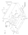
- FIG 2 is an isometric view of the docking station shown in Figure 1a.
- Figure 3 is a front view of apparatus suitable for use as the wall box shown in Figure 1a.
- Figure 4 is a isometric view of a second exemplary embodiment of the wallbox shown in Figure 1a.
- Figure 5 is a rear isometric view of the wallbox shown in Figure 4 attached to the monitor shown in Figure 1.
- FIG. 1 An exemplary docking station system 100 including a docking station 111 in accordance with the present invention is shown in Figure la.
- a portable monitor 102 acquires physiological data signals from a plurality of sensors (not shown), which may include both invasive and non-invasive devices for collecting physiological data from a patient.
- the portable monitor 102 displays the physiological data, and transmits patient data signals to docking station 111 (It will be understood by one skilled in the art that the term "patient data”, as used herein, may refer to the processed information derived from the signals produced by sensors attached to the patient.
- patient data in this sense may include, for example, red, green and blue raster-scan video signals to drive a slave display, or signals to provide status and control information to control auxiliary devices).
- the docking station 111 provides power and communications services to the portable monitor 102 while monitor 102 is mounted on the docking station.
- the mounting mechanism provides for rapid disconnection of the monitor 102 from the docking station 111 (both mechanically and electrically) for transport. Preferably, the disconnection is accomplished in a single step, so that the user can pick up monitor 102 and transport it to another location, without handling any individual cables or connectors.
- docking station 111 includes two modular components.
- the first component is the docking station platform 110.
- Portable monitor 102 may be placed on the docking station platform 110, which may be positioned in the patient area, for example, near the patient's bed or attached to the bedframe.
- Docking station platform 110 provides mechanical support for the portable monitor 102, as well as connections to bedside display 120, power 134, and video display 124.
- Docking Station 111 can also communicate with local area networks (LANs) via couplings 170, 172 and 174. Docking station may provide communications with a computer or intelligent workstation 122, via the networks.
- Docking station 111 provides a simple mechanism to connect portable monitor 102 with several devices and networks without the need to connect individual cables for each device or network. Data and power connectors on the docking station platform 110 and on the case of portable monitor 102 allow simultaneous physical and electrical couplings to be established.
- the second component is a power supply and network box 140 referred to herein as wallbox 140.
- Wallbox 140 is mounted to a wall or other stationary surface.
- Docking station 111 may, include a wallbox 140 coupled to connectors 110c and 110d as shown in Figure 2.
- the wallbox 140 provides power for operating monitor 102 and for charging a battery pack within (or attached to) monitor 102.
- Wallbox 140 also provides communications links to networks and devices, both inside and outside of the room in which docking station 111 is located.
- Portable monitor 102 is a self-contained, standalone monitoring system. Monitor 102 includes all of the processing electronics necessary to process, display and store patient data during transport. In the exemplary embodiment described herein, portable monitor 102 does not include a broad suite of network interfaces; during transport, the exemplary monitor 102 does not have any connections to a central monitoring system or to communications networks. Portable monitor 102 has a rechargeable battery pack for use during transport. Portable monitor is also capable of receiving power from an external power supply. In the first exemplary embodiment of the invention, power is received from wallbox 140 by way of docking station platform 110.
- portable monitor may receive power by either one of two different external methods: (1) via docking station platform 110, and (2) via a Power Source and Network (PSN) box 240 that attaches directly to monitor 102.
- PSN Power Source and Network
- the bedside display 120 may be a slave unit receiving signals for display from docking station 111.
- bedside display 120 may be a conventional bedside patient monitoring unit which receives, stores, processes, displays and transmits medical data.
- the bedside display may be an intelligent workstation 122 with a VGA display and conventional disk storage.
- FIG. 1b shows an isometric view of the first exemplary embodiment of the invention, including a docking station platform 110, a wallbox 140 and monitor assembly 100 of Figure 1a.
- the docking station platform 110 is connected to wallbox 140 by one or more cables 142.
- Portable monitor 102 is mounted on docking station platform 110, providing physical support, power, and communications. Monitor 102 acquires physiological data signals from data acquisition pods 150 and 152 for EKG data for pressure data, respectively.
- a non-invasive blood pressure cartridge 160 and an end tidal CO 2 cartridge 162 collect additional patient data.
- Cartridges 160 and 162, a hardcopy recorder 164 and a battery pack 166 are individually attached to portable monitor 102 for purposes of illustration.
- FIG 2 shows an isometric view of an exemplary docking station platform 110 to which portable monitor 102 may be attached.
- a connector 110a provides data communications couplings to the portable monitor.
- a guide 110b which may be integral with connector 110a as shown in Figure 2, facilitates proper positioning of monitor 102 on docking station platform 110, and assists in maintaining monitor 102 in position while monitor 102 is on docking station platform 110.
- Guide 110b prevents sideways motion between the portable monitor and the docking station.
- Optional guide pins 110h and vertical member 110k may be used in addition to, or in place of, guide 110b to assist in positioning the portable monitor 102 and preventing horizontal motion when monitor 102 is mounted on docking station platform 110.
- a plurality of latches 110j are shown pivotably mounted to the sides of docking station platform 110.
- the latches 110j may be attached to the portable monitor 102 to prevent vertical motion so the portable monitor cannot be accidentally lifted off while mounted to the docking station. It is understood by those skilled in the art that a variety of conventional detachable fasteners may be substituted for latches 110j.
- connector 110a and guide 110b may be separate from one another. There may be multiple connectors 110a to transmit data between portable monitor 102 and docking station 111. Additional mechanical fasteners may be added to improve the stability of the detachable mounting.
- An optional clamp 110e may be used to mount docking station 111 in a variety of locations, including but not limited to: on an intravenous (IV) pole (not shown), a shelf or a bed frame.
- IV intravenous
- a fixed junction box 140 also referred to as a wallbox
- a wallbox 140 suitable for this purpose is shown in Figure 3.
- clamp 110e may be omitted and backplate 110f may be fastened directly to the wallbox 140.
- a separate connector 110g provides power to the portable monitor 102.
- Connector 110d provides data communications links from portable monitor 102 to external devices and networks, when monitor 102 is on docking station platform 110.
- Connector 102d may be a conventional connector which interfaces directly to a local area network (LAN).
- the network may use one of a variety of known LAN protocols, such as carrier sense multiple access with collision detection (CSMA/CD).
- CSMA/CD carrier sense multiple access with collision detection
- the data may be output to a conventional patient monitoring system bedside display 120 and/or to a customized intelligent workstation 122.
- Docking station 111 electrically isolates electrical paths connected to the portable monitor 102.
- Docking station 111 provides 12 volt DC power to the portable monitor 102 via connector 110c and 110g, for operating the monitor when it is mounted on the docking station platform 110.
- Portable monitor 102 includes a battery charger and a nickel-cadmium battery 166 (shown in Figure 1a).
- the battery charger includes connectors and a switch to provide charge to the battery.
- the docking station 111 transmits a signal to the battery charger to activate the switch, so that the battery charger recharges battery 166 while the portable monitor 102 is mounted on the docking station.
- the portable monitor 102 includes alarm processing for the parameters monitored.
- the portable monitor 102 provides an alarm signal to the docking station 111 if any of these alarm conditions is present.
- the docking station 111 includes a separate line within cable 110m for receiving alarm signals, if these signals are generated by the portable monitor while it is mounted on the docking station.
- An alarm output signal is received by docking station platform 110 and transmitted via line 126 to the wallbox 140 for closing relays to activate local alarm devices, such as a light or siren.
- the docking station 111 also receives from the portable monitor 102 a synchronization signal which may be used to trigger a defibrillator. This signal is output from the wallbox 140.
- the wallbox 140 couples the docking station platform 110 to communications links which may include a plurality of local area networks (LANs) or bit serial or parallel-bit data links.
- the wallbox 140 includes buffer amplifiers to condition the docking station output signals for transmission over these LANs.
- the wallbox 140 includes a conventional interface card (not shown) which converts the twisted pair CSMA/CD signal from line 136 (shown in Figure la) to 10 Mbits/second signal suitable for transmission on a Thinnet LAN 174 (referred to as the Unit LAN) operating in accordance with the IEEE 802.3 Type 10-Base-2 standard.
- This Unit LAN 174 connects portable monitor 102 and bedside display 120 with remote stations for transferring patient data.
- the remote stations may be patient monitoring systems or computers.
- This Unit LAN 174 is configured to produce message delays of less than 2 seconds. It is understood by one skilled in the art that a different LAN protocol may be used for Unit LAN 174.
- wallbox 140 provides a direct video connection to a bedside display 120 using a protocol such as the Electronics Industries Association's RS-232-C Interface Standard.
- a protocol such as the Electronics Industries Association's RS-232-C Interface Standard.
- monitor 102 drives bedside display 120, using the RS-232-C link.
- wallbox 140 may include a second conventional interface card (not shown) for interfacing a second LAN 172 (referred to as the Device LAN), which may, for example, be a 10 Mbit/sec. CSMA/CD LAN, to the wallbox 140.
- the Device LAN is used within a patient's room or operating room, or to distribute patient data via a central station.
- the Device LAN provides the main communications path to transfer patient data from the portable monitor 102 to a bedside display 120 within the same room in near real-time. This LAN is configured to maintain short delays and to allow a nominal 200 msec. response time between devices.
- Wallbox 140 includes a third interface card (not shown) and a separate connection 138 which provides a coupling to an additional LAN for connecting input and output devices.
- This additional LAN may use a protocol such as High Level Datalink Control (HDLC) with device polling, for predictable response time.
- This additional LAN is referred to as the Micro LAN 170.
- the Micro LAN is used to connect input and output devices to the portable monitor 102 by way of the docking station 111. These devices (shown in Figure la) may include keyboards 182, pointing devices 184, voice recognition 186 device, a bar code reader 188, a label printer 190, and a remote control 192.
- the remote control 192 may be either wired or infrared (IR). The wired remote control may be more desirable in an operating room (OR) environment, because the OR lights may distort IR control signals.
- the exemplary embodiment includes three distinct LANs for connecting the docking station to remote stations, to local stations (i.e., those within the same room) and to I/O devices
- LANs for connecting the docking station to remote stations, to local stations (i.e., those within the same room) and to I/O devices
- the network configuration may be tailored to protect patients by isolating a device or class of devices on a separate LAN to prevent accidental or unauthorized use. Smaller installations may implement a single local area network within a site to accommodate all of the patient monitoring traffic.
- MVP 130 Eight additional multivendor ports (MVP) 130 are provided to connect serial devices to the portable monitor and remote stations on the network using a known communications interface, e.g., the RS-232 interface standard.
- Wall box 140 includes a demultiplexer 143 and a D/A converter (DAC) 145 which receives digital data from the portable monitor 102 and generates a plurality of analog waveform signals from the digital data. The analog signals are sent to port 129.
- Four analog output ports provide waveform data for transmission to external devices (e.g., displays, recorders).
- existing analog equipment may be connected to the portable monitor (which provides patient data in digital form in the exemplary embodiment) in order to display data collected by the monitor.
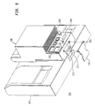
- FIGs 4 and 5 show a second exemplary embodiment of the docking station power supply and network (PSN) box 240.
- wallbox 140 as shown in Figure 3, is mechanically configured to be permanently mounted on a wall
- PSN box 240 supports operation of monitor 102 in either one of two different configurations, shown in respective Figures 4 and 5.
- the PSN box 240 takes over part of the functionality provided by the docking station 111 (i.e., the functionality of the wallbox 140). In the configuration shown in Figure 5, the PSN box 240 completely replaces the docking station 111; i.e., there is no docking station platform 110.
- FIG 4 shows a PSN box 240 in a configuration similar to that shown in Figure 1a.
- PSN box 240 detachably mounts to the wall, bed or some other support on a bracket 260.
- a plate 252 on the back of PSN box 240 slides down into a channel 266 formed between grooves 262 and 264 of bracket 260.
- PSN box 240 includes a plurality of connectors 244, 246, 248, and 250 for receiving respective cables (not shown).
- the cables couple the PSN box 240 to networks and to power, as described above with reference to wallbox 140 as shown in Figure 3.
- Connector 250 receives AC power from the room.
- Connectors 244 and 246 connect PSN Box 240 to the micro LAN 170 (shown in Figure 1a) and the Unit LAN 174 (shown in Figure 1a), respectively.
- a serial port 248 provides an RS-232 link to a bedside display 120 (also shown in Figure 1a).
- the PSN box 240 is coupled to the portable monitor 102 via a cable 268 which connects the PSN box 240 to the docking station platform 110.
- This cable conveys the signals on the connectors 126 through 139 shown in Figure 1a.
- PSN box 240 shown in Figure 4 does not have as many ports as the wallbox 140 shown in Figure 3, it is understood by one skilled in the art that a PSN box may be configured with the same number and types of ports as wallbox 140. Internally, PSN box may include the same configuration of network interface cards and electronics as wall box 140. It is understood by one skilled in the art that PSN box 240 may be constructed with additional interfaces as desired, or the suite of interfaces may be reduced in scope for use in smaller installations, such as the exemplary PSN box 240.
- PSN box 240 is a functional equivalent of wallbox 140.
- PSN box 240 also includes a mounting plate 252 for easy mounting on, and removal from, mounting bracket 260.
- bracket 260 may be permanently attached to a wall or other permanent surface, using conventional fasteners driven through mounting holes 261.
- PSN box 241 also includes an enclosed chimney heat sink 242 on the box.
- FIG 5 shows the same PSN box 240 installed in a different system configuration.
- the PSN box 240 is attached to the back of monitor 102, in a "semi-permanent" manner, as defined below.
- the portable monitor 102 is adapted to receive a battery 166 (as shown in Figure 1b), and monitor 102 has a mounting channel (not shown), similar to channel 266, for receiving the battery.
- PSN box 240 may be attached to portable monitor 102 using the battery mounting channel of the monitor.
- docking station 111 (as shown in Figure la) consists of the PSN box 240, without docking station platform 110.
- PSN box 240 includes a connector (not shown) on the back of plate 252 for supplying power to monitor 102 via its battery connections when PSN box 240 is attached to monitor 102.
- the battery 166 and monitor 102 are configured so that an electrical coupling between them is formed when the battery 166 is mounted on the monitor 102. This same coupling may be replicated on PSN box 240, so that attaching the PSN box 240 to monitor 102 forms an electrical coupling without attaching any cables.
- PSN box 240 is attached to monitor 102 in a "semi-permanent" manner.
- the term "semi-permanent” means that monitor 102 and PSN box 240 may remain attached indefinitely; and there is no predetermined limit on the amount of time required to detach monitor 102 from PSN box 240. Separating monitor 102 from PSN box 240 may take anywhere from several seconds to a few minutes. This amount of time may be unacceptable in an emergency, but does not generally present a problem for routine operations.
- the semi-permanent attachment technique is used for a monitor 102 which is not allocated by the user as a transport monitor. The monitor 102 is used in the same fashion as a fixed location monitoring system. This semi-permanent attachment may be contrasted to the detachable mounting means on docking station platform 110. Monitor 102 may be removed from docking station platform 110 within seconds, which is especially advantageous for transport in an emergency situation.
- the docking station platform 110 When the PSN box 240 is attached directly to monitor 102, the docking station platform 110 is not used.
- the assembly 200 consisting of the monitor 102 and the PSN box 240 may be placed on a table, a stand, or other suitable surface.
- the combination 200 of the monitor 102 and PSN box 240 may be considered a tethered monitor 200, which may be moved subject to constraints due to the power cord (not shown) and data communications cables (not shown).
- PSN box 240 may be connected directly to the monitor 102.
- a coupling device 270 provides circuit paths between the connectors 272 and 274 on the bottom of portable monitor 102 and the bottom of PSN box 240, respectively.
- coupling device 270 includes the same connectors 110a and 110g that are used on docking station platform 110, for the interface with connector 272. Electrically, coupling device 270 performs the same functions as cable 142 and connectors 110a and 110g, as shown in Figure 2. In addition, coupling device 270 provides structural support to prevent accidental separation of PSN box 240 from monitor 102. The semi-permanent attachment is formed using fasteners 276 which may, for example, be screws. The additional mechanical support provided by coupling device 270 is important because the assembly 200 may be jostled around accidentally. Assembly 200 rests on a surface, and may not be firmly attached to any structure.
- PSN box 240 provides advantageous flexibility. When PSN box 240 is coupled to monitor 102 as shown in Figure 5, the resulting combination provides the same functionality as a conventional bedside display unit in a compact form; ports 244 and 246 for interfacing with communications networks 170 and 174 and a coupling 250 for receiving power are provided.
- the PSN box 240 provides the network interface capability that is typically desired in a fixed location monitoring system, and is typically absent in transportable monitoring systems in the prior art. A separate docking station platform 110 is not required, which may reduce costs. This type of configuration may be desirable if the user does not intend to use the monitor 102 for patient transport under emergency conditions.
- PSN box 240 essentially converts a reduced function monitoring system (i.e., a system without network interface capability) into a full function monitoring system with network interfaces.
- Portable monitor 102 may now be mounted on, or removed from, docking station platform 110 in substantially less than a minute. Monitor 102 may now be used as a bedside monitor while mounted on docking station platform 110, and as a transport monitor when removed from platform 110.
- the user has transformed the semi-permanent attachment into a modular system, with the capability to pick up the monitor and transport it, substantially avoiding any delays to configure the apparatus for transport.
Abstract
Description
Claims (26)
- A docking station adapted for use in a patient monitoring system wherein the patient may be located within a given patient monitoring area, or transported out of said area, said system including a communications network (170, 172, 174) located in a relatively fixed position within said patient monitoring area, and a portable patient monitor (102) that is adapted to be coupled to a plurality of sensors to substantially continuously receive and display patient data signals provided by the sensors, CHARACTERIZED IN THAT
the docking station (111) includes a platform (110) comprising:(a) mounting means (110, 110b, 110h, 110j, 110k) for detachably coupling the portable monitor to the docking station so as to physically support said portable monitor (102) when it's mounted to the docking station;(b) means (110a) from receiving patient data from the portable monitor when the portable monitor (102) is coupled to the docking station (111); and(c) means (110d) for transferring the received patient data to the communications network when the portable monitor is coupled to the docking station (111). - A docking station in accordance with claim 1, further CHARACTERIZED IN THAT said docking station (111) includes means (132, 140, 172) for transferring the patient data to a computer workstation (122) by way of the communications network when the portable monitor (102) is coupled to the docking station platform (110).
- A docking station in accordance with claim 1, further CHARACTERIZED BY means (110c, 110g) for providing power from the docking station (111) to the portable monitor (102) when the portable monitor is coupled to the docking station.
- A docking station in accordance with claim 2, CHARACTERIZED IN THAT the mounting means include:at least one latch (110j) which secures the portable monitor to the docking station, preventing vertical motion between the docking station and the portable monitor while the portable monitor is coupled to the docking station; andat least one vertical pin (110h) which prevents horizontal motion between the portable monitor and the docking station while the portable monitor is coupled to the docking station.
- A docking station in accordance with claim 2, CHARACTERIZED IN THAT the mounting means include:at least one latch (110j) which prevents the portable monitor from being lifted off of the docking station while the portable monitor is coupled to the docking station; anda vertically mounted electrical connector (110a) which prevents sideways motion between the portable monitor and the docking station while the portable monitor is coupled to the docking station.
- A docking station in accordance with claim 1, CHARACTERIZED IN THAT said docking station includes:a plurality of serial ports (MVP(8)) which receive input signals from a respective plurality of input devices;means (130) for coupling the serial ports to the portable monitor when the portable monitor is coupled to the docking station and for transmitting the input signals to the portable monitor (102).
- A docking station in accordance with claim 1, CHARACTERIZED IN THAT the portable monitor has a battery and a battery charger (166), and the docking station includes means (110g) for causing the battery charger to charge the battery when the portable monitor is coupled to the docking station.
- A docking station in accordance with claim 7, CHARACTERIZED IN THAT the portable monitor (102) has means (266) for detachably mounting the battery (166) to the portable monitor (102), and said docking station includes:
a power supply and network (PSN) box (240), comprising:means (270) for electrically coupling the PSN box (240) to the portable monitor (102), andmeans for attaching the PSN box (240) to the battery mounting means (266) of the portable monitor when the battery (166) is not mounted on the battery mounting means. - A docking station in accordance with claim 1, further CHARACTERIZED BY:means (110m) for receiving an alarm signal from the portable monitor when the portable monitor (102) is coupled to the docking station (110); andmeans (126) responsive to the alarm signal receiving means for transmitting an alarm activation signal to an alarm device.
- A docking station in accordance with claim 1 CHARACTERIZED IN THAT a plurality of input devices (182-192) are coupled to the communications network (170), the docking station further comprising means (MICROLAN, 138) for transferring input signals from the communications network to the portable monitor when the portable monitor is coupled to the docking station.
- A docking station in accordance with claim 10, CHARACTERIZED IN THAT the plurality of input devices includes a voice recognition device (186).
- A docking station in accordance with claim 10, CHARACTERIZED IN THAT the plurality of input devices includes a bar code reader (188).
- A docking station in accordance with claim 10, CHARACTERIZED IN THAT the plurality of input devices includes a remote control device (192) which controls operation of the portable monitor (102).
- A docking station in accordance with claim 10, CHARACTERIZED IN THAT the plurality of input devices includes a keyboard (182).
- A docking station in accordance with claim 1 CHARACTERIZED IN THAT a plurality of output devices (120-124) are coupled to the communications network (140), the docking station further comprising means (138, 132, 139) for transferring output signals from the portable monitor to the communications network when the portable monitor is coupled to the docking station.
- A docking station in accordance with claim 15, CHARACTERIZED IN THAT the plurality of output devices includes a label printer (190).
- A docking station in accordance with claim 1, further CHARACTERIZED IN THAT said docking station (111) includes:a demultiplexer (143 of 140) which separates the patient data received from the portable monitor (102) into a plurality of output signals;means (145) for converting the plurality of output signals into a plurality of analog signals; andmeans (128, 129) for transmitting the plurality of analog signals to a plurality of analog output devices.
- A docking station in accordance with claim 1, CHARACTERIZED BY means (137) for generating and transmitting a synchronization signal to a defibrillator.
- A docking station in accordance with claim 1, CHARACTERIZED BY means (110e) for attaching the docking station platform (110) to an intravenous pole.
- A docking station in accordance with claim 1, CHARACTERIZED BY means (110e) for attaching the docking station platform (110) to the patient's bed.
- A docking station in accordance with claim 1, CHARACTERIZED BY means (132, Device LAN of 140) for transferring the patient data between the portable monitor (102) and a plurality of remote stations (120-124) by way of the communications network (172) when the portable monitor (102) is coupled to the docking station (111).
- A system for substantially continuously acquiring and displaying medical data from a plurality of sensors attached to a patient, adapted for use in a room which includes a non-portable communications network (140), a portable monitor adapted to be coupled to the plurality of sensors, which substantially continuously receives, processes and displays patient data signals from the plurality of sensors; and a docking station for transferring patient data to the communications network, the system CHARACTERIZED IN THAT:
the docking station (111) includes a docking station platform (110) for physically and electronically supporting the portable monitor, said platform (110) comprising:means (110, 110j, 110b) for detachably mounting the portable monitor on the docking station (110),means (110c, 110d) for electronically coupling the docking station to a power source and to the communications network, andmeans (110a) for substantially continuously transferring patient data received from the portable monitor (102) to the communications network. - A system in accordance with claim 22, CHARACTERIZED IN THAT said docking station (111) includes:
a power supply and network (PSN) box (240), comprising:(1) attaching means for attaching the portable monitor (102) to the PSN box (240),(2) means (270) for receiving patient data from the portable monitor directly when the portable monitor is attached to the PSN box, and means (268) for receiving patient data from the portable monitor by way of the docking station platform (110) when the portable monitor is mounted on the docking station platform, and(3) means (244, 246) for transferring the received patient data to the communications network. - A system in accordance with claim 23, CHARACTERIZED BY:means (110c, 110g) for providing power from the PSN box to the portable monitor by way of the docking station platform (110) when the portable monitor is mounted on the docking station platform; andmeans (250) for providing power from the PSN box to the portable monitor directly when the portable monitor is attached to the PSN box.
- A system in accordance with claim 23, CHARACTERIZED IN THAT the attaching means include means (270) for electrically coupling the portable monitor to the PSN box.
- A system in accordance with claim 23, CHARACTERIZED IN THAT the portable monitor has a battery (166) and means (similar to 266) for mounting the battery on the portable monitor, andwherein the attaching means of the PSN box include means (252) for attaching the PSN box to the battery mounting means of the portable monitor when the battery is not mounted on the battery mounting means.
Applications Claiming Priority (3)
| Application Number | Priority Date | Filing Date | Title |
|---|---|---|---|
| US98941092A | 1992-12-11 | 1992-12-11 | |
| US989410 | 1992-12-11 | ||
| PCT/US1993/011711 WO1994014128A2 (en) | 1992-12-11 | 1993-12-02 | Docking station for a patient monitoring system |
Publications (2)
| Publication Number | Publication Date |
|---|---|
| EP0673530A1 EP0673530A1 (en) | 1995-09-27 |
| EP0673530B1 true EP0673530B1 (en) | 1998-05-27 |
Family
ID=25535089
Family Applications (1)
| Application Number | Title | Priority Date | Filing Date |
|---|---|---|---|
| EP94909412A Expired - Lifetime EP0673530B1 (en) | 1992-12-11 | 1993-12-02 | Docking station for a patient monitoring system |
Country Status (7)
| Country | Link |
|---|---|
| US (1) | US6183417B1 (en) |
| EP (1) | EP0673530B1 (en) |
| JP (1) | JP3466612B2 (en) |
| AT (1) | ATE166734T1 (en) |
| DE (1) | DE69318850T2 (en) |
| DK (1) | DK0673530T3 (en) |
| WO (1) | WO1994014128A2 (en) |
Families Citing this family (166)
| Publication number | Priority date | Publication date | Assignee | Title |
|---|---|---|---|---|
| US5685314A (en) * | 1992-12-11 | 1997-11-11 | Siemens Medical Systems, Inc. | Auxiliary docking station for a patient monitoring system |
| GB2288922B (en) | 1994-04-25 | 1998-04-01 | John Edward Mcgrath | Patient monitoring apparatus |
| US5579775A (en) * | 1994-10-20 | 1996-12-03 | Hewlett-Packard Company | Dynamic control of a patient monitoring system |
| US5687734A (en) * | 1994-10-20 | 1997-11-18 | Hewlett-Packard Company | Flexible patient monitoring system featuring a multiport transmitter |
| US5640953A (en) * | 1995-03-09 | 1997-06-24 | Siemens Medical Systems, Inc. | Portable patient monitor reconfiguration system |
| AU1371199A (en) * | 1997-10-31 | 1999-05-24 | Mercury Diagnostics Inc. | Analyte concentration information collection and communication s ystem |
| US7612999B2 (en) * | 1998-09-18 | 2009-11-03 | Flo Healthcare Solutions, Llc | Mobile clinical workstation |
| US6407335B1 (en) * | 1999-11-19 | 2002-06-18 | Alaris Medical Systems, Inc. | Medical device interface system |
| US6442432B2 (en) | 1999-12-21 | 2002-08-27 | Medtronic, Inc. | Instrumentation and software for remote monitoring and programming of implantable medical devices (IMDs) |
| CN1200641C (en) * | 2000-11-20 | 2005-05-11 | 美国西门子医疗解决公司 | Electrically isolated power and signal coupler system for patient connected device |
| US6524240B1 (en) * | 2000-11-22 | 2003-02-25 | Medwave, Inc. | Docking station for portable medical devices |
| US6594146B2 (en) | 2000-12-26 | 2003-07-15 | Ge Medical Systems Information Technologies, Inc. | Docking station for patient monitor or other electronic device |
| US7154397B2 (en) | 2001-08-03 | 2006-12-26 | Hill Rom Services, Inc. | Patient point-of-care computer system |
| US6773397B2 (en) | 2001-10-11 | 2004-08-10 | Draeger Medical Systems, Inc. | System for processing signal data representing physiological parameters |
| US8775196B2 (en) | 2002-01-29 | 2014-07-08 | Baxter International Inc. | System and method for notification and escalation of medical data |
| US10173008B2 (en) | 2002-01-29 | 2019-01-08 | Baxter International Inc. | System and method for communicating with a dialysis machine through a network |
| US6865418B2 (en) | 2002-03-04 | 2005-03-08 | Medtronic Physio-Control Corp. | Docking station for defibrillator |
| US6850788B2 (en) | 2002-03-25 | 2005-02-01 | Masimo Corporation | Physiological measurement communications adapter |
| US7534211B2 (en) | 2002-03-29 | 2009-05-19 | Sonosite, Inc. | Modular apparatus for diagnostic ultrasound |
| US7338443B1 (en) | 2002-04-29 | 2008-03-04 | Tucker Peter L | Secure patient data recorder for recording monitored vital sign data |
| US8234128B2 (en) | 2002-04-30 | 2012-07-31 | Baxter International, Inc. | System and method for verifying medical device operational parameters |
| US20040186357A1 (en) * | 2002-08-20 | 2004-09-23 | Welch Allyn, Inc. | Diagnostic instrument workstation |
| US20050288571A1 (en) * | 2002-08-20 | 2005-12-29 | Welch Allyn, Inc. | Mobile medical workstation |
| TW575226U (en) * | 2002-12-02 | 2004-02-01 | Tatung Co | Brightness switching control device between portable device and connection seat |
| US7140546B1 (en) * | 2002-12-12 | 2006-11-28 | Symbol Technologies, Inc. | Battery pack with integrated human interface devices |
| US7591786B2 (en) * | 2003-01-31 | 2009-09-22 | Sonosite, Inc. | Dock for connecting peripheral devices to a modular diagnostic ultrasound apparatus |
| US20060142808A1 (en) * | 2003-04-22 | 2006-06-29 | Christopher Pearce | Defibrillator/monitor system having a pod with leads capable of wirelessly communicating |
| US9010645B2 (en) | 2003-06-13 | 2015-04-21 | Michael Arnouse | Portable computing system and portable computer for use with same |
| EP1665479A4 (en) | 2003-08-21 | 2008-01-23 | Hill Rom Services Inc | Plug and receptacle having wired and wireless coupling |
| CN1871611A (en) | 2003-11-12 | 2006-11-29 | 德雷格医疗系统股份有限公司 | Modular medical care system |
| WO2005050523A2 (en) * | 2003-11-13 | 2005-06-02 | Draeger Medical Systems, Inc | A processing device and display system |
| WO2005058416A1 (en) * | 2003-12-17 | 2005-06-30 | Medtronic Physio-Control Corp. | An external defibrillator with power and battery sharing capabilities with a pod |
| US10413742B2 (en) | 2008-03-05 | 2019-09-17 | Physio-Control, Inc. | Defibrillator patient monitoring pod |
| US8600491B2 (en) * | 2003-12-17 | 2013-12-03 | Physio-Control, Inc. | Defibrillator patient monitoring pod |
| US7957798B2 (en) * | 2003-12-17 | 2011-06-07 | Physio-Control, Inc. | Defibrillator/monitor system having a pod with leads capable of wirelessly communicating |
| US20050277873A1 (en) * | 2004-05-27 | 2005-12-15 | Janice Stewart | Identification information recognition system for a medical device |
| US8961461B2 (en) | 2004-05-27 | 2015-02-24 | Baxter International Inc. | Multi-state alarm system for a medical pump |
| US7927313B2 (en) * | 2004-05-27 | 2011-04-19 | Baxter International Inc. | Medical device configuration based on recognition of identification information |
| US7852208B2 (en) | 2004-08-02 | 2010-12-14 | Hill-Rom Services, Inc. | Wireless bed connectivity |
| US7319386B2 (en) * | 2004-08-02 | 2008-01-15 | Hill-Rom Services, Inc. | Configurable system for alerting caregivers |
| US20060094935A1 (en) * | 2004-10-20 | 2006-05-04 | Coulbourn Instruments, L.L.C. | Portable psychophysiology system and method of use |
| EP1805607A2 (en) * | 2004-10-25 | 2007-07-11 | Draeger Medical Systems, Inc. | A portable device configuration system |
| US7339475B2 (en) * | 2004-11-10 | 2008-03-04 | Black & Decker Inc. | Portable alarm system |
| US20060149321A1 (en) * | 2004-12-30 | 2006-07-06 | Merry Randy L | Medical device information system |
| AU2006204886B2 (en) * | 2005-01-13 | 2011-08-04 | Welch Allyn, Inc. | Vital signs monitor |
| US20070016443A1 (en) * | 2005-07-13 | 2007-01-18 | Vitality, Inc. | Medication compliance systems, methods and devices with configurable and adaptable escalation engine |
| US20100328099A1 (en) * | 2005-07-13 | 2010-12-30 | Vitality, Inc. | Night Light With Embedded Cellular Modem |
| US20100270257A1 (en) * | 2005-07-13 | 2010-10-28 | Vitality, Inc. | Medicine Bottle Cap With Electronic Embedded Curved Display |
| US20090134181A1 (en) * | 2005-07-13 | 2009-05-28 | Vitality, Inc. | Medication dispenser with automatic refill |
| US10299668B2 (en) | 2005-10-21 | 2019-05-28 | Physio-Control, Inc. | Laryngoscope with handle-grip activated recording |
| US8666488B2 (en) | 2006-02-06 | 2014-03-04 | Physio-Control, Inc. | Post-download patient data protection in a medical device |
| US20070185545A1 (en) * | 2006-02-06 | 2007-08-09 | Medtronic Emergency Response Systems, Inc. | Post-download patient data protection in a medical device |
| US7873409B2 (en) * | 2006-05-15 | 2011-01-18 | General Electric Company | Invasive cardiology digital signal amplifier and acquisition device |
| AU2007257311A1 (en) * | 2006-06-02 | 2007-12-13 | Cbb International Pty Ltd | A monitoring system |
| CN101610735B (en) | 2006-06-28 | 2015-07-01 | 美敦力Af卢森堡公司 | Methods and systems for thermally-induced renal neuromodulation |
| US9161696B2 (en) | 2006-09-22 | 2015-10-20 | Masimo Corporation | Modular patient monitor |
| US8840549B2 (en) * | 2006-09-22 | 2014-09-23 | Masimo Corporation | Modular patient monitor |
| EP2097963B1 (en) * | 2006-12-28 | 2019-05-15 | Draeger Medical Systems, Inc. | An electronic device identification system |
| US20080234555A1 (en) * | 2007-03-23 | 2008-09-25 | Stryker Corporation | Patient care system |
| US20090005651A1 (en) * | 2007-06-27 | 2009-01-01 | Welch Allyn, Inc. | Portable systems, devices and methods for displaying varied information depending on usage circumstances |
| US8461968B2 (en) * | 2007-08-29 | 2013-06-11 | Hill-Rom Services, Inc. | Mattress for a hospital bed for use in a healthcare facility and management of same |
| US7868740B2 (en) | 2007-08-29 | 2011-01-11 | Hill-Rom Services, Inc. | Association of support surfaces and beds |
| US8082160B2 (en) | 2007-10-26 | 2011-12-20 | Hill-Rom Services, Inc. | System and method for collection and communication of data from multiple patient care devices |
| US20090124868A1 (en) * | 2007-11-09 | 2009-05-14 | Peter Andrew Barnett | Lightweight portable trauma treatment and patient monitoring device |
| US10235323B2 (en) | 2008-02-13 | 2019-03-19 | Michael Arnouse | Portable computing system and portable computer for use with same |
| USRE49124E1 (en) | 2008-02-13 | 2022-07-05 | Arnouse Digital Devices Corp. | Mobile data center |
| US11113228B2 (en) | 2008-02-13 | 2021-09-07 | Arnouse Digital Devices Corporation | Portable computing system and portable computer for use with same |
| US8384526B2 (en) | 2008-02-22 | 2013-02-26 | Hill-Rom Services, Inc. | Indicator apparatus for healthcare communication system |
| US7855530B2 (en) * | 2008-02-25 | 2010-12-21 | Stinger Industries, Llc | Battery charging system and method of reducing variation in battery charging cycle count |
| US7782607B2 (en) * | 2008-02-25 | 2010-08-24 | Stinger Industries LLC | Mobile workstation having power system with removable battery configured for drop-in engagement therewith |
| US7830668B2 (en) * | 2008-02-25 | 2010-11-09 | Stinger Industries LLC | Power supply unit for mobile workstation and method |
| US8227943B2 (en) * | 2008-02-25 | 2012-07-24 | Lee Melvin Harbin | Power system retrofit kit for mobile workstation and retrofit method |
| US7800255B2 (en) * | 2008-02-25 | 2010-09-21 | Stinger Industries LLC | Power system for mobile workstation and method |
| US8169191B2 (en) * | 2008-02-25 | 2012-05-01 | Werthman Dean A | System for use in gathering or processing data in a healthcare facility having fleet of mobile workstations |
| US8160727B2 (en) * | 2008-02-25 | 2012-04-17 | Gary Coonan | Mobile workstation control system configured for power system and peripheral device control |
| US8775828B2 (en) * | 2008-02-25 | 2014-07-08 | Gary Coonan | Power control system for mobile workstation and method |
| CN101569537B (en) * | 2008-04-29 | 2014-07-09 | Ge医疗系统环球技术有限公司 | Docking station and ultrasonic diagnosis system |
| EP2285269B1 (en) * | 2008-04-29 | 2012-11-07 | Oridion Medical 1987 Ltd. | Wireless capnography |
| US20100010320A1 (en) * | 2008-07-07 | 2010-01-14 | Perkins David G | Mobile medical workstation and a temporarily associating mobile computing device |
| US10089443B2 (en) | 2012-05-15 | 2018-10-02 | Baxter International Inc. | Home medical device systems and methods for therapy prescription and tracking, servicing and inventory |
| US8057679B2 (en) | 2008-07-09 | 2011-11-15 | Baxter International Inc. | Dialysis system having trending and alert generation |
| US8123694B2 (en) * | 2008-07-18 | 2012-02-28 | Welch Allyn, Inc. | Electro pneumatic interface for blood pressure system |
| US8554579B2 (en) | 2008-10-13 | 2013-10-08 | Fht, Inc. | Management, reporting and benchmarking of medication preparation |
| DE102009039953A1 (en) * | 2009-08-28 | 2011-03-03 | Bernd Beck | Measurement data converter for a patient monitoring system |
| US9153112B1 (en) | 2009-12-21 | 2015-10-06 | Masimo Corporation | Modular patient monitor |
| US8779924B2 (en) * | 2010-02-19 | 2014-07-15 | Hill-Rom Services, Inc. | Nurse call system with additional status board |
| US8618918B2 (en) | 2010-04-09 | 2013-12-31 | Hill-Rom Services, Inc. | Patient support, communication, and computing apparatus including movement of the support and connection to the hospital network |
| JP5661180B2 (en) | 2010-06-25 | 2015-01-28 | ヴァリアン メディカル システムズ インコーポレイテッド | Remodeling kit and remodeling method for current portable or movable analog X-ray imaging apparatus and X-ray diagnostic apparatus equipped with the remodeling kit to enable application of digital X-ray imaging |
| EP3449856B1 (en) | 2010-10-25 | 2023-06-28 | Medtronic Ardian Luxembourg S.à.r.l. | Device for evaluation and feedback of neuromodulation treatment |
| FR2968536B1 (en) * | 2010-12-13 | 2013-01-11 | Coactive Technologies Inc | CONTROL CONSOLE FOR A MEDICAL DEVICE, THE CONSOLE MAY BE FIXED TO A RAIL |
| US9629566B2 (en) | 2011-03-11 | 2017-04-25 | Spacelabs Healthcare Llc | Methods and systems to determine multi-parameter managed alarm hierarchy during patient monitoring |
| US9943269B2 (en) | 2011-10-13 | 2018-04-17 | Masimo Corporation | System for displaying medical monitoring data |
| EP3584799B1 (en) | 2011-10-13 | 2022-11-09 | Masimo Corporation | Medical monitoring hub |
| US10307111B2 (en) | 2012-02-09 | 2019-06-04 | Masimo Corporation | Patient position detection system |
| US10149616B2 (en) | 2012-02-09 | 2018-12-11 | Masimo Corporation | Wireless patient monitoring device |
| EP4094701A1 (en) * | 2012-03-04 | 2022-11-30 | Medtronic Ireland Manufacturing Unlimited Company | Generator assemblies for neuromodulation therapy |
| US9510777B2 (en) | 2012-03-08 | 2016-12-06 | Medtronic Ardian Luxembourg S.A.R.L. | Monitoring of neuromodulation using biomarkers |
| US10101769B2 (en) | 2012-04-10 | 2018-10-16 | Michael Arnouse | Mobile data center |
| DE102012008301A1 (en) * | 2012-04-26 | 2013-10-31 | Paul Hartmann Ag | Fastening device for a negative pressure therapy device |
| US9457197B2 (en) | 2012-05-08 | 2016-10-04 | Physio-Control, Inc. | Utility module system |
| US9411934B2 (en) | 2012-05-08 | 2016-08-09 | Hill-Rom Services, Inc. | In-room alarm configuration of nurse call system |
| CA2873755A1 (en) * | 2012-05-15 | 2013-11-21 | Spacelabs Healthcare, Llc | Configurable, portable patient monitoring system |
| WO2013185176A1 (en) * | 2012-06-12 | 2013-12-19 | C. Rafin & Co Pty Ltd | A method and apparatus for facilitating the management of health and security |
| US10303852B2 (en) | 2012-07-02 | 2019-05-28 | Physio-Control, Inc. | Decision support tool for use with a medical monitor-defibrillator |
| US9749232B2 (en) | 2012-09-20 | 2017-08-29 | Masimo Corporation | Intelligent medical network edge router |
| US9314159B2 (en) | 2012-09-24 | 2016-04-19 | Physio-Control, Inc. | Patient monitoring device with remote alert |
| US9539155B2 (en) | 2012-10-26 | 2017-01-10 | Hill-Rom Services, Inc. | Control system for patient support apparatus |
| NZ716476A (en) | 2012-10-26 | 2018-10-26 | Baxter Corp Englewood | Improved work station for medical dose preparation system |
| KR101695119B1 (en) | 2012-10-26 | 2017-01-23 | 백스터 코포레이션 잉글우드 | Improved image acquisition for medical dose preparation system |
| US10085662B2 (en) * | 2012-10-30 | 2018-10-02 | The United States Of America As Represented By The Administrator Of The National Aeronautics And Space Administration | Device and method for digital-to-analog transformations and reconstructions of multi-channel electrocardiograms |
| JP6027446B2 (en) * | 2013-01-08 | 2016-11-16 | 日本光電工業株式会社 | Biological information monitor system |
| US9299240B2 (en) | 2013-02-27 | 2016-03-29 | Welch Allyn, Inc. | Anti-loss for medical devices |
| JP6058426B2 (en) * | 2013-02-27 | 2017-01-11 | フクダ電子株式会社 | Biological information monitor and its carrier |
| JP5961126B2 (en) | 2013-03-04 | 2016-08-02 | 日本光電工業株式会社 | Biological information monitor system |
| EP4233991A1 (en) | 2013-03-15 | 2023-08-30 | Medtronic Ardian Luxembourg S.à.r.l. | Controlled neuromodulation systems |
| US10474808B2 (en) | 2013-03-29 | 2019-11-12 | Hill-Rom Services, Inc. | Hospital bed compatibility with third party application software |
| US10987026B2 (en) | 2013-05-30 | 2021-04-27 | Spacelabs Healthcare Llc | Capnography module with automatic switching between mainstream and sidestream monitoring |
| US9326816B2 (en) | 2013-08-30 | 2016-05-03 | Medtronic Ardian Luxembourg S.A.R.L. | Neuromodulation systems having nerve monitoring assemblies and associated devices, systems, and methods |
| US9339332B2 (en) | 2013-08-30 | 2016-05-17 | Medtronic Ardian Luxembourg S.A.R.L. | Neuromodulation catheters with nerve monitoring features for transmitting digital neural signals and associated systems and methods |
| US9830424B2 (en) | 2013-09-18 | 2017-11-28 | Hill-Rom Services, Inc. | Bed/room/patient association systems and methods |
| US10832818B2 (en) | 2013-10-11 | 2020-11-10 | Masimo Corporation | Alarm notification system |
| US10433902B2 (en) | 2013-10-23 | 2019-10-08 | Medtronic Ardian Luxembourg S.A.R.L. | Current control methods and systems |
| US10405757B2 (en) | 2014-02-25 | 2019-09-10 | Icu Medical, Inc. | Patient monitoring system with gatekeeper signal |
| US10610292B2 (en) | 2014-04-25 | 2020-04-07 | Medtronic Ardian Luxembourg S.A.R.L. | Devices, systems, and methods for monitoring and/or controlling deployment of a neuromodulation element within a body lumen and related technology |
| JP2017525032A (en) | 2014-06-30 | 2017-08-31 | バクスター・コーポレーション・イングルウッドBaxter Corporation Englewood | Managed medical information exchange |
| WO2016033543A1 (en) | 2014-08-28 | 2016-03-03 | Medtronic Ardian Luxembourg S.A.R.L. | Methods for assessing efficacy of renal neuromodulation and associated systems and devices |
| US11107574B2 (en) | 2014-09-30 | 2021-08-31 | Baxter Corporation Englewood | Management of medication preparation with formulary management |
| US11575673B2 (en) | 2014-09-30 | 2023-02-07 | Baxter Corporation Englewood | Central user management in a distributed healthcare information management system |
| EP3791817A1 (en) | 2014-10-01 | 2021-03-17 | Medtronic Ardian Luxembourg S.à.r.l. | Systems for evaluating neuromodulation therapy via hemodynamic responses |
| EP3937116A1 (en) | 2014-12-05 | 2022-01-12 | Baxter Corporation Englewood | Dose preparation data analytics |
| US10667736B2 (en) | 2014-12-17 | 2020-06-02 | Medtronic Ardian Luxembourg S.A.R.L. | Systems and methods for assessing sympathetic nervous system tone for neuromodulation therapy |
| CN107533578B (en) | 2014-12-18 | 2021-04-02 | 德尔格制造股份两合公司 | Intelligent patient monitor base |
| CN107209812B (en) * | 2015-02-13 | 2021-08-10 | 皇家飞利浦有限公司 | Portable medical support system with auxiliary viewing mode and method of operating the same |
| MX2017011124A (en) * | 2015-03-03 | 2017-11-28 | Koninklijke Philips Nv | Modular medical system for patient monitoring and electrical therapy delivery. |
| JP2018507487A (en) | 2015-03-03 | 2018-03-15 | バクスター・コーポレーション・イングルウッドBaxter Corporation Englewood | Pharmacy workflow management with alert integration |
| CN116206744A (en) | 2015-06-25 | 2023-06-02 | 甘布罗伦迪亚股份公司 | Medical device systems and methods with distributed databases |
| CA2996196A1 (en) | 2015-08-31 | 2017-03-09 | Masimo Corporation | Wireless patient monitoring systems and methods |
| EP3364860A4 (en) | 2015-10-19 | 2019-09-18 | ICU Medical, Inc. | Hemodynamic monitoring system with detachable display unit |
| US11166628B2 (en) | 2016-02-02 | 2021-11-09 | Physio-Control, Inc. | Laryngoscope with handle-grip activated recording |
| US10582981B2 (en) | 2016-02-02 | 2020-03-10 | Stryker Corporation | Accessory support and coupling systems for an accessory support |
| US10893988B2 (en) | 2016-05-26 | 2021-01-19 | Stryker Corporation | Patient support systems and methods for docking, transporting, sterilizing, and storing patient support decks |
| WO2017214033A1 (en) | 2016-06-07 | 2017-12-14 | Stryker Corporation | Thermal control system |
| US10617302B2 (en) | 2016-07-07 | 2020-04-14 | Masimo Corporation | Wearable pulse oximeter and respiration monitor |
| EP3525661A1 (en) | 2016-10-13 | 2019-08-21 | Masimo Corporation | Systems and methods for patient fall detection |
| US10231784B2 (en) | 2016-10-28 | 2019-03-19 | Medtronic Ardian Luxembourg S.A.R.L. | Methods and systems for optimizing perivascular neuromodulation therapy using computational fluid dynamics |
| US10905520B2 (en) | 2016-11-11 | 2021-02-02 | Stryker Corporation | Autonomous accessory support for transporting a medical accessory |
| JP6294947B2 (en) * | 2016-12-07 | 2018-03-14 | フクダ電子株式会社 | Biological information monitor and its carrier |
| AU2017381172A1 (en) | 2016-12-21 | 2019-06-13 | Gambro Lundia Ab | Medical device system including information technology infrastructure having secure cluster domain supporting external domain |
| EP3563382A1 (en) * | 2016-12-30 | 2019-11-06 | Televic Healthcare NV | Connection unit for connecting a plurality of medical devices and system comprising same |
| US11123014B2 (en) | 2017-03-21 | 2021-09-21 | Stryker Corporation | Systems and methods for ambient energy powered physiological parameter monitoring |
| US10818392B1 (en) | 2017-08-10 | 2020-10-27 | Enovate Medical, Llc | Battery and workstation monitoring system and display |
| US11007102B2 (en) | 2017-08-22 | 2021-05-18 | Stryker Corporation | Patient transport system |
| US10646170B2 (en) * | 2017-12-20 | 2020-05-12 | Drägerwerk AG & Co. KGaA | Rotating docking station |
| WO2019204368A1 (en) | 2018-04-19 | 2019-10-24 | Masimo Corporation | Mobile patient alarm display |
| US11633120B2 (en) | 2018-09-04 | 2023-04-25 | Medtronic Ardian Luxembourg S.A.R.L. | Systems and methods for assessing efficacy of renal neuromodulation therapy |
| US11229568B2 (en) | 2018-09-30 | 2022-01-25 | Hill-Rom Services, Inc. | Mattress support for adding hospital bed functionality to an in-home bed |
| US11367535B2 (en) | 2018-09-30 | 2022-06-21 | Hill-Rom Services, Inc. | Patient care system for a home environment |
| US11357682B2 (en) | 2018-09-30 | 2022-06-14 | Hill-Rom Services, Inc. | Structures for causing movement of elements of a bed |
| US11241347B2 (en) | 2018-10-01 | 2022-02-08 | Hill-Rom Services, Inc. | Mattress support for adding hospital bed modular control system for upgrading a bed to include movable components |
| US11400001B2 (en) | 2018-10-01 | 2022-08-02 | Hill-Rom Services, Inc. | Method and apparatus for upgrading a bed to include moveable components |
| US11911325B2 (en) | 2019-02-26 | 2024-02-27 | Hill-Rom Services, Inc. | Bed interface for manual location |
| US10959534B2 (en) | 2019-02-28 | 2021-03-30 | Hill-Rom Services, Inc. | Oblique hinged panels and bladder apparatus for sleep disorders |
| US11920361B2 (en) | 2020-03-27 | 2024-03-05 | Physio-Control, Inc. | Medical device docking station |
| USD980091S1 (en) | 2020-07-27 | 2023-03-07 | Masimo Corporation | Wearable temperature measurement device |
| USD974193S1 (en) | 2020-07-27 | 2023-01-03 | Masimo Corporation | Wearable temperature measurement device |
| USD1000975S1 (en) | 2021-09-22 | 2023-10-10 | Masimo Corporation | Wearable temperature measurement device |
Family Cites Families (24)
| Publication number | Priority date | Publication date | Assignee | Title |
|---|---|---|---|---|
| DE6948919U (en) | 1969-12-16 | 1970-03-19 | Bbc Brown Boveri & Cie | WALL MONITOR FOR PATIENT MONITORING |
| US3940742A (en) * | 1973-08-06 | 1976-02-24 | Medical Monitor Systems, Inc. | Data acquisition, storage and display system |
| US4121574A (en) * | 1977-04-11 | 1978-10-24 | Medicgraph Systems, Inc. | Method and apparatus for measuring and recording vital signs of a patient |
| WO1981002832A1 (en) | 1980-03-31 | 1981-10-15 | Datamedix Inc | Medical monitor |
| US4356475A (en) | 1980-09-12 | 1982-10-26 | Siemens Aktiengesellschaft | System containing a predetermined number of monitoring devices and at least one central station |
| US4325385A (en) | 1980-09-19 | 1982-04-20 | Simonsen & Weel's Eftf. A/S | Patient monitoring equipment |
| US4378021A (en) | 1981-02-18 | 1983-03-29 | Strand Eric J | Electronic EKG measurement mode selection system |
| JPS618002U (en) * | 1984-06-18 | 1986-01-18 | 日本光電工業株式会社 | Input device for wired patient monitoring device |
| US4724844A (en) | 1985-06-26 | 1988-02-16 | Stephen Rafelson | Vital sign modular unit |
| US4835372A (en) * | 1985-07-19 | 1989-05-30 | Clincom Incorporated | Patient care system |
| US5181521A (en) * | 1986-03-20 | 1993-01-26 | Lemelson Jerome H | Portable electronic instrument and method |
| US4895161A (en) | 1986-09-26 | 1990-01-23 | Marquette Electronics | Transportable data module and display unit for patient monitoring system |
| US4715385A (en) | 1986-09-26 | 1987-12-29 | Marquette Electronics, Inc. | Patient monitoring system having transportable data module and display unit |
| EP0290683A3 (en) * | 1987-05-01 | 1988-12-14 | Diva Medical Systems B.V. | Diabetes management system and apparatus |
| US4814759A (en) | 1987-07-08 | 1989-03-21 | Clinicom Incorporated | Flat panel display monitor apparatus |
| US5025374A (en) * | 1987-12-09 | 1991-06-18 | Arch Development Corp. | Portable system for choosing pre-operative patient test |
| US5012471A (en) | 1988-09-30 | 1991-04-30 | Texas Instruments Incorporated | Value-strength based test pattern generator and process |
| US5016172A (en) * | 1989-06-14 | 1991-05-14 | Ramp Comsystems, Inc. | Patient compliance and status monitoring system |
| CA1323922C (en) | 1989-09-26 | 1993-11-02 | William Fang | Personal health monitor enclosure |
| US5025808A (en) | 1990-01-31 | 1991-06-25 | Marquette Electronics, Inc. | Cardiac monitoring method and apparatus |
| US5133346A (en) * | 1990-12-03 | 1992-07-28 | Arvee Medical, Incorporated | Apnea monitor data system |
| US5191891A (en) * | 1991-09-10 | 1993-03-09 | Ralin, Inc. | Portable ECG monitor/recorder |
| DE69215204T2 (en) * | 1992-01-29 | 1997-03-13 | Hewlett Packard Gmbh | Process and system for monitoring vital functions |
| US5685314A (en) | 1992-12-11 | 1997-11-11 | Siemens Medical Systems, Inc. | Auxiliary docking station for a patient monitoring system |
-
1993
- 1993-12-02 EP EP94909412A patent/EP0673530B1/en not_active Expired - Lifetime
- 1993-12-02 JP JP51425194A patent/JP3466612B2/en not_active Expired - Lifetime
- 1993-12-02 DK DK94909412T patent/DK0673530T3/en active
- 1993-12-02 AT AT94909412T patent/ATE166734T1/en active
- 1993-12-02 DE DE69318850T patent/DE69318850T2/en not_active Expired - Lifetime
- 1993-12-02 WO PCT/US1993/011711 patent/WO1994014128A2/en active IP Right Grant
-
1995
- 1995-03-09 US US08/401,332 patent/US6183417B1/en not_active Expired - Lifetime
Also Published As
| Publication number | Publication date |
|---|---|
| US6183417B1 (en) | 2001-02-06 |
| JPH08504531A (en) | 1996-05-14 |
| ATE166734T1 (en) | 1998-06-15 |
| DK0673530T3 (en) | 1999-03-22 |
| WO1994014128A3 (en) | 1994-08-04 |
| EP0673530A1 (en) | 1995-09-27 |
| DE69318850D1 (en) | 1998-07-02 |
| WO1994014128A2 (en) | 1994-06-23 |
| JP3466612B2 (en) | 2003-11-17 |
| DE69318850T2 (en) | 1998-10-22 |
Similar Documents
| Publication | Publication Date | Title |
|---|---|---|
| EP0673530B1 (en) | Docking station for a patient monitoring system | |
| US5685314A (en) | Auxiliary docking station for a patient monitoring system | |
| JP3850483B2 (en) | Portable patient monitoring device | |
| EP0796589B1 (en) | Method and apparatus for automatic configuration of a network node | |
| EP0796590A1 (en) | Network connectivity for a portable patient monitor | |
| US5375604A (en) | Transportable modular patient monitor | |
| EP0601589B1 (en) | Transportable modular patient monitor with data acquisition modules | |
| EP0969762B1 (en) | Diagnostic apparatus | |
| JP4121568B2 (en) | Flexible patient monitoring system | |
| JP3817283B2 (en) | Patient monitoring system | |
| EP0261927B1 (en) | Patient monitoring system having transportable data module and display unit | |
| US20130135160A1 (en) | Hospital bed having near field communication capability | |
| US20090124864A1 (en) | Information and pneumatic architecture for a patient care and treatment device | |
| EP0707824A2 (en) | Telemetry docking station | |
| US20020188181A1 (en) | Interface for a portable point-of-care patient diagnostic device | |
| EP1617896B1 (en) | Defibrillator/monitor system having a pod with leads capable of wirelessly communicating | |
| US20240050044A1 (en) | Modular configuration of patient monitors | |
| CN112788981A (en) | Monitor |
Legal Events
| Date | Code | Title | Description |
|---|---|---|---|
| PUAI | Public reference made under article 153(3) epc to a published international application that has entered the european phase |
Free format text: ORIGINAL CODE: 0009012 |
|
| 17P | Request for examination filed |
Effective date: 19950518 |
|
| AK | Designated contracting states |
Kind code of ref document: A1 Designated state(s): AT BE DE DK FR GB IT NL SE |
|
| 17Q | First examination report despatched |
Effective date: 19970709 |
|
| GRAG | Despatch of communication of intention to grant |
Free format text: ORIGINAL CODE: EPIDOS AGRA |
|
| GRAG | Despatch of communication of intention to grant |
Free format text: ORIGINAL CODE: EPIDOS AGRA |
|
| GRAH | Despatch of communication of intention to grant a patent |
Free format text: ORIGINAL CODE: EPIDOS IGRA |
|
| GRAH | Despatch of communication of intention to grant a patent |
Free format text: ORIGINAL CODE: EPIDOS IGRA |
|
| GRAA | (expected) grant |
Free format text: ORIGINAL CODE: 0009210 |
|
| AK | Designated contracting states |
Kind code of ref document: B1 Designated state(s): AT BE DE DK FR GB IT NL SE |
|
| REF | Corresponds to: |
Ref document number: 166734 Country of ref document: AT Date of ref document: 19980615 Kind code of ref document: T |
|
| REF | Corresponds to: |
Ref document number: 69318850 Country of ref document: DE Date of ref document: 19980702 |
|
| ET | Fr: translation filed | ||
| ITF | It: translation for a ep patent filed |
Owner name: STUDIO JAUMANN P. & C. S.N.C. |
|
| REG | Reference to a national code |
Ref country code: DK Ref legal event code: T3 |
|
| PLBE | No opposition filed within time limit |
Free format text: ORIGINAL CODE: 0009261 |
|
| STAA | Information on the status of an ep patent application or granted ep patent |
Free format text: STATUS: NO OPPOSITION FILED WITHIN TIME LIMIT |
|
| 26N | No opposition filed | ||
| REG | Reference to a national code |
Ref country code: GB Ref legal event code: IF02 |
|
| REG | Reference to a national code |
Ref country code: GB Ref legal event code: 732E |
|
| REG | Reference to a national code |
Ref country code: FR Ref legal event code: TP Ref country code: FR Ref legal event code: CD |
|
| BECA | Be: change of holder's address |
Owner name: *SIEMENS MEDICAL SYSTEMS INC.16 ELECTRONICS AVENUE Effective date: 20050509 |
|
| BECH | Be: change of holder |
Owner name: *SIEMENS MEDICAL SYSTEMS INC. Effective date: 20050509 |
|
| NLS | Nl: assignments of ep-patents |
Owner name: DRAEGER MEDICAL SYSTEMS, INC. Effective date: 20061017 |
|
| NLT1 | Nl: modifications of names registered in virtue of documents presented to the patent office pursuant to art. 16 a, paragraph 1 |
Owner name: SIEMENS MEDICAL SOLUTIONS USA, INC. |
|
| BECA | Be: change of holder's address |
Owner name: *SIEMENS MEDICAL SYSTEMS INC.16 ELECTRONICS AVENUE Effective date: 20050509 |
|
| BECH | Be: change of holder |
Owner name: *SIEMENS MEDICAL SYSTEMS INC. Effective date: 20050509 |
|
| PGFP | Annual fee paid to national office [announced via postgrant information from national office to epo] |
Ref country code: DK Payment date: 20121228 Year of fee payment: 20 |
|
| PGFP | Annual fee paid to national office [announced via postgrant information from national office to epo] |
Ref country code: GB Payment date: 20121227 Year of fee payment: 20 Ref country code: IT Payment date: 20121220 Year of fee payment: 20 |
|
| PGFP | Annual fee paid to national office [announced via postgrant information from national office to epo] |
Ref country code: FR Payment date: 20130110 Year of fee payment: 20 Ref country code: AT Payment date: 20121121 Year of fee payment: 20 |
|
| PGFP | Annual fee paid to national office [announced via postgrant information from national office to epo] |
Ref country code: DE Payment date: 20121231 Year of fee payment: 20 Ref country code: BE Payment date: 20121227 Year of fee payment: 20 Ref country code: SE Payment date: 20130102 Year of fee payment: 20 |
|
| PGFP | Annual fee paid to national office [announced via postgrant information from national office to epo] |
Ref country code: NL Payment date: 20121225 Year of fee payment: 20 |
|
| REG | Reference to a national code |
Ref country code: DE Ref legal event code: R071 Ref document number: 69318850 Country of ref document: DE |
|
| REG | Reference to a national code |
Ref country code: DK Ref legal event code: EUP Effective date: 20131202 |
|
| REG | Reference to a national code |
Ref country code: NL Ref legal event code: V4 Effective date: 20131202 |
|
| REG | Reference to a national code |
Ref country code: GB Ref legal event code: PE20 Expiry date: 20131201 |
|
| BE20 | Be: patent expired |
Owner name: *SIEMENS MEDICAL SYSTEMS INC. Effective date: 20131202 |
|
| REG | Reference to a national code |
Ref country code: AT Ref legal event code: MK07 Ref document number: 166734 Country of ref document: AT Kind code of ref document: T Effective date: 20131202 |
|
| PG25 | Lapsed in a contracting state [announced via postgrant information from national office to epo] |
Ref country code: DE Free format text: LAPSE BECAUSE OF EXPIRATION OF PROTECTION Effective date: 20131203 Ref country code: GB Free format text: LAPSE BECAUSE OF EXPIRATION OF PROTECTION Effective date: 20131201 |
|
| REG | Reference to a national code |
Ref country code: SE Ref legal event code: EUG |