EP0671621A2 - Portable tyre uniformity test machine - Google Patents
Portable tyre uniformity test machine Download PDFInfo
- Publication number
- EP0671621A2 EP0671621A2 EP95102647A EP95102647A EP0671621A2 EP 0671621 A2 EP0671621 A2 EP 0671621A2 EP 95102647 A EP95102647 A EP 95102647A EP 95102647 A EP95102647 A EP 95102647A EP 0671621 A2 EP0671621 A2 EP 0671621A2
- Authority
- EP
- European Patent Office
- Prior art keywords
- tire
- mounting plate
- wheel assembly
- wheel
- subframe
- Prior art date
- Legal status (The legal status is an assumption and is not a legal conclusion. Google has not performed a legal analysis and makes no representation as to the accuracy of the status listed.)
- Granted
Links
- 238000012360 testing method Methods 0.000 title claims abstract description 31
- 239000000523 sample Substances 0.000 claims abstract description 7
- 230000000712 assembly Effects 0.000 claims description 5
- 238000000429 assembly Methods 0.000 claims description 5
- 230000003014 reinforcing effect Effects 0.000 claims description 4
- 230000001154 acute effect Effects 0.000 claims 1
- 230000007246 mechanism Effects 0.000 abstract description 11
- 238000010276 construction Methods 0.000 description 3
- 238000004519 manufacturing process Methods 0.000 description 3
- 238000009533 lab test Methods 0.000 description 2
- 229910000831 Steel Inorganic materials 0.000 description 1
- 238000004590 computer program Methods 0.000 description 1
- 238000013480 data collection Methods 0.000 description 1
- 230000003247 decreasing effect Effects 0.000 description 1
- 238000005259 measurement Methods 0.000 description 1
- 239000010959 steel Substances 0.000 description 1
- 230000007723 transport mechanism Effects 0.000 description 1
Images


Classifications
-
- G—PHYSICS
- G01—MEASURING; TESTING
- G01M—TESTING STATIC OR DYNAMIC BALANCE OF MACHINES OR STRUCTURES; TESTING OF STRUCTURES OR APPARATUS, NOT OTHERWISE PROVIDED FOR
- G01M17/00—Testing of vehicles
- G01M17/007—Wheeled or endless-tracked vehicles
- G01M17/02—Tyres
- G01M17/022—Tyres the tyre co-operating with rotatable rolls
Definitions
- improved machine 1 using the particular frame constructions 2 and 90, enables the unit to be easily transported in a truck to a tire assembly plant or other remote locations heretofore unaccessible for testing of tire/wheel assemblies and/or of the tire or rim components thereof, eliminating the heretofore need of shipping the tire/wheel assembly or tire to a remote laboratory test site.
- the preferred embodiment has a total weight of between 500 and 600 lbs. and is easily moved by a forklift vehicle, which is readily available at most plant sites.
Landscapes
- Physics & Mathematics (AREA)
- General Physics & Mathematics (AREA)
- Testing Of Balance (AREA)
- Tires In General (AREA)
Abstract
Description
- The present invention relates to a machine for the testing of tires. More particularly, the invention relates to a portable machine which may transported relatively easily to a site, such as an automotive plant, to determine the uniformity of tire/wheel assemblies and/or components thereof, and in particular, the uniformity of tires. More particularly, the invention relates to a such a machine having a relatively small, compact and sturdy frame containing various loading features thereon, for performing the tire uniformity tests.
- The dynamic behavior of pneumatic tires has long been determined to ensure that undesirable forces are not created on the tire during use due to any irregularities present in the tire which can occur during manufacturing, such as out of roundness. These dynamic tests have heretofore been performed at a designated test site or laboratory, usually located at the tire manufacturing plant. The tests are performed by machines having an extremely large rotatable road wheel which is driven at one or more speeds, in which the tire being tested is moved into engagement with the road wheel and has a predetermined pressure exerted thereon, as well as various angles of contact with the road wheel. Various equipment is mounted on or adjacent the machine and tire for gathering data as the tire is rotated by the road wheel. The road wheels of these prior art machines are usually several feet in diameter and weigh thousands of pounds, and are mounted either on massive support frames or in a sunken pit below the floor line, with only a top portion of the road wheel being exposed for engagement by the tire being tested.
- However, problems often develop in the field, such as at an automotive production plant where a finished vehicle is being tested and vibration is detected. This vibration may or may not be the result of the tire/wheel assembly or a component thereof, namely, the rim or the tire mounted thereon. It is extremely time consuming to remove the rim and/or tire and ship it to a remote laboratory test site for subsequent testing since all subsequent vehicles produced at the plant may contain the same vibration-causing problem, which may or may not be in the tire/wheel assembly.
- Therefore, the need has existed for an improved tire uniformity test machine which is portable so that it can be transported easily to a remote location, such as an automobile assembly plant, and used for measuring the uniformity of a tire/wheel assembly or the individual components thereof, without sacrificing the accuracy and results obtained thereby.
- Objectives of the invention include providing an improved portable tire uniformity test machine which has a rugged, compact frame, which can be transported to a remote site, and which contains all of the necessary apparatus and equipment for the dynamic testing of a tire/wheel assembly or component thereof, in order to determine the dynamic behavior of the tire and/or rim of the tire/wheel assembly.
- A further objective is to provide such a machine which will provide a graphical display of the various test results and measurements instantaneously at the job site.
- A still further objective is to provide such a machine which is considerably less expensive than current non-portable equipment, yet which provides the desired test results without sacrificing accuracy.
- Another objective is to provide such a machine which is provided with a mechanism for applying various desired forces on the tire; in which the machine contains one or more load cells, depending upon the results desired to be obtained during the test; and in which the machine can be operated with minimal personnel, and which requires only a relatively level surface for supporting the equipment and a source of electric power for energizing the drive motor and test data equipment.
- These objectives and advantages are obtained by the improved portable uniformity tire test machine, the general nature of which may be stated as including a frame having a base formed by a plurality of connected longitudinal and transverse frame members lying in a common plane for supporting the machine on a substantially horizontal planar surface, a box-like subframe mounted on the base and extending upwardly therefrom, and a slide subassembly mounted on the subframe and extending therefrom; a tire/wheel assembly mounting plate slidably mounted on the slide subassembly; means for moving the tire/wheel assembly mounting plate on the slide subassembly; a road wheel rotatably mounted on the base; a motor mounted on the base and drivingly engaged with the road wheel for rotating said road wheel; and load means for moving the tire/wheel assembly mounting plate toward the road wheel to apply a measurable pressure between a tire of a tire/wheel assembly mounted on said mounting plate and the road wheel.
- Preferred embodiments of the invention, illustrative of the best modes in which applicants have contemplated applying the principles, are set forth in the following description and are shown in the drawings and are particularly and distinctly pointed out and set forth in the appended claims.
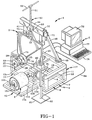
- FIG. 1 is a perspective view of the portable tire uniformity test machine of the invention including the various electronic processing and display apparatus;
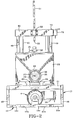
- FIG. 2 is a front elevational view of the test machine of FIG. 1 with the electronic processing and display apparatus removed therefrom;
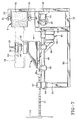
- FIG. 3 is a right side elevational view of the test machine shown in FIG. 2;
- FIG. 4 is a back elevational view of the test machine;
- FIG. 5 is a left side elevational view of the test machine, as shown in FIG. 2;
- FIG. 6 is a view similar to FIG. 5 showing the test machine in operating position with a tire/wheel assembly being shown in dot-dash lines; and
- FIG. 7 is a view similar to FIG. 6 but showing a different orientation of the tire test machine.
- Similar numerals refer to similar parts throughout the drawings.
- The improved portable tire uniformity test machine of the invention is indicated generally at 1, and is shown in assembled operating position in FIG. 1.
Machine 1 includes as its main components, a unique, compact, sturdy frame indicated generally at 2, a tire/wheel assembly mounting plate indicated generally at 3, aroad wheel 4, and electronic processing apparatus indicated generally at 5. - Frame 2 is formed by a plurality of longitudinally and transversely extending frame members, preferably formed of hollow rectangular cross-sectional steel members. In the preferred embodiment, frame 2 includes a
base 6 for supporting the machine on a generally flat planar surface.Base 6 includes four spaced parallel longitudinally extendingbase members front frame members Front frame member 12 is formed by three separateframe member sections - A base extension, indicated generally at 15, is formed by a pair of spaced parallel longitudinally extending
frame members rear frame members Rear frame member 15d is spaced from and parallel withtransverse frame member 12b. - A box-like subframe, indicated generally at 17, is mounted on
base 6 and includes fourcorner frame members 18 which are mounted on the ends oflongitudinal base members Subframe 17 further includes a pair of longitudinally extendingtop end members 19 and a pair of spaced transversely extendingparallel end members subframe 17. - Tire/wheel
assembly mounting plate 3 has a generally triangular configuration, with a planar back surface 23 (FIG. 4) and atriangular front surface 24 on which is rotatably mounted a tirerim backing plate 25.Plate 25 preferably is located at the apex of the triangular mounting plate. Abearing hub assembly 26, a centeringcone 29, and alocking hub 33 are mounted on a threadedspindle 27, which is mounted on and extends outwardly fromrim backing plate 25.Road wheel 4 is rotatably mounted beneathrim backing plate 25 on a pair of pillow blocks 30 (FIG. 3) which rotatably supportroad wheel shaft 31 therein in suitable bearings.Road wheel 4 preferably has a roughenedouter surface 32 to provide for frictional engagement when atire 58 is brought into pressing engagement therewith. In the preferred embodiment,road wheel 4 will have a diameter of approximately one foot which is considerably less than the heretofore road wheels used at fixed test sites having a diameter of several feet. -
Road wheel shaft 31 is connected through a gear box 34 (FIG. 4) to adrive motor 35 which extends in a cantilever fashion outwardly fromgear box 34.Gear box 34 in turn is mounted on a pair ofcross braces 36 which extend acrosstransverse cross members subframe 17, therefore decreasing the size and providing compactness for frame 2. - Tire/wheel
assembly mounting plate 3 is slidably mounted by upper and lower spaced pairs ofbearing blocks back surface 23 thereof, and are slidably engaged with a pair of vertically extendingspaced slide rods 41.Slide rods 41 are mounted on and extend upwardly frompedestals 42 which are bolted to the top frame members ofsubframe 17. The top ends ofslide rods 41 are secured adjacent the ends of ahorizontal cross member 44 to provide lateral stability to the slide rods. - A pair of angularly extending reinforcing
struts 46 are connected byattachment plates 47 to crossmember 44 at their upper end and by mountingpads 48 at their lower end toend frame member 20 ofsubframe 18. In order to increase the compactness of frame 2,struts 46 form an included angle withguide rods 41 of approximately 25°. - A manually operated loading mechanism indicated generally at 50, is mounted on
cross member 44 and is engageable with tire/wheelassembly mounting plate 3. In the preferred embodiment,loading mechanism 50 consists of a threadedrod 51 having ahandle 52.Rod 51 extends through a threadedblock 53 which is mounted oncross member 44.End 55 of threaded shaft 51 (FIG. 2) is rotatably advanced by manual rotation ofhandle 52 into engagement with aload cell 56 which will measure the amount of force applied to mountingplate 3 and, correspondingly, the force thattire 58 exerts onroad wheel 4. However, if desired,loading mechanism 50 can be replaced with a pneumatic, hydraulic, electrical or other type of mechanical loading device without departing from the concept of the invention. - A power-actuated lift mechanism, indicated generally at 60, is mounted between
wheel mounting plate 3 andsubframe 17 for ease of raising and loweringmounting plate 3 for the mounting and removal of a tire/wheel assembly thereon. In the preferred embodiment,lift mechanism 60 includes apneumatic air spring 61 which is connected by asupply tube 62 to a remote source of compressed air.Air spring 61 is operatively connected tomounting plate 3 by a strut assembly, indicated generally at 65 (FIG. 4). -
Strut assembly 65 includes a pair of spaced parallel angularly extendingstruts 66 which are attached at 67 toback surface 23 ofmounting plate 3, and at their lower end, to ahorizontal plate 68 which extends betweenspaced struts 66. An upper end cap or end member of theair spring 61 is connected to an inverted U-shapedplate 69 which is mounted on the bottom surface ofplate 68. The pneumatic control lines forair spring 61 preferably are connected to a manually operated ON/OFF control valve 72 mounted adjacent the end ofcross member 44 for ease of operation by the operating personnel when loading and unloadingtire 58 onto and off ofmounting plate 3. Other types of lift mechanisms can be used instead ofair spring 61, such as hydraulic or pneumatic cylinders, mechanical or electrical devices, etc. without departing from the invention. - If desired, a
second load cell 73 may be mounted on tirerim backing plate 25, and in the preferred embodiment, is of the type which will measure forces acting upon the tire in five axes, namely, up and down radial forces, lateral forward and back radial forces, and a twisting moment on the tire.Load cells power lines processing unit 5.Processing unit 5 may consist of ausual computer 77 having akeyboard 78 and amonitor 79 which will provide a graphic display of the tire uniformities. - A usual sensing probe 80 (FIG. 1) is mounted on the end of an
arm 81 which extends outwardly from anadjustable stand post 82 that extends upwardly from abase 83.Probe 80 also supplies test data and readout signals through aline 84 toprocessing unit 5, principally detecting the roundness of the tire. - In operation, a tire/wheel assembly 57, which includes
tire 58 and arim 59, is clamped on bearinghub assembly 26 by lockinghub 33.Valve 72 then is operated to relieve the pressure inair spring 61, permitting mountingplate 3 and the tire/wheel assembly to move downwardly onslide rods 41 untiltire 58 comes into contact withroad wheel 4, as shown in FIG. 6.Handle 52 then is rotated, applying a predetermined force onto mountingplate 3 and, correspondingly, betweentire 58 androad wheel 4. The amount of this applied force is detected byload cell 56 and supplied toprocessing unit 5 throughsignal line 75.Motor 35 then is rotated at a constantspeed revolving tire 58 by the frictional engagement with the roughened surface ofroad wheel 4. - A three-
position switch 71 is mounted oncross member 44 to operatemotor 35 androad wheel 4 in forward, reverse and OFF modes. Theradial runout probe 80 is located at the optimal distance from the center of the tire, and after the computer program is initiated, a once-per-revolution trigger from an encoder 88 (FIG. 4) usually associated withspindle 27, starts data collection. The signals from the load cells and probe are supplied toprocessor 5, which stores the data and, if desired, provides an instantaneous graphical readout onmonitor 79 and/or a subsequent hard copy printout thereof. - Various types of well known or easily developed software packages, similar to that being presently used with the larger fixed tire uniformity test machines, may be utilized for deriving the desired output readings.
- A modified form of
improved machine 1 and, in particular, of frame 2 is shown in FIG. 7. In this embodiment, a frame indicated generally at 90, which is similar in nearly all respects to frame 2, is mounted on a planar surface so thatspindle 27 extends perpendicularly upwardly therefrom for placement of a tire/wheel assembly in a vertical direction thereon. When used in such an orientated position, as shown in FIG. 7, a pair of spacedvertical frame members 91 and a corresponding pair of horizontally extendingframe member extensions 92 are added to frame 2 to increase the rigidity of the machine frame. - The orientation of FIG. 7 is desirable where relatively large tire/wheel assemblies are being tested, enabling the wheel assemblies to be picked up and transported and placed onto
spindle 27 by an overhead crane or other transport mechanism. - In accordance with the invention, both frames 2 and 90 provide a relatively compact and sturdy construction and arrangement of frame components, which enable the road wheel and motor to be mounted thereon together with the power-operated lift mechanism, such as
air spring 61, as well as providing the load cell mounting arrangements and the slide rails for the movement of tire/wheelassembly mounting plate 3 therealong, including the manually operated loading mechanism, namely, threadedshaft 51, or other type of loading mechanism. Thus,improved machine 1, using the particular frame constructions 2 and 90, enables the unit to be easily transported in a truck to a tire assembly plant or other remote locations heretofore unaccessible for testing of tire/wheel assemblies and/or of the tire or rim components thereof, eliminating the heretofore need of shipping the tire/wheel assembly or tire to a remote laboratory test site. The preferred embodiment has a total weight of between 500 and 600 lbs. and is easily moved by a forklift vehicle, which is readily available at most plant sites. - Accordingly, the improved portable tire uniformity test machine is simplified, provides an effective, safe, inexpensive, and efficient device which achieves all the enumerated objectives, provides for eliminating difficulties encountered with prior devices, and solves problems and obtains new results in the art.
- In the foregoing description, certain terms have been used for brevity, clearness and understanding; but no unnecessary limitations are to be implied therefrom beyond the requirement of the prior art, because such terms are used for descriptive purposes and are intended to be broadly construed.
- Moreover, the description and illustration of the invention is by way of example, and the scope of the invention is not limited to the exact details shown or described.
- Having now described the features, discoveries and principles of the invention, the manner in which the improved portable tire uniformity test machine is constructed and used, the characteristics of the construction, and the advantageous, new and useful results obtained; the new and useful structures, devices, elements, arrangements, parts and combinations, are set forth in the appended claims.
Claims (10)
- A portable machine for testing on site the uniformity of tire/wheel assemblies and/or components thereof including:
a frame having a base formed by a plurality of frame members lying in a common plane for supporting the machine on a substantially horizontal planar surface, a subframe mounted on the base and extending upwardly therefrom, and a slide subassembly mounted on the subframe and extending outwardly therefrom;
a tire/wheel assembly mounting plate slidably mounted on the slide subassembly;
means for moving the tire/wheel assembly mounting plate on the slide subassembly;
a road wheel rotatably mounted on the base;
a motor mounted on the base and drivingly engaged with the road wheel for rotating said road wheel; and
load means for moving the tire/wheel assembly mounting plate toward the road wheel to apply a measurable pressure between a tire of a tire/wheel assembly mounted on said mounting plate and the road wheel. - The machine defined in Claim 1 including first load detecting means for measuring the amount of pressure between a tire and the road wheel exerted by the load means.
- The machine defined in Claim 1 including probe means for generating a signal indicative of the magnitude and locations of the roundness of a tire; and electronic processing means for receiving and processing the signal from the probe means including display means for providing a graphical display of nonuniformities of a tire being tested.
- The machine defined in Claim 1 in which the slide subassembly includes a pair of spaced parallel slide rods extending between a cross member, and at least a pair of reinforcing struts extending in an acute angular relationship between the cross member and the box-like subframe; and in which the slide subassembly further includes bearing means for slidably mounting the tire/wheel assembly mounting plate on the slide rods.
- The machine defined in Claim 4 in which the load means is mounted on the cross member of the slide subassembly and engages the tire/wheel assembly mounting plate; and in which the load means includes a threaded shaft adapted to be manually advanced into engagement with the tire/wheel assembly mounting plate.
- The machine defined in Claim 4 in which the reinforcing struts form an included angle of approximately 25° with respect to the slide rods; in which the tire/wheel assembly mounting plate has a generally triangular configuration with a generally planar base and an apex; in which the bearing means is mounted on the base of said mounting plate; and in which a spindle extends outwardly from the apex and is adapted to support a tire/wheel assembly thereon.
- The machine defined in claim 4 in which the base includes a pair of spaced parallel longitudinally extending inner frame members on which the road wheel and motor are mounted, and another pair of spaced parallel longitudinally extending outer frame members extending parallel with and outboard of said inner frame members; in which the subframe has a box-like configuration and includes a corner support frame member extending outwardly from ends of the outer frame members, and a pair of transversely extending cross members; and in which the slide rods are mounted on one of the transverse cross members and the reinforcing struts are mounted on the other one of the said transverse cross members.
- The machine defined in Claim 1 in which the tire/wheel assembly mounting plate includes a spindle extending outwardly therefrom for supporting a tire/wheel assembly thereon; in which load detecting means is mounted on the spindle for measuring certain forces applied to a tire of a tire/wheel assembly by the load means and road wheel; and in which the load detecting means includes a load cell, said cell adapted to measure forces in five axes.
- The machine defined in Claim 1 in which certain of the frame members extend outwardly beyond the subframe and form an extension of the base; in which the road wheel is rotatably mounted by a pair of spaced bearings on said base extension; in which certain other of the frame members extend within the subframe; and in which the motor is mounted on said certain other frame members and is located within said subframe.
- The machine defined in Claim 1 including power lift means for moving the tire/wheel assembly mounting plate toward and away from the road wheel; in which the power lift means is an air spring; in which a strut assembly is mounted on the tire/wheel assembly mounting plate and extends over the subframe; and in which the air spring is located between the subframe and strut assembly.
Applications Claiming Priority (2)
| Application Number | Priority Date | Filing Date | Title |
|---|---|---|---|
| US08/206,991 US5448910A (en) | 1994-03-07 | 1994-03-07 | Portable tire uniformity test machine |
| US206991 | 1994-03-07 |
Publications (3)
| Publication Number | Publication Date |
|---|---|
| EP0671621A2 true EP0671621A2 (en) | 1995-09-13 |
| EP0671621A3 EP0671621A3 (en) | 1995-09-20 |
| EP0671621B1 EP0671621B1 (en) | 1998-04-15 |
Family
ID=22768770
Family Applications (1)
| Application Number | Title | Priority Date | Filing Date |
|---|---|---|---|
| EP95102647A Expired - Lifetime EP0671621B1 (en) | 1994-03-07 | 1995-02-24 | Portable tyre uniformity test machine |
Country Status (5)
| Country | Link |
|---|---|
| US (1) | US5448910A (en) |
| EP (1) | EP0671621B1 (en) |
| JP (1) | JPH07260638A (en) |
| DE (1) | DE69502042T2 (en) |
| ES (1) | ES2115280T3 (en) |
Cited By (5)
| Publication number | Priority date | Publication date | Assignee | Title |
|---|---|---|---|---|
| EP1033562A3 (en) * | 1999-03-03 | 2000-11-08 | Schenck RoTec GmbH | Procedure and device for reducing the vibrations provoked by a wheel-unit of a vehicle |
| DE10019565A1 (en) * | 2000-04-20 | 2001-10-25 | Zahnradfabrik Friedrichshafen | Tire uniformity checker, has separate force measurement |
| WO2011101006A1 (en) * | 2010-02-17 | 2011-08-25 | Snap-On Equipment Srl A Unico Socio | Tire changer and method of measuring force variations |
| US8250915B1 (en) | 2008-07-03 | 2012-08-28 | Hunter Engineering Company | Tire changer with actuated load roller |
| CN108871813A (en) * | 2018-06-27 | 2018-11-23 | 昆山睿力得软件技术有限公司 | A kind of high emulation tyre performance test experience platform |
Families Citing this family (20)
| Publication number | Priority date | Publication date | Assignee | Title |
|---|---|---|---|---|
| US6324908B1 (en) * | 1996-01-31 | 2001-12-04 | Hunter Engineering Company | Wheel balancer and control circuit therefor |
| US6336364B1 (en) | 1996-01-31 | 2002-01-08 | Hunter Engineering Company | Wheel balancer with wheel rim runout measurement |
| US6854329B2 (en) | 1996-01-31 | 2005-02-15 | Hunter Engineering Company | Wheel balancer with variation measurement |
| US6067848A (en) * | 1997-03-07 | 2000-05-30 | Bridgestone/Firestone, Inc. | Portable tire uniformity measurement system and method |
| US6050876A (en) * | 1997-08-08 | 2000-04-18 | Cabot Corporation | Automated abrader |
| US6089083A (en) * | 1997-08-22 | 2000-07-18 | Curtis; John Michael | Tire inspection and preparation device |
| US6178814B1 (en) | 1997-08-22 | 2001-01-30 | John Michael Curtis | Portable motorized tire support |
| GB9915052D0 (en) * | 1999-06-28 | 1999-08-25 | Lonsdale Anthony | Apparatus and method for detecting the condition of an item |
| US6834559B1 (en) * | 1999-07-09 | 2004-12-28 | Illinois Tool Works Inc. | Vibration compensation system for tire testing systems |
| US6763706B1 (en) * | 2003-02-12 | 2004-07-20 | Akron Special Machinery, Inc. | Load cell conicity calibration apparatus and method |
| US7591167B2 (en) * | 2006-11-20 | 2009-09-22 | Potts Gerald R | Methods and systems for measurement of tire rolling resistance |
| US8186215B2 (en) | 2008-06-09 | 2012-05-29 | Hunter Engineering Company | Method and system for determining non-uniformity characteristics of a vehicle tire and rim |
| JP5060506B2 (en) * | 2009-03-25 | 2012-10-31 | 株式会社神戸製鋼所 | Tire rolling resistance measuring device |
| KR101977406B1 (en) | 2010-03-10 | 2019-05-13 | 마이크로-포이즈 메져먼트 시스템스, 엘엘씨 | Tire testing apparatus having adjustable bead width |
| US8347702B2 (en) * | 2010-08-04 | 2013-01-08 | The Pullman Company | Tracked vehicle track backer pad and road wheel tire test machine and method |
| CN103842792B (en) * | 2011-10-06 | 2016-06-29 | 株式会社神户制钢所 | Tire uniformity test device and tire uniformity test method |
| CN105203333B (en) * | 2015-10-09 | 2017-07-28 | 浙江工业大学 | A kind of double transmission driving wheel test devices |
| JP6844148B2 (en) * | 2016-08-23 | 2021-03-17 | 横浜ゴム株式会社 | Abrasion tester |
| JP6735254B2 (en) * | 2017-06-21 | 2020-08-05 | 株式会社神戸製鋼所 | Device and method for calculating tire dynamic load radius |
| JP6777619B2 (en) * | 2017-11-07 | 2020-10-28 | 株式会社神戸製鋼所 | Tire tangential load measuring device and tire rolling resistance evaluation device |
Family Cites Families (11)
| Publication number | Priority date | Publication date | Assignee | Title |
|---|---|---|---|---|
| DE2023015A1 (en) * | 1970-05-12 | 1971-11-25 | Roell & Korthaus Kg | Testing device for automobile tires |
| US4655080A (en) * | 1985-10-02 | 1987-04-07 | Theodore Ongaro | Dynamic tire balancing machine and method |
| US4691564A (en) * | 1986-07-01 | 1987-09-08 | G. R. Potts Associates, Inc. | High speed tire uniformity testing device |
| US4821582A (en) * | 1987-12-02 | 1989-04-18 | Mts Systems Corporation | Load transducer |
| US4829815A (en) * | 1988-05-13 | 1989-05-16 | The Firestone Tire & Rubber Company | Tire testing apparatus |
| JP2823579B2 (en) * | 1989-02-15 | 1998-11-11 | 株式会社豊田中央研究所 | Tire uniformity measuring device |
| DE3922288C2 (en) * | 1989-07-06 | 1997-04-10 | Hofmann Gmbh & Co Kg Maschinen | Method and device for checking the uniformity of pneumatic tires, in particular vehicle tires |
| DE3928921A1 (en) * | 1989-08-31 | 1991-03-07 | Hofmann Gmbh & Co Kg Maschinen | METHOD AND DEVICE FOR TESTING THE UNIFORMITY OF TIRES |
| JPH03150143A (en) * | 1989-11-06 | 1991-06-26 | Kobe Steel Ltd | Rim mounting device for tire uniformity machine |
| US5111687A (en) * | 1990-11-26 | 1992-05-12 | Standards Testing Laboratories, Inc. | Roadwheel for tire testing apparatus |
| US5323646A (en) * | 1992-08-27 | 1994-06-28 | Akron Special Machinery, Inc. | Frictionless carriage for tire uniformity machine loadwheel carriage |
-
1994
- 1994-03-07 US US08/206,991 patent/US5448910A/en not_active Expired - Fee Related
-
1995
- 1995-02-24 EP EP95102647A patent/EP0671621B1/en not_active Expired - Lifetime
- 1995-02-24 ES ES95102647T patent/ES2115280T3/en not_active Expired - Lifetime
- 1995-02-24 DE DE69502042T patent/DE69502042T2/en not_active Expired - Fee Related
- 1995-03-03 JP JP7068853A patent/JPH07260638A/en active Pending
Cited By (12)
| Publication number | Priority date | Publication date | Assignee | Title |
|---|---|---|---|---|
| EP1033562A3 (en) * | 1999-03-03 | 2000-11-08 | Schenck RoTec GmbH | Procedure and device for reducing the vibrations provoked by a wheel-unit of a vehicle |
| US6360593B1 (en) | 1999-03-03 | 2002-03-26 | Schenck Rotec Gmbh | Method and apparatus for reducing vibrations transmitted to a vehicle from a wheel unit |
| DE10019565A1 (en) * | 2000-04-20 | 2001-10-25 | Zahnradfabrik Friedrichshafen | Tire uniformity checker, has separate force measurement |
| US6779391B2 (en) | 2000-04-20 | 2004-08-24 | Zf Friedrichshafen Ag | Device for measuring the uniformity of a vehicle tire |
| US8250915B1 (en) | 2008-07-03 | 2012-08-28 | Hunter Engineering Company | Tire changer with actuated load roller |
| US8904863B1 (en) | 2008-07-03 | 2014-12-09 | Hunter Engineering Company | Tire changer with actuated load roller |
| US9731566B1 (en) | 2008-07-03 | 2017-08-15 | Hunter Engineering Company | Tire changer with actuated load roller |
| WO2011101006A1 (en) * | 2010-02-17 | 2011-08-25 | Snap-On Equipment Srl A Unico Socio | Tire changer and method of measuring force variations |
| EP2361791A1 (en) | 2010-02-17 | 2011-08-31 | Snap-on Equipment Srl a unico socio | Tyre changer and a method of measuring force variations acting between a peripheral surface of a wheel/tyre assembly and a roller |
| US9114676B2 (en) | 2010-02-17 | 2015-08-25 | Snap-On Equipment Srl A Unico Socio | Tire changer and method of measuring force variations |
| US9834047B2 (en) | 2010-02-17 | 2017-12-05 | Snap-On Equipment Srl A Unico Socio | Tire changer and method of measuring force variations |
| CN108871813A (en) * | 2018-06-27 | 2018-11-23 | 昆山睿力得软件技术有限公司 | A kind of high emulation tyre performance test experience platform |
Also Published As
| Publication number | Publication date |
|---|---|
| JPH07260638A (en) | 1995-10-13 |
| DE69502042T2 (en) | 1998-08-06 |
| EP0671621B1 (en) | 1998-04-15 |
| US5448910A (en) | 1995-09-12 |
| EP0671621A3 (en) | 1995-09-20 |
| DE69502042D1 (en) | 1998-05-20 |
| ES2115280T3 (en) | 1998-06-16 |
Similar Documents
| Publication | Publication Date | Title |
|---|---|---|
| US5448910A (en) | Portable tire uniformity test machine | |
| RU2546913C2 (en) | Test and assembly bench | |
| JP2823579B2 (en) | Tire uniformity measuring device | |
| US4679447A (en) | Method and apparatus for positioning and testing railroad wheels | |
| CN103547897B (en) | For the balancing machine of balancing vehicle wheels | |
| JPS59109836A (en) | Dynamic wheel balance of small speed and its method | |
| US4584873A (en) | Integrated tire conditioning system and method | |
| EP0290601A1 (en) | Combination grinder/balancer. | |
| US4359896A (en) | Dynamic tire testing apparatus | |
| US4763523A (en) | Roller bearing testing device | |
| US3078720A (en) | Apparatus for balancing vehicle wheels | |
| JPH01116430A (en) | Load wheel centering apparatus | |
| WO2004044543A1 (en) | Wheel balancing system with integrated wheel lift, loaded mode testing, and wheel imaging system | |
| GB2104010A (en) | >Tyre testing apparatus | |
| EP0362346B1 (en) | Vehicle inspection trailer | |
| US3965731A (en) | Roller brake tester | |
| JPH0715423B2 (en) | Method and apparatus for determining wheel imbalance | |
| JPH0295233A (en) | Dynamic balancing testing machine for wheel | |
| EP0011491A1 (en) | Method and apparatus for measuring vehicle track alignment | |
| JP3333598B2 (en) | Chassis dynamometer verification device | |
| JP3216958B2 (en) | Method and apparatus for measuring side force of tire running tester | |
| JPH0545547U (en) | Tire flat spot generator | |
| CN119104324B (en) | Multi-parameter detection device and method for wheel disc brake assembly | |
| CN223228958U (en) | A building structure crack width detection device | |
| CN216050409U (en) | Automobile wheel end dragging torque measuring device |
Legal Events
| Date | Code | Title | Description |
|---|---|---|---|
| PUAI | Public reference made under article 153(3) epc to a published international application that has entered the european phase |
Free format text: ORIGINAL CODE: 0009012 |
|
| PUAL | Search report despatched |
Free format text: ORIGINAL CODE: 0009013 |
|
| AK | Designated contracting states |
Kind code of ref document: A2 Designated state(s): DE ES FR GB IT |
|
| AK | Designated contracting states |
Kind code of ref document: A3 Designated state(s): DE ES FR GB IT |
|
| 17P | Request for examination filed |
Effective date: 19950912 |
|
| 17Q | First examination report despatched |
Effective date: 19970414 |
|
| GRAG | Despatch of communication of intention to grant |
Free format text: ORIGINAL CODE: EPIDOS AGRA |
|
| GRAG | Despatch of communication of intention to grant |
Free format text: ORIGINAL CODE: EPIDOS AGRA |
|
| GRAH | Despatch of communication of intention to grant a patent |
Free format text: ORIGINAL CODE: EPIDOS IGRA |
|
| GRAH | Despatch of communication of intention to grant a patent |
Free format text: ORIGINAL CODE: EPIDOS IGRA |
|
| GRAA | (expected) grant |
Free format text: ORIGINAL CODE: 0009210 |
|
| AK | Designated contracting states |
Kind code of ref document: B1 Designated state(s): DE ES FR GB IT |
|
| REF | Corresponds to: |
Ref document number: 69502042 Country of ref document: DE Date of ref document: 19980520 |
|
| REG | Reference to a national code |
Ref country code: ES Ref legal event code: FG2A Ref document number: 2115280 Country of ref document: ES Kind code of ref document: T3 |
|
| ET | Fr: translation filed | ||
| ITF | It: translation for a ep patent filed | ||
| PLBE | No opposition filed within time limit |
Free format text: ORIGINAL CODE: 0009261 |
|
| STAA | Information on the status of an ep patent application or granted ep patent |
Free format text: STATUS: NO OPPOSITION FILED WITHIN TIME LIMIT |
|
| 26N | No opposition filed | ||
| REG | Reference to a national code |
Ref country code: GB Ref legal event code: IF02 |
|
| PGFP | Annual fee paid to national office [announced via postgrant information from national office to epo] |
Ref country code: GB Payment date: 20060109 Year of fee payment: 12 |
|
| PGFP | Annual fee paid to national office [announced via postgrant information from national office to epo] |
Ref country code: FR Payment date: 20060202 Year of fee payment: 12 |
|
| PGFP | Annual fee paid to national office [announced via postgrant information from national office to epo] |
Ref country code: ES Payment date: 20060214 Year of fee payment: 12 |
|
| PGFP | Annual fee paid to national office [announced via postgrant information from national office to epo] |
Ref country code: IT Payment date: 20060228 Year of fee payment: 12 Ref country code: DE Payment date: 20060228 Year of fee payment: 12 |
|
| GBPC | Gb: european patent ceased through non-payment of renewal fee |
Effective date: 20070224 |
|
| REG | Reference to a national code |
Ref country code: FR Ref legal event code: ST Effective date: 20071030 |
|
| PG25 | Lapsed in a contracting state [announced via postgrant information from national office to epo] |
Ref country code: DE Free format text: LAPSE BECAUSE OF NON-PAYMENT OF DUE FEES Effective date: 20070901 |
|
| PG25 | Lapsed in a contracting state [announced via postgrant information from national office to epo] |
Ref country code: GB Free format text: LAPSE BECAUSE OF NON-PAYMENT OF DUE FEES Effective date: 20070224 Ref country code: FR Free format text: LAPSE BECAUSE OF NON-PAYMENT OF DUE FEES Effective date: 20070228 |
|
| REG | Reference to a national code |
Ref country code: ES Ref legal event code: FD2A Effective date: 20070226 |
|
| PG25 | Lapsed in a contracting state [announced via postgrant information from national office to epo] |
Ref country code: ES Free format text: LAPSE BECAUSE OF NON-PAYMENT OF DUE FEES Effective date: 20070226 |
|
| PG25 | Lapsed in a contracting state [announced via postgrant information from national office to epo] |
Ref country code: IT Free format text: LAPSE BECAUSE OF NON-PAYMENT OF DUE FEES Effective date: 20070224 |