EP0671197A1 - Settler for liquid to be purified - Google Patents
Settler for liquid to be purified Download PDFInfo
- Publication number
- EP0671197A1 EP0671197A1 EP94830350A EP94830350A EP0671197A1 EP 0671197 A1 EP0671197 A1 EP 0671197A1 EP 94830350 A EP94830350 A EP 94830350A EP 94830350 A EP94830350 A EP 94830350A EP 0671197 A1 EP0671197 A1 EP 0671197A1
- Authority
- EP
- European Patent Office
- Prior art keywords
- tank
- truncated
- settler
- liquid
- purified
- Prior art date
- Legal status (The legal status is an assumption and is not a legal conclusion. Google has not performed a legal analysis and makes no representation as to the accuracy of the status listed.)
- Withdrawn
Links
- 239000007788 liquid Substances 0.000 title claims abstract description 24
- 238000005192 partition Methods 0.000 claims abstract description 5
- 239000013049 sediment Substances 0.000 claims description 7
- 125000006850 spacer group Chemical group 0.000 claims description 2
- 230000005484 gravity Effects 0.000 description 4
- XLYOFNOQVPJJNP-UHFFFAOYSA-N water Substances O XLYOFNOQVPJJNP-UHFFFAOYSA-N 0.000 description 4
- 239000002245 particle Substances 0.000 description 3
- 239000011152 fibreglass Substances 0.000 description 2
- 239000012530 fluid Substances 0.000 description 2
- 239000002244 precipitate Substances 0.000 description 2
- 239000008213 purified water Substances 0.000 description 2
- 238000010908 decantation Methods 0.000 description 1
- 238000001914 filtration Methods 0.000 description 1
- 239000012535 impurity Substances 0.000 description 1
- 230000004048 modification Effects 0.000 description 1
- 238000012986 modification Methods 0.000 description 1
- 238000000746 purification Methods 0.000 description 1
- 230000000630 rising effect Effects 0.000 description 1
- 238000000926 separation method Methods 0.000 description 1
- 239000000126 substance Substances 0.000 description 1
- 210000002105 tongue Anatomy 0.000 description 1
Images
Classifications
-
- B—PERFORMING OPERATIONS; TRANSPORTING
- B01—PHYSICAL OR CHEMICAL PROCESSES OR APPARATUS IN GENERAL
- B01D—SEPARATION
- B01D21/00—Separation of suspended solid particles from liquids by sedimentation
- B01D21/24—Feed or discharge mechanisms for settling tanks
- B01D21/2405—Feed mechanisms for settling tanks
- B01D21/2411—Feed mechanisms for settling tanks having a tangential inlet
-
- B—PERFORMING OPERATIONS; TRANSPORTING
- B01—PHYSICAL OR CHEMICAL PROCESSES OR APPARATUS IN GENERAL
- B01D—SEPARATION
- B01D21/00—Separation of suspended solid particles from liquids by sedimentation
- B01D21/003—Sedimentation tanks provided with a plurality of compartments separated by a partition wall
- B01D21/0036—Horizontal partition walls
-
- B—PERFORMING OPERATIONS; TRANSPORTING
- B01—PHYSICAL OR CHEMICAL PROCESSES OR APPARATUS IN GENERAL
- B01D—SEPARATION
- B01D21/00—Separation of suspended solid particles from liquids by sedimentation
- B01D21/0039—Settling tanks provided with contact surfaces, e.g. baffles, particles
- B01D21/0045—Plurality of essentially parallel plates
-
- B—PERFORMING OPERATIONS; TRANSPORTING
- B01—PHYSICAL OR CHEMICAL PROCESSES OR APPARATUS IN GENERAL
- B01D—SEPARATION
- B01D21/00—Separation of suspended solid particles from liquids by sedimentation
- B01D21/0039—Settling tanks provided with contact surfaces, e.g. baffles, particles
- B01D21/0057—Settling tanks provided with contact surfaces, e.g. baffles, particles with counter-current flow direction of liquid and solid particles
-
- B—PERFORMING OPERATIONS; TRANSPORTING
- B01—PHYSICAL OR CHEMICAL PROCESSES OR APPARATUS IN GENERAL
- B01D—SEPARATION
- B01D21/00—Separation of suspended solid particles from liquids by sedimentation
- B01D21/02—Settling tanks with single outlets for the separated liquid
-
- B—PERFORMING OPERATIONS; TRANSPORTING
- B01—PHYSICAL OR CHEMICAL PROCESSES OR APPARATUS IN GENERAL
- B01D—SEPARATION
- B01D21/00—Separation of suspended solid particles from liquids by sedimentation
- B01D21/24—Feed or discharge mechanisms for settling tanks
- B01D21/2427—The feed or discharge opening located at a distant position from the side walls
Definitions
- the present invention concerns gravity settlers-decanters for liquids to be purified, usually water containing sediment and heavier substances.
- the known settlers comprise a vertical tank provided with a conical bottom, i.e. hopper shaped, and inside planes projecting from the walls towards the centre.
- the liquid to be purified delivered into the tank, with the help of the planes which prevent sediment from emerging, progressively releases the heaviest particles, which deposit onto the conical bottom for being evacuated, whereas the purified fluid rises to the surface and is collected from the top of the tank.
- the aim of the present invention is to obviate said disadvantageous characteristics by providing a settler of enhanced efficiency and therefore suitable for permitting purification of liquid in greater quantities, though having the same dimensions as known settlers.
- a settler according to the present invention will produce the same quantity of purified liquid as any know settlers, though with a much smaller tank and therefore smaller dimensions and lower price.
- Another object of the invention is to provide a settler for liquids to be purified in which sediment settling may be achieved in two ways: by gravity and through a multiplicity of inclined planes, which intercept the liquid rising and allow better and quicker treatment of liquid.
- a further and not lesser object of the invention is to provide a settling system for fluids to be purified which is suitable for being applied both to new and, advantageously, traditional existing settlers in order to enhance their efficiency, with the possibility of expanding filtering surfaces according to requirements.
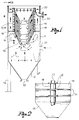
- the settler according to the invention comprises a vertical-axis cylindrical tank 11 having a conical bottom 12, i.e. hopper shaped, with an outlet 13 for sediment.
- the tank 11 is made, for example, in fibreglass and is fixed on supporting legs 14.
- Said truncated-cone shaped elements 15 are stacked coaxially with their minimum diameters facing the tank bottom, but are spaced parallelly and vertically so as to define intermediate passages 16 which extend conically from the element centre holes outwards.
- the truncated-cone elements 15 may be provided with side tongues 15' connected through connecting rods 17 with spacers 18 interposed, which make for easier assembly in stacked and spaced position.
- a horizontal partition 19 located proximate to and around the lower truncated-cone shaped element divides the tank into a lower chamber A and an upper chamber B and helps keep the element assembly 15 properly centred in the tank.
- a collecting channel 20 for purified water may be provided around the upper truncated-cone element, proximate to the top thereof.
- An inlet duct 21 for the delivery of liquid to be purified is connected to the lower part of the tank 11, i.e. below the horizontal partition 19; an outlet duct 22 for purified water is connected to the top channel 20.
- the liquid to be treated flows into the lower chamber A of the tank and progressively rises by passing through the conical passages 16 provided in the upper part B of the tank according to arrows F drawn in section line in Figure 1.
- the lower chamber A of the tank 11 functions as a gravity decanter for the separation of the heaviest particles transported by the liquid.
- the lightest particles of impurities are forced through the passages 16, i.e. along the inclined planes defined by the truncated-cone shaped elements 15, where they agglomerate and - once grown in size - precipitate to the bottom, where they finally deposit.
- Arrows G in Figure 1 indicates the sediment which precipitates to the tank bottom.
- Purified liquid rises into the upper chamber B and to the surface according to arrows H in bold lines, and may be collected through the outlet duct 22.
- the truncated-cone shaped elements may be assembled in any other adequate way, and a duct arranged axially, from above, with respect to the tank and extending coaxially through the truncated-cone shaped elements to the lower part of the tank may be provided for the delivery of liquid to be treated instead of a side duct 21.
Landscapes
- Chemical & Material Sciences (AREA)
- Chemical Kinetics & Catalysis (AREA)
- Extraction Or Liquid Replacement (AREA)
Abstract
Description
- The present invention concerns gravity settlers-decanters for liquids to be purified, usually water containing sediment and heavier substances.
- In general, the known settlers comprise a vertical tank provided with a conical bottom, i.e. hopper shaped, and inside planes projecting from the walls towards the centre. The liquid to be purified delivered into the tank, with the help of the planes which prevent sediment from emerging, progressively releases the heaviest particles, which deposit onto the conical bottom for being evacuated, whereas the purified fluid rises to the surface and is collected from the top of the tank.
- In these known settlers, sediment substantially deposits only by gravity decantation. Their efficiency is rather low and, for treating considerable quantities of liquid, tanks of great capacity must be installed, which are disadvantageously bulky and expensive.
- The aim of the present invention is to obviate said disadvantageous characteristics by providing a settler of enhanced efficiency and therefore suitable for permitting purification of liquid in greater quantities, though having the same dimensions as known settlers. In other words, a settler according to the present invention will produce the same quantity of purified liquid as any know settlers, though with a much smaller tank and therefore smaller dimensions and lower price.
- Another object of the invention is to provide a settler for liquids to be purified in which sediment settling may be achieved in two ways: by gravity and through a multiplicity of inclined planes, which intercept the liquid rising and allow better and quicker treatment of liquid.
- A further and not lesser object of the invention is to provide a settling system for fluids to be purified which is suitable for being applied both to new and, advantageously, traditional existing settlers in order to enhance their efficiency, with the possibility of expanding filtering surfaces according to requirements.
- The settler according to the present invention is as claimed in claim 1. Further details will become apparent from the continuation of the description, with reference to the accompanying drawings, in which:
- Figure 1 shows a vertical sectional view of the settler according to the invention; and
- Figure 2 shows a partial sectional view of a detail according to arrows II-II in Figure 1.
- The settler according to the invention comprises a vertical-axis
cylindrical tank 11 having aconical bottom 12, i.e. hopper shaped, with anoutlet 13 for sediment. Thetank 11 is made, for example, in fibreglass and is fixed on supportinglegs 14. - A plurality of hollow truncated-cone shaped
elements 15 in fibreglass as well, whose maximum diameter is smaller than the tank diameter, are provided in thetank 11, in proximity to upper part thereof. Said truncated-coneshaped elements 15 are stacked coaxially with their minimum diameters facing the tank bottom, but are spaced parallelly and vertically so as to defineintermediate passages 16 which extend conically from the element centre holes outwards. - The truncated-
cone elements 15 may be provided with side tongues 15' connected through connectingrods 17 withspacers 18 interposed, which make for easier assembly in stacked and spaced position. - A
horizontal partition 19 located proximate to and around the lower truncated-cone shaped element divides the tank into a lower chamber A and an upper chamber B and helps keep theelement assembly 15 properly centred in the tank. Acollecting channel 20 for purified water may be provided around the upper truncated-cone element, proximate to the top thereof. Aninlet duct 21 for the delivery of liquid to be purified is connected to the lower part of thetank 11, i.e. below thehorizontal partition 19; anoutlet duct 22 for purified water is connected to thetop channel 20. - The liquid to be treated, in general water, flows into the lower chamber A of the tank and progressively rises by passing through the
conical passages 16 provided in the upper part B of the tank according to arrows F drawn in section line in Figure 1. - The lower chamber A of the
tank 11 functions as a gravity decanter for the separation of the heaviest particles transported by the liquid. The lightest particles of impurities are forced through thepassages 16, i.e. along the inclined planes defined by the truncated-cone shapedelements 15, where they agglomerate and - once grown in size - precipitate to the bottom, where they finally deposit. Arrows G in Figure 1 indicates the sediment which precipitates to the tank bottom. - Purified liquid rises into the upper chamber B and to the surface according to arrows H in bold lines, and may be collected through the
outlet duct 22. - The objects mentioned are achieved by the above described settler, which, in its details, is susceptible to modifications and variations all of which are within the scope of the inventive concept. Thus, as an example, the truncated-cone shaped elements may be assembled in any other adequate way, and a duct arranged axially, from above, with respect to the tank and extending coaxially through the truncated-cone shaped elements to the lower part of the tank may be provided for the delivery of liquid to be treated instead of a
side duct 21.
Claims (4)
- A settler for liquids to be purified comprising a vertical-axis tank (11) having a conical bottom (12) with a bottom outlet (13) for sediment, provided with an inlet duct (21) for the delivery of liquid to be treated and an outlet duct (22) for purified liquid, characterized in that said tank (11) includes a plurality of hollow, truncated-cone shaped elements (15) whose maximum diameter is smaller than the tank diameter, stacked coaxially with the minimum diameter facing the tank bottom and spaced parallelly and vertically so as to define intermediate passages (16) which extend conically from the element centre holes outwards, and in that, proximate to the lower truncated-cone shaped element, an intermediate horizontal partition (19) is provided which divides the tank into a lower chamber (A) and an upper chamber (B), the inlet duct (21) for the delivery of dirty liquid opening in proximity to said lower chamber (A) while the outlet duct (22) for purified liquid is connected to the upper chamber (B) of the tank.
- A settler as claimed in claim 1, wherein said truncated-cone shaped elements (15) are connected to one another and kept spaced by means of side connecting rods (17) and spacers (18), and wherein the whole assembly of truncated-cone elements is centred in the tank by said intermediate partition (19) and by a channel-shaped element (20) located at the top of said elements, the outlet duct (22) for purified liquid being connected to said channel-shaped element.
- A settler as claimed in claims 1 and 2, wherein all the passages (16) defined by the truncated-cone shaped elements (15) open on the upper chamber (B) of the tank.
- A settler as claimed in the previous claims, wherein the inlet duct (21) for the delivery of dirty liquid is connected to the tank laterally or extends from above coaxially with respect to the truncated-cone shaped elements to the lower chamber (A) of the tank.
Applications Claiming Priority (2)
| Application Number | Priority Date | Filing Date | Title |
|---|---|---|---|
| IT94BS000015A ITBS940015A1 (en) | 1994-03-08 | 1994-03-08 | SEDIMENTER FOR LIQUIDS TO BE CLARIFIED |
| ITBS940015 | 1994-03-08 |
Publications (1)
| Publication Number | Publication Date |
|---|---|
| EP0671197A1 true EP0671197A1 (en) | 1995-09-13 |
Family
ID=11345233
Family Applications (1)
| Application Number | Title | Priority Date | Filing Date |
|---|---|---|---|
| EP94830350A Withdrawn EP0671197A1 (en) | 1994-03-08 | 1994-07-11 | Settler for liquid to be purified |
Country Status (2)
| Country | Link |
|---|---|
| EP (1) | EP0671197A1 (en) |
| IT (1) | ITBS940015A1 (en) |
Cited By (3)
| Publication number | Priority date | Publication date | Assignee | Title |
|---|---|---|---|---|
| GB2565859A (en) * | 2017-08-22 | 2019-02-27 | Hydro Int Plc | A tray unit for a wastewater treatment device and a method of assembling a tray assembly for a wastewater treatment device |
| WO2021236240A1 (en) | 2020-05-21 | 2021-11-25 | Smith & Loveless Inc. | Circular parallel plate grit remover |
| WO2024246567A1 (en) * | 2023-05-26 | 2024-12-05 | Organica Technológiák Zártkörűen Működő Részvénytársaság | Clarifier with concentric stacked cones |
Citations (3)
| Publication number | Priority date | Publication date | Assignee | Title |
|---|---|---|---|---|
| DE117538C (en) * | ||||
| DE2046470A1 (en) * | 1969-11-05 | 1971-05-13 | Alfa Laval AB, Tumba (Schweden) | Device for the continuous separation of a sludge-containing Gemi cal of two liquids |
| CH563180A5 (en) * | 1973-09-13 | 1975-06-30 | Escher Wyss Ag |
-
1994
- 1994-03-08 IT IT94BS000015A patent/ITBS940015A1/en active IP Right Grant
- 1994-07-11 EP EP94830350A patent/EP0671197A1/en not_active Withdrawn
Patent Citations (3)
| Publication number | Priority date | Publication date | Assignee | Title |
|---|---|---|---|---|
| DE117538C (en) * | ||||
| DE2046470A1 (en) * | 1969-11-05 | 1971-05-13 | Alfa Laval AB, Tumba (Schweden) | Device for the continuous separation of a sludge-containing Gemi cal of two liquids |
| CH563180A5 (en) * | 1973-09-13 | 1975-06-30 | Escher Wyss Ag |
Cited By (7)
| Publication number | Priority date | Publication date | Assignee | Title |
|---|---|---|---|---|
| GB2565859A (en) * | 2017-08-22 | 2019-02-27 | Hydro Int Plc | A tray unit for a wastewater treatment device and a method of assembling a tray assembly for a wastewater treatment device |
| US11027226B2 (en) * | 2017-08-22 | 2021-06-08 | Hydro International Ltd | Tray unit for a wastewater treatment device and a method of assembling a tray assembly for a wastewater treatment device |
| GB2565859B (en) * | 2017-08-22 | 2022-05-18 | Hydro Int Ltd | A tray unit for a wastewater treatment device and a method of assembling a tray assembly for a wastewater treatment device |
| WO2021236240A1 (en) | 2020-05-21 | 2021-11-25 | Smith & Loveless Inc. | Circular parallel plate grit remover |
| US11371234B2 (en) * | 2020-05-21 | 2022-06-28 | Smith & Loveless Inc. | Circular parallel plate grit remover |
| EP4081486A4 (en) * | 2020-05-21 | 2022-12-14 | Smith & Loveless Inc. | CIRCULAR DESANDER WITH PARALLEL PLATES |
| WO2024246567A1 (en) * | 2023-05-26 | 2024-12-05 | Organica Technológiák Zártkörűen Működő Részvénytársaság | Clarifier with concentric stacked cones |
Also Published As
| Publication number | Publication date |
|---|---|
| ITBS940015A0 (en) | 1994-03-08 |
| ITBS940015A1 (en) | 1995-09-08 |
Similar Documents
| Publication | Publication Date | Title |
|---|---|---|
| US3613889A (en) | Floating settler for separation of liquid and solid phases | |
| US3151961A (en) | Vortex-type de-aerator and strainer | |
| US4136012A (en) | Compact apparatus for the purification of waste water by a physical chemical treatment | |
| US4014791A (en) | Oil separator | |
| US3794171A (en) | Apparatus for purifying waste liquids | |
| US4447322A (en) | Apparatus for the cyclone separation of liquids having different densities | |
| US2793186A (en) | Apparatus for classifying or settling fluid suspensions | |
| US20120168389A1 (en) | Device for Turbulence Reduction | |
| US20030154860A1 (en) | Separators for three-phase or two-phase fluid mixtures realized with a centrifugal device designed for the separation of the gas from the liquid mixture | |
| AU615728B2 (en) | Settling vessel for an activated-sludge/sewage suspension | |
| US4341630A (en) | Arrangement for separation of a suspension or emulsion from liquids by flotation | |
| HU215329B (en) | Cyclone with double acting extraction system, and method for a biological water-treating | |
| US4988441A (en) | Clarification apparatus | |
| CA2053326A1 (en) | Apparatus for separating commingling heavier and lighter immiscible liquids | |
| US4446030A (en) | Liquid circulation and pressure tanks | |
| US4176068A (en) | Method for the separation from each other of the components of a mixture of water, oil and dirt (sludge) as well as apparatus for performing said method | |
| US3951818A (en) | Chevron clarifier | |
| JP2599538B2 (en) | Inclined plate type sedimentation tank and method for preventing clogging thereof | |
| EP0258359A1 (en) | Method of separating a medium in different components by means of gravity. | |
| US1733324A (en) | Process and apparatus for defecating liquid | |
| EP0069119B1 (en) | Fluid recovery system | |
| US5593589A (en) | Clarifier | |
| US3163685A (en) | Packed column with side stream withdrawal | |
| RU2191618C2 (en) | Method of separation of unstable dispersed systems and device for realization of this method | |
| US4490255A (en) | Combined settling and liquid storage tank |
Legal Events
| Date | Code | Title | Description |
|---|---|---|---|
| PUAI | Public reference made under article 153(3) epc to a published international application that has entered the european phase |
Free format text: ORIGINAL CODE: 0009012 |
|
| AK | Designated contracting states |
Kind code of ref document: A1 Designated state(s): AT BE CH DE DK ES FR GB GR IE IT LI LU MC NL PT SE |
|
| RAX | Requested extension states of the european patent have changed |
Free format text: SI |
|
| 17P | Request for examination filed |
Effective date: 19960203 |
|
| 17Q | First examination report despatched |
Effective date: 19960829 |
|
| GRAG | Despatch of communication of intention to grant |
Free format text: ORIGINAL CODE: EPIDOS AGRA |
|
| GRAH | Despatch of communication of intention to grant a patent |
Free format text: ORIGINAL CODE: EPIDOS IGRA |
|
| STAA | Information on the status of an ep patent application or granted ep patent |
Free format text: STATUS: THE APPLICATION IS DEEMED TO BE WITHDRAWN |
|
| 18D | Application deemed to be withdrawn |
Effective date: 19970729 |