EP0671146B1 - Simple blood sampling device - Google Patents
Simple blood sampling device Download PDFInfo
- Publication number
- EP0671146B1 EP0671146B1 EP94923097A EP94923097A EP0671146B1 EP 0671146 B1 EP0671146 B1 EP 0671146B1 EP 94923097 A EP94923097 A EP 94923097A EP 94923097 A EP94923097 A EP 94923097A EP 0671146 B1 EP0671146 B1 EP 0671146B1
- Authority
- EP
- European Patent Office
- Prior art keywords
- paracentetic
- suction
- skin
- decompression chamber
- decompression
- Prior art date
- Legal status (The legal status is an assumption and is not a legal conclusion. Google has not performed a legal analysis and makes no representation as to the accuracy of the status listed.)
- Expired - Lifetime
Links
Images

Classifications
-
- A—HUMAN NECESSITIES
- A61—MEDICAL OR VETERINARY SCIENCE; HYGIENE
- A61B—DIAGNOSIS; SURGERY; IDENTIFICATION
- A61B5/00—Measuring for diagnostic purposes; Identification of persons
- A61B5/15—Devices for taking samples of blood
- A61B5/151—Devices specially adapted for taking samples of capillary blood, e.g. by lancets, needles or blades
- A61B5/15142—Devices intended for single use, i.e. disposable
- A61B5/15144—Devices intended for single use, i.e. disposable comprising driving means, e.g. a spring, for retracting the piercing unit into the housing
-
- A—HUMAN NECESSITIES
- A61—MEDICAL OR VETERINARY SCIENCE; HYGIENE
- A61B—DIAGNOSIS; SURGERY; IDENTIFICATION
- A61B5/00—Measuring for diagnostic purposes; Identification of persons
- A61B5/15—Devices for taking samples of blood
- A61B5/150007—Details
- A61B5/150015—Source of blood
- A61B5/150022—Source of blood for capillary blood or interstitial fluid
-
- A—HUMAN NECESSITIES
- A61—MEDICAL OR VETERINARY SCIENCE; HYGIENE
- A61B—DIAGNOSIS; SURGERY; IDENTIFICATION
- A61B5/00—Measuring for diagnostic purposes; Identification of persons
- A61B5/15—Devices for taking samples of blood
- A61B5/150007—Details
- A61B5/150053—Details for enhanced collection of blood or interstitial fluid at the sample site, e.g. by applying compression, heat, vibration, ultrasound, suction or vacuum to tissue; for reduction of pain or discomfort; Skin piercing elements, e.g. blades, needles, lancets or canulas, with adjustable piercing speed
- A61B5/150061—Means for enhancing collection
- A61B5/150099—Means for enhancing collection by negative pressure, other than vacuum extraction into a syringe by pulling on the piston rod or into pre-evacuated tubes
-
- A—HUMAN NECESSITIES
- A61—MEDICAL OR VETERINARY SCIENCE; HYGIENE
- A61B—DIAGNOSIS; SURGERY; IDENTIFICATION
- A61B5/00—Measuring for diagnostic purposes; Identification of persons
- A61B5/15—Devices for taking samples of blood
- A61B5/151—Devices specially adapted for taking samples of capillary blood, e.g. by lancets, needles or blades
- A61B5/15101—Details
- A61B5/15103—Piercing procedure
- A61B5/15107—Piercing being assisted by a triggering mechanism
- A61B5/15111—Semi-automatically triggered, e.g. at the end of the cocking procedure, for instance by biasing the main drive spring or when reaching sufficient contact pressure, the piercing device is automatically triggered without any deliberate action by the user
-
- A—HUMAN NECESSITIES
- A61—MEDICAL OR VETERINARY SCIENCE; HYGIENE
- A61B—DIAGNOSIS; SURGERY; IDENTIFICATION
- A61B5/00—Measuring for diagnostic purposes; Identification of persons
- A61B5/15—Devices for taking samples of blood
- A61B5/150007—Details
- A61B5/150374—Details of piercing elements or protective means for preventing accidental injuries by such piercing elements
- A61B5/150381—Design of piercing elements
- A61B5/150442—Blade-like piercing elements, e.g. blades, cutters, knives, for cutting the skin
-
- A—HUMAN NECESSITIES
- A61—MEDICAL OR VETERINARY SCIENCE; HYGIENE
- A61B—DIAGNOSIS; SURGERY; IDENTIFICATION
- A61B5/00—Measuring for diagnostic purposes; Identification of persons
- A61B5/15—Devices for taking samples of blood
- A61B5/150007—Details
- A61B5/150748—Having means for aiding positioning of the piercing device at a location where the body is to be pierced
-
- A—HUMAN NECESSITIES
- A61—MEDICAL OR VETERINARY SCIENCE; HYGIENE
- A61B—DIAGNOSIS; SURGERY; IDENTIFICATION
- A61B5/00—Measuring for diagnostic purposes; Identification of persons
- A61B5/15—Devices for taking samples of blood
- A61B5/150969—Low-profile devices which resemble patches or plasters, e.g. also allowing collection of blood samples for testing
Definitions
- the present invention relates to a simple blood-collecting device. Specifically, it relates to a simple blood-collecting device which allows one to collect one's own blood.
- a blood sampling device comprising a vacuum chamber, a skin suction portion and a fixed piercing and cutting means.
- the vacuum chamber is applied to a local portion of a surface of skin of a subject to expand and rise up the skin by a vacuum suction action, in cooperation with the skin suction portion.
- the raised portion of the skin then comes in contact with and is pierced by the piercing and cutting means.
- the blood flowing out of the skin is collected in the vacuum chamber. After the blood is collected, the device is taken off the subject's skin surface.
- EP-A-0 103 664 discloses a device for the subcutaneous injection of medicine. It comprises a funnel with a fixed cannula which extends into a circular suction bell. This bell adjoins a vacuum chamber and communicates with it when a sliding sleeve is shifted by the application of the device to the skin. This sucks the skin up and pierces it by contact with the cannula tip. The skin withdraws from the cannula tip after return to atmospheric pressure of the bell.
- WO 92/11879 Another device for transdermal perfusion of fluids is disclosed in WO 92/11879. It comprises a housing attached to the skin adhesively and defines a chamber within which suction is applied to a treatment site. After formation of a suction blister, the blister is disrupted to expose a dermis layer of skin from which the epithelium has been removed. Liquid drug is then introduced into the chamber for transdermal perfusion directly through the dermis. Suction is applied to the chamber by means of an evacuated cell separated from the chamber by a disruptable membrane. A tubular member is activated to rupture the membrane, disrupt the blister and deliver liquid to the chamber in successive stages of operation of the device.
- the present invention is aimed at providing a device which allows blood to be collected in a painless, reliable manner.
- the present invention proposes a blood collecting device as defined in claim 1.
- Preferred features are defined in claim 2 to 9.
- This blood collecting device notably comprises a decompression chamber, a skin suction portion, paracentetic means and paracentesis-terminating (withdrawal) means.
- this blood-collecting device has a very simple construction, is compact and lightweight and uses no special parts, it is economical and may be used in a disposable manner.
- Figs. 1(a) to 1(d) are cross-sectional sketches of an embodiment of the device according to the present invention in its states of operation.
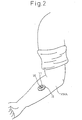
- Fig. 2 is a drawing showing the device of Fig. 1 in a state of use.
- the characteristics of the present invention are as follows. Decompression suction is concentrated on a local surface of the skin. As this local decompression suction is induced, the inner surface of the skin becomes congested with blood, causing enlargement and swelling of the epidermis. This swollen skin comes into contact with the paracentetic means preset at a prescribed position. Because the swollen skin is in a sufficiently enlarged state, the paracentetic means easily penetrates the skin (epidermis, etc.). After a certain period of time, a terminating procedure is performed to withdraw the paracentetic means, and decompression suction is again initiated.
- the section closed by the penetrating section (tip) of the paracentetic means is opened when the paracentetic means is drawn out from the skin, allowing the blood to flow out. Because of the local suction, no pain is felt even when the paracentetic means pierces the skin, since that is offset by the irritation of the suction.
- the decompression chamber is a means for creating suction at the surface of the skin, and typically performs the decompression function either mechanically and chemically, manually or automatically, etc., though it is not particularly restricted.
- An example of a decompression chamber may be an ampule- or cassette-like piece preformed in a decompressed state using an airtight material, or a device which creates a suction effect by inducing temperature changes in a molecular sieve.
- paracentetic means include, in either plural or single form, needles, hollow needles, dentate-sided needles, acupuncture/moxibustion needles and microblades.
- the length of the paracentetic means is preferably a few hundred micrometers to a few millimeters, but it is not particularly restricted.
- the paracentetic means should also be situated either at the center or peripheral part of the suctioning section so that the phenomenon of swelling of the epidermis by decompression suction can be used to allow efficient penetration of the epidermis without causing pain.
- the paracentesis-terminating means is means for removing the paracentetic means when it has penetrated the skin, and it operates mainly within a certain time during the decompression suction.
- the operation for termination of the paracentesis is, for example in the case of paracentesis with a needle, withdrawal of the needle.
- the paracentesis is terminated once the decompression suction has been stopped, and decompression suction will then once again be initiated.
- the means for resuming the decompression suction may even be a different means than that which performs the initial decompression suction.
- Figs. 1(a) to 1(d) are cross-sectional drawings of an embodiment of the device according to the present invention in its states of operation.
- 11 is a decompression chamber which encloses a decompressed space.
- a first control section 16 is situated on the decompression chamber 11.
- 111 is a membrane section, which consists of rubber, plastic or the like and has a prescribed strength.
- Reference 112 is a pressing rod which slides up and down. The pressing rod 112 is constructed so as to slide up and down in the decompression chamber, but the area in which the pressing rod 112 slides and the decompressed space of the decompression chamber 11 are mutually isolated.
- a first latch 113 At the upper end of the pressing rod 112 there is provided a first latch 113 with flexibility in the diametrical direction.
- Reference 114 is a second latch which is situated so as to be anchored at one location along the sliding path of the first latch 113 along the wall of the first control section 16 surrounding the pressing rod 112.
- Reference 115 is a pressing switch, one end of which is situated outside the first control section 16 and the other end of which is situated within the wall of the first control section 16 on which the pressing rod 112 slides. The pressing switch 115 functions so that when the one end thereof is pressed, the other end protrudes through the inner wall, thus placing the other end within the inner wall after pressing.
- Reference 12 is a suction cell which is open at the bottom, i.e. at the side of contact with the skin.
- One or a plurality of holes are formed at the top of the suction cell 12, which connect with a hollow needle 121 for communication with the decompression chamber 11.
- a material such as rubber or plastic which has a high degree of friction with the skin, in order to prevent movement of the skin, and this may be provided in a slightly protruding shape.
- Reference 13 is paracentetic means which is made of a fine needle with an aperture of 0.3 mm and flat at the upper end, and which is located outside the top of the suction cell 12, passing through a helical spring 131 contained thereby. There are no particular restrictions on the position of the paracentetic means 13, the position of the holes or the aperture of the fine needle.
- Reference 14 is a second control section which defines the periphery of the spring 131 and the paracentetic means 13.
- An elastic material such as rubber may be used in place of the spring 131, or there may be employed an electromagnetic force or decompressive suction force generated from the decompression chamber.
- Reference 15 is an adhesive material, which may consist of an adhesive material layer placed over a support material formed as concentrically ringed films of flexible plastic, rubber or paper materials.
- the device operates in the following manner when used.
- the adhesive material 15 is placed face-down at a site on the skin (MMA) from which the blood is to be collected.
- the adhesive layer section of the adhesive material 15 bonds to the skin (MMA), becoming anchored to the surface of the skin, and the suction cell 12 thus becomes sealed in the manner shown in Fig. 1(a).
- the pressing rod 112 has already been pressed downward and the first latch 113 and the second latch 114 are interlocked.
- the decompression chamber is fitted over the suction cell 12 in a position where the hollow needle 121 meets the membrane section 111.
- the decompressed space becomes connected with the interior of the suction cell 12, and the suction cell 12 begins exert a suction action on the skin.
- the tip of the paracentetic means 13 protrudes in through the upper side of the suction cell 12 while the spring 131 is compressed.
- the suction action of the suction cell 12 causes body fluid in the skin (MMA) including blood to become congested, and the skin under the suction cell 12 begins to swell, as shown in Fig. 1(b).
- the swelling of the skin is not sufficient to contact the paracentetic means 13, but the skin eventually swells greatly enough to contact the paracentetic means 13 and continues to swell a certain degree thereafter as well.
- This section of the skin becomes locally stretched since it is held around the circumference of the suction cell 12, and therefore the paracentetic means 13 easily penetrates the epidermis of the skin (MMA).
- the contact surface of the suction cell 12 with the skin which prevents movement of the skin as explained earlier further promotes stretching of the swelled area.
- the paracentetic means 13 penetrates the skin, but the penetrating part, or tip, of the paracentetic means 13 causes a closure to the flow of blood.
- the pressing switch 115 After a certain period of time, the pressing switch 115 is pressed. The other end of the pressing switch 115 pushes the latch 113 inward, causing the first latch 113 to move inward thus releasing the interlocked state of the first latch 113 and the second latch 114. The release of the interlock causes the compressed spring 131 to rebound, pulling up the paracentetic means 13.
- the paracentetic means 13 since the paracentetic means 13 is pulled up toward the top, it is withdrawn from the surface of the skin to expose the penetrated site Al. Blood and body fluid A2 flow out from the penetrated site A1 due to the withdrawal of the paracentetic means 13 and the suction action from the decompression chamber 11 (Fig. 1(c)).
- the terminating means consists of the first and second control sections 16 and 14 which are manually operated, but a variety of other constructions may be employed for the termination including, for example, one in which the withdrawal of the paracentetic means is performed by manual rotary action. In addition to manual termination, a series of operations for suction, termination and subsequent suction may be performed automatically.
- Appropriate selection is made of the time waited for congestion and the time until penetration of the skin with the paracentetic means, after suction of the skin.
- the operation according to the present invention is sufficiently carried out by at least penetrating the skin with the paracentetic means after the skin has become stretched due to swelling after suction, and terminating the operation by withdrawal of the paracentetic means. If carried out quickly, 20 to 30 seconds is adequate for this series of operations. For example, a suction time of about 10 to 60 seconds, a penetration time of about 0.1 to 1 second and a suction time after termination of penetration of about 10 to 20 seconds is possible.
- Fig. 2 shows the above-mentioned device adhered to the upper arm of the body.
- Reference 11 is the decompression chamber
- 15 is the adhesive section
- 16 is the first control section. Because the device is small and lightweight, it may be used in the adhered manner shown in Fig. 2. However, the adhesive section need only be employed when appropriate, and the device may even have no adhesive section, to be used in a handheld manner. If the blood collection time is shorter, it is more convenient not to use an adhesive material.
- the device of the present invention is small, lightweight and inexpensive to manufacture, and is therefore suitable as a disposable type, and because it allows blood to be collected in a reliable manner it is extremely useful in a practical sense.
Description
Claims (9)
- Blood collecting device comprisinga decompression chamber (11); anda suction cell (12) with paracentetic means (13), adapted to come into contact with the skin surface to form a closed space and to communicate with the decompression chamber to decompress the suction cell forming the closed space ;
which device further comprisesmeans (112) for fixedly setting the paracentetic means at a predetermined position in the suction cell, so that, at the beginning of the communication between the suction cell and the decompression chamber, the skin surface is not in contact with the paracentetic means, whereas, in a swollen state resulting from the suction due to the decompression of the suction cell, the skin surface comes into contact with the paracentetic means and the latter penetrates the skin ;paracentetis-terminating means (114, 115, 131) for withdrawing the paracentetic means from the skin surface after penetration ; andmeans (11) for applying a decompression suction to the skin after the withdrawal of the paracentetic means. - Device according to claim 1, wherein said means for applying a decompression suction comprises said decompression chamber.
- Device according to claim 1 or 2, wherein the decompression chamber comprises an ampule or cassette preformed in a decompressed state using an airtight material.
- Device according to claim 1 or 2, wherein the decompression chamber comprises a device which creates a suction effect by inducing temperature changes in a molecular sieve.
- Device according to anyone of claims 1 to 4, wherein the paracentetic means is one selected from needles, hollow needles, dentate-sided needles, acupuncture/moxibustion needles and microblades.
- Device according to claim 5, wherein the paracentetic means has a length of a few hundred micrometers to a few millimeters.
- Device according to anyone of claims 1 to 6, wherein the paracentetic means is housed at the top of the suction cell, and when used is operated to protrude into the suction cell by pressing force from above.
- Device according to anyone of claims 1 to 7, wherein the connection between the suction cell and the decompression chamber is established by tearing through a membrane (111) provided on the decompression chamber with a hollow needle (121) provided on the suction cell.
- Device according to anyone of claims 1 to 8, wherein the paracentesis-terminating means is operated by the action of a resilient material to withdraw the paracentetic means penetrating the skin.
Applications Claiming Priority (4)
| Application Number | Priority Date | Filing Date | Title |
|---|---|---|---|
| JP216888/93 | 1993-08-10 | ||
| JP21688893 | 1993-08-10 | ||
| JP21688893A JP3494183B2 (en) | 1993-08-10 | 1993-08-10 | Simple blood collection device |
| PCT/JP1994/001317 WO1995004500A1 (en) | 1993-08-10 | 1994-08-09 | Simple blood sampling device |
Publications (3)
| Publication Number | Publication Date |
|---|---|
| EP0671146A1 EP0671146A1 (en) | 1995-09-13 |
| EP0671146A4 EP0671146A4 (en) | 1995-12-06 |
| EP0671146B1 true EP0671146B1 (en) | 2001-11-14 |
Family
ID=16695487
Family Applications (1)
| Application Number | Title | Priority Date | Filing Date |
|---|---|---|---|
| EP94923097A Expired - Lifetime EP0671146B1 (en) | 1993-08-10 | 1994-08-09 | Simple blood sampling device |
Country Status (7)
| Country | Link |
|---|---|
| US (1) | US5680872A (en) |
| EP (1) | EP0671146B1 (en) |
| JP (1) | JP3494183B2 (en) |
| AU (1) | AU673282B2 (en) |
| CA (1) | CA2146329C (en) |
| DE (1) | DE69429077T2 (en) |
| WO (1) | WO1995004500A1 (en) |
Cited By (1)
| Publication number | Priority date | Publication date | Assignee | Title |
|---|---|---|---|---|
| US6706000B2 (en) | 1997-11-21 | 2004-03-16 | Amira Medical | Methods and apparatus for expressing body fluid from an incision |
Families Citing this family (130)
| Publication number | Priority date | Publication date | Assignee | Title |
|---|---|---|---|---|
| JPH08317918A (en) * | 1995-05-25 | 1996-12-03 | Advance Co Ltd | Blood drawing device |
| WO1997020588A1 (en) * | 1995-12-07 | 1997-06-12 | Tim Pham | Apparatus and method of reducing the pain of a subcutaneous injection |
| EP1579814A3 (en) | 1996-05-17 | 2006-06-14 | Roche Diagnostics Operations, Inc. | Methods and apparatus for sampling and analyzing body fluid |
| US7828749B2 (en) | 1996-05-17 | 2010-11-09 | Roche Diagnostics Operations, Inc. | Blood and interstitial fluid sampling device |
| US7235056B2 (en) | 1996-05-17 | 2007-06-26 | Amira Medical | Body fluid sampling device and methods of use |
| US20020010406A1 (en) | 1996-05-17 | 2002-01-24 | Douglas Joel S. | Methods and apparatus for expressing body fluid from an incision |
| AU777826B2 (en) * | 1996-12-06 | 2004-11-04 | Abbott Laboratories | Method and apparatus for obtaining blood for diagnostic tests |
| US6063039A (en) * | 1996-12-06 | 2000-05-16 | Abbott Laboratories | Method and apparatus for obtaining blood for diagnostic tests |
| US6071251A (en) | 1996-12-06 | 2000-06-06 | Abbott Laboratories | Method and apparatus for obtaining blood for diagnostic tests |
| US5964718A (en) * | 1997-11-21 | 1999-10-12 | Mercury Diagnostics, Inc. | Body fluid sampling device |
| US6155992A (en) * | 1997-12-02 | 2000-12-05 | Abbott Laboratories | Method and apparatus for obtaining interstitial fluid for diagnostic tests |
| US6071294A (en) * | 1997-12-04 | 2000-06-06 | Agilent Technologies, Inc. | Lancet cartridge for sampling blood |
| US6036924A (en) | 1997-12-04 | 2000-03-14 | Hewlett-Packard Company | Cassette of lancet cartridges for sampling blood |
| US6391005B1 (en) | 1998-03-30 | 2002-05-21 | Agilent Technologies, Inc. | Apparatus and method for penetration with shaft having a sensor for sensing penetration depth |
| US6210420B1 (en) * | 1999-01-19 | 2001-04-03 | Agilent Technologies, Inc. | Apparatus and method for efficient blood sampling with lancet |
| US6607495B1 (en) | 1999-06-18 | 2003-08-19 | University Of Virginia Patent Foundation | Apparatus for fluid transport and related method thereof |
| JP4210782B2 (en) | 1999-10-13 | 2009-01-21 | アークレイ株式会社 | Blood sampling position indicator |
| CA2287757A1 (en) | 1999-10-29 | 2001-04-29 | Medical Plastic Devices M.P.D. Inc. | Disposable lancet |
| US6616819B1 (en) | 1999-11-04 | 2003-09-09 | Therasense, Inc. | Small volume in vitro analyte sensor and methods |
| US6706159B2 (en) * | 2000-03-02 | 2004-03-16 | Diabetes Diagnostics | Combined lancet and electrochemical analyte-testing apparatus |
| US8641644B2 (en) | 2000-11-21 | 2014-02-04 | Sanofi-Aventis Deutschland Gmbh | Blood testing apparatus having a rotatable cartridge with multiple lancing elements and testing means |
| US6899106B1 (en) | 2001-05-25 | 2005-05-31 | Adnan Al-Killidar | Apparatus for producing a hematoma |
| US20020188223A1 (en) | 2001-06-08 | 2002-12-12 | Edward Perez | Devices and methods for the expression of bodily fluids from an incision |
| US9226699B2 (en) | 2002-04-19 | 2016-01-05 | Sanofi-Aventis Deutschland Gmbh | Body fluid sampling module with a continuous compression tissue interface surface |
| US9427532B2 (en) | 2001-06-12 | 2016-08-30 | Sanofi-Aventis Deutschland Gmbh | Tissue penetration device |
| ES2352998T3 (en) | 2001-06-12 | 2011-02-24 | Pelikan Technologies Inc. | LANCETA ELECTRIC ACTUATOR. |
| US7025774B2 (en) | 2001-06-12 | 2006-04-11 | Pelikan Technologies, Inc. | Tissue penetration device |
| CA2448902C (en) | 2001-06-12 | 2010-09-07 | Pelikan Technologies, Inc. | Self optimizing lancing device with adaptation means to temporal variations in cutaneous properties |
| CA2448905C (en) | 2001-06-12 | 2010-09-07 | Pelikan Technologies, Inc. | Blood sampling apparatus and method |
| AU2002344825A1 (en) | 2001-06-12 | 2002-12-23 | Pelikan Technologies, Inc. | Method and apparatus for improving success rate of blood yield from a fingerstick |
| US8337419B2 (en) | 2002-04-19 | 2012-12-25 | Sanofi-Aventis Deutschland Gmbh | Tissue penetration device |
| US9795747B2 (en) | 2010-06-02 | 2017-10-24 | Sanofi-Aventis Deutschland Gmbh | Methods and apparatus for lancet actuation |
| WO2002100254A2 (en) | 2001-06-12 | 2002-12-19 | Pelikan Technologies, Inc. | Method and apparatus for lancet launching device integrated onto a blood-sampling cartridge |
| US7981056B2 (en) | 2002-04-19 | 2011-07-19 | Pelikan Technologies, Inc. | Methods and apparatus for lancet actuation |
| JP2005501591A (en) | 2001-08-29 | 2005-01-20 | エフ ホフマン−ラ ロッシュ アクチェン ゲゼルシャフト | Exudation method and structure for use in sampling body fluid |
| JP4320255B2 (en) | 2001-09-26 | 2009-08-26 | エフ ホフマン−ラ ロッシュ アクチェン ゲゼルシャフト | Portable instrument for collecting body fluids |
| US7429258B2 (en) * | 2001-10-26 | 2008-09-30 | Massachusetts Institute Of Technology | Microneedle transport device |
| JP3770594B2 (en) * | 2001-12-06 | 2006-04-26 | 秀紀 萩原 | Disposable slimming suction cup |
| US7547287B2 (en) | 2002-04-19 | 2009-06-16 | Pelikan Technologies, Inc. | Method and apparatus for penetrating tissue |
| US8784335B2 (en) | 2002-04-19 | 2014-07-22 | Sanofi-Aventis Deutschland Gmbh | Body fluid sampling device with a capacitive sensor |
| US7909778B2 (en) | 2002-04-19 | 2011-03-22 | Pelikan Technologies, Inc. | Method and apparatus for penetrating tissue |
| US7717863B2 (en) | 2002-04-19 | 2010-05-18 | Pelikan Technologies, Inc. | Method and apparatus for penetrating tissue |
| US8360992B2 (en) | 2002-04-19 | 2013-01-29 | Sanofi-Aventis Deutschland Gmbh | Method and apparatus for penetrating tissue |
| US7232451B2 (en) | 2002-04-19 | 2007-06-19 | Pelikan Technologies, Inc. | Method and apparatus for penetrating tissue |
| US9795334B2 (en) | 2002-04-19 | 2017-10-24 | Sanofi-Aventis Deutschland Gmbh | Method and apparatus for penetrating tissue |
| US9248267B2 (en) | 2002-04-19 | 2016-02-02 | Sanofi-Aventis Deustchland Gmbh | Tissue penetration device |
| US7175642B2 (en) | 2002-04-19 | 2007-02-13 | Pelikan Technologies, Inc. | Methods and apparatus for lancet actuation |
| US7229458B2 (en) | 2002-04-19 | 2007-06-12 | Pelikan Technologies, Inc. | Method and apparatus for penetrating tissue |
| US7901362B2 (en) | 2002-04-19 | 2011-03-08 | Pelikan Technologies, Inc. | Method and apparatus for penetrating tissue |
| US8702624B2 (en) | 2006-09-29 | 2014-04-22 | Sanofi-Aventis Deutschland Gmbh | Analyte measurement device with a single shot actuator |
| US7291117B2 (en) | 2002-04-19 | 2007-11-06 | Pelikan Technologies, Inc. | Method and apparatus for penetrating tissue |
| US7297122B2 (en) | 2002-04-19 | 2007-11-20 | Pelikan Technologies, Inc. | Method and apparatus for penetrating tissue |
| US8267870B2 (en) | 2002-04-19 | 2012-09-18 | Sanofi-Aventis Deutschland Gmbh | Method and apparatus for body fluid sampling with hybrid actuation |
| US8579831B2 (en) | 2002-04-19 | 2013-11-12 | Sanofi-Aventis Deutschland Gmbh | Method and apparatus for penetrating tissue |
| US7674232B2 (en) | 2002-04-19 | 2010-03-09 | Pelikan Technologies, Inc. | Method and apparatus for penetrating tissue |
| US7491178B2 (en) | 2002-04-19 | 2009-02-17 | Pelikan Technologies, Inc. | Method and apparatus for penetrating tissue |
| US7892183B2 (en) | 2002-04-19 | 2011-02-22 | Pelikan Technologies, Inc. | Method and apparatus for body fluid sampling and analyte sensing |
| US8221334B2 (en) | 2002-04-19 | 2012-07-17 | Sanofi-Aventis Deutschland Gmbh | Method and apparatus for penetrating tissue |
| US9314194B2 (en) | 2002-04-19 | 2016-04-19 | Sanofi-Aventis Deutschland Gmbh | Tissue penetration device |
| US8372016B2 (en) | 2002-04-19 | 2013-02-12 | Sanofi-Aventis Deutschland Gmbh | Method and apparatus for body fluid sampling and analyte sensing |
| US7648468B2 (en) | 2002-04-19 | 2010-01-19 | Pelikon Technologies, Inc. | Method and apparatus for penetrating tissue |
| US7371247B2 (en) | 2002-04-19 | 2008-05-13 | Pelikan Technologies, Inc | Method and apparatus for penetrating tissue |
| US7331931B2 (en) | 2002-04-19 | 2008-02-19 | Pelikan Technologies, Inc. | Method and apparatus for penetrating tissue |
| US7713214B2 (en) | 2002-04-19 | 2010-05-11 | Pelikan Technologies, Inc. | Method and apparatus for a multi-use body fluid sampling device with optical analyte sensing |
| US7976476B2 (en) | 2002-04-19 | 2011-07-12 | Pelikan Technologies, Inc. | Device and method for variable speed lancet |
| AU2003231824A1 (en) * | 2002-05-22 | 2003-12-12 | Spectrx, Inc. | System and method for the extraction and monitoring of a biological fluid |
| JP4359675B2 (en) | 2002-12-13 | 2009-11-04 | アークレイ株式会社 | Puncture device |
| US8574895B2 (en) | 2002-12-30 | 2013-11-05 | Sanofi-Aventis Deutschland Gmbh | Method and apparatus using optical techniques to measure analyte levels |
| US7374949B2 (en) | 2003-05-29 | 2008-05-20 | Bayer Healthcare Llc | Diagnostic test strip for collecting and detecting an analyte in a fluid sample |
| EP2238892A3 (en) | 2003-05-30 | 2011-02-09 | Pelikan Technologies Inc. | Apparatus for body fluid sampling |
| US7850621B2 (en) | 2003-06-06 | 2010-12-14 | Pelikan Technologies, Inc. | Method and apparatus for body fluid sampling and analyte sensing |
| WO2006001797A1 (en) | 2004-06-14 | 2006-01-05 | Pelikan Technologies, Inc. | Low pain penetrating |
| WO2005033659A2 (en) | 2003-09-29 | 2005-04-14 | Pelikan Technologies, Inc. | Method and apparatus for an improved sample capture device |
| WO2005037095A1 (en) | 2003-10-14 | 2005-04-28 | Pelikan Technologies, Inc. | Method and apparatus for a variable user interface |
| US7822454B1 (en) | 2005-01-03 | 2010-10-26 | Pelikan Technologies, Inc. | Fluid sampling device with improved analyte detecting member configuration |
| US8668656B2 (en) | 2003-12-31 | 2014-03-11 | Sanofi-Aventis Deutschland Gmbh | Method and apparatus for improving fluidic flow and sample capture |
| DK1727576T3 (en) | 2004-03-26 | 2009-07-06 | Unomedical As | Infusion |
| US7322942B2 (en) | 2004-05-07 | 2008-01-29 | Roche Diagnostics Operations, Inc. | Integrated disposable for automatic or manual blood dosing |
| EP1751546A2 (en) | 2004-05-20 | 2007-02-14 | Albatros Technologies GmbH & Co. KG | Printable hydrogel for biosensors |
| WO2005120365A1 (en) | 2004-06-03 | 2005-12-22 | Pelikan Technologies, Inc. | Method and apparatus for a fluid sampling device |
| US9775553B2 (en) | 2004-06-03 | 2017-10-03 | Sanofi-Aventis Deutschland Gmbh | Method and apparatus for a fluid sampling device |
| US20050277849A1 (en) * | 2004-06-10 | 2005-12-15 | Daniel Wong | Vacuum sample expression device |
| AU2005313662B2 (en) | 2004-12-10 | 2011-07-14 | Unomedical A/S | Cannula inserter |
| US8652831B2 (en) | 2004-12-30 | 2014-02-18 | Sanofi-Aventis Deutschland Gmbh | Method and apparatus for analyte measurement test time |
| US7985199B2 (en) | 2005-03-17 | 2011-07-26 | Unomedical A/S | Gateway system |
| PL1762259T3 (en) | 2005-09-12 | 2011-03-31 | Unomedical As | Inserter for an infusion set with a first and second spring units |
| GB2436526B (en) * | 2006-03-29 | 2010-01-27 | Arash Bakhtyari-Nejad-Esfahani | Syringe |
| GB0610553D0 (en) * | 2006-05-26 | 2006-07-05 | Bakhtyari Nejad Esfahani Arash | Dressing |
| MX2008015245A (en) | 2006-06-07 | 2008-12-15 | Unomedical As | Inserter for transcutaneous sensor. |
| EP1917990A1 (en) | 2006-10-31 | 2008-05-07 | Unomedical A/S | Infusion set |
| US9186480B2 (en) | 2007-06-20 | 2015-11-17 | Unomedical A/S | Apparatus for making a catheter |
| RU2010103450A (en) | 2007-07-03 | 2011-08-10 | Уномедикал А/С (Dk) | INTRODUCTION DEVICE WITH BISTABLE EQUILIBRIUM STATES |
| WO2009010396A1 (en) | 2007-07-18 | 2009-01-22 | Unomedical A/S | Insertion device with pivoting action |
| CN101951978A (en) | 2008-02-13 | 2011-01-19 | 优诺医疗有限公司 | Sealing between a cannula part and a fluid path |
| US9566384B2 (en) | 2008-02-20 | 2017-02-14 | Unomedical A/S | Insertion device with horizontally moving part |
| US9386944B2 (en) | 2008-04-11 | 2016-07-12 | Sanofi-Aventis Deutschland Gmbh | Method and apparatus for analyte detecting device |
| US9375169B2 (en) | 2009-01-30 | 2016-06-28 | Sanofi-Aventis Deutschland Gmbh | Cam drive for managing disposable penetrating member actions with a single motor and motor and control system |
| US9271805B2 (en) * | 2009-02-06 | 2016-03-01 | Mayo Foundation For Medical Education And Research | Isomark needle |
| WO2012018486A2 (en) | 2010-07-26 | 2012-02-09 | Seventh Sense Biosystems, Inc. | Rapid delivery and/or receiving of fluids |
| WO2010101620A2 (en) | 2009-03-02 | 2010-09-10 | Seventh Sense Biosystems, Inc. | Systems and methods for creating and using suction blisters or other pooled regions of fluid within the skin |
| US8827971B2 (en) | 2011-04-29 | 2014-09-09 | Seventh Sense Biosystems, Inc. | Delivering and/or receiving fluids |
| US9770560B2 (en) | 2009-11-12 | 2017-09-26 | Pourang Bral | Means and method to administer injections with little or no pain |
| US10973994B2 (en) | 2013-09-16 | 2021-04-13 | Pourang Bral | Means and method to invade skin, mucosa, and underlying tissues with little or no pain |
| US10226586B2 (en) | 2011-05-26 | 2019-03-12 | Pourang Bral | Means and method to painlessly puncture skin |
| WO2011094573A1 (en) | 2010-01-28 | 2011-08-04 | Seventh Sense Biosystems, Inc. | Monitoring or feedback systems and methods |
| EP2548507B1 (en) * | 2010-03-15 | 2014-11-26 | Takahito Matumura | Vacuum blood collection tube, blood collection unit and device for discriminating test methods |
| MX2012011085A (en) | 2010-03-30 | 2012-10-10 | Unomedical As | Medical device. |
| US8965476B2 (en) | 2010-04-16 | 2015-02-24 | Sanofi-Aventis Deutschland Gmbh | Tissue penetration device |
| WO2011163347A2 (en) * | 2010-06-23 | 2011-12-29 | Seventh Sense Biosystems, Inc. | Sampling devices and methods involving relatively little pain |
| JP5562138B2 (en) * | 2010-06-24 | 2014-07-30 | シスメックス株式会社 | Micropore forming device |
| JP2013538069A (en) | 2010-07-16 | 2013-10-10 | セブンス センス バイオシステムズ,インコーポレーテッド | Low pressure environment for fluid transfer devices |
| WO2012021801A2 (en) | 2010-08-13 | 2012-02-16 | Seventh Sense Biosystems, Inc. | Systems and techniques for monitoring subjects |
| US20120041338A1 (en) * | 2010-08-13 | 2012-02-16 | Seventh Sense Biosystems, Inc. | Clinical and/or consumer techniques and devices |
| EP2433663A1 (en) | 2010-09-27 | 2012-03-28 | Unomedical A/S | Insertion system |
| US8808202B2 (en) | 2010-11-09 | 2014-08-19 | Seventh Sense Biosystems, Inc. | Systems and interfaces for blood sampling |
| GB2487899A (en) | 2011-02-01 | 2012-08-15 | Olberon Ltd | Needle holder with grip means |
| US9113956B2 (en) | 2011-02-25 | 2015-08-25 | Mayo Foundation For Medical Education And Research | Isomark tattooing devices |
| CA2833175A1 (en) | 2011-04-29 | 2012-11-01 | Seventh Sense Biosystems, Inc. | Devices and methods for collection and/or manipulation of blood spots or other bodily fluids |
| WO2012149155A1 (en) | 2011-04-29 | 2012-11-01 | Seventh Sense Biosystems, Inc. | Systems and methods for collecting fluid from a subject |
| US20130158468A1 (en) | 2011-12-19 | 2013-06-20 | Seventh Sense Biosystems, Inc. | Delivering and/or receiving material with respect to a subject surface |
| GB201112933D0 (en) | 2011-07-27 | 2011-09-14 | Olberon Ltd | Improvements relating to needle insertion or cannulation |
| JP6120257B2 (en) * | 2011-09-21 | 2017-04-26 | 国立大学法人東北大学 | Needle-like device for skin puncture, device for collecting biological components, and biological component measuring system |
| CN103957962B (en) | 2011-10-05 | 2017-07-07 | 犹诺医药有限公司 | Insert for inserting multiple percutaneous parts simultaneously |
| EP2583715A1 (en) | 2011-10-19 | 2013-04-24 | Unomedical A/S | Infusion tube system and method for manufacture |
| US20140073992A1 (en) * | 2012-09-12 | 2014-03-13 | The Charles Stark Draper Laboratory, Inc. | Apparatus and method for manually powered bodily fluid extraction |
| ES2912965T3 (en) | 2015-09-09 | 2022-05-30 | Drawbridge Health Inc | Devices for the collection, stabilization and conservation of samples |
| CA3049458A1 (en) * | 2017-01-10 | 2018-07-19 | Drawbridge Health, Inc. | Devices, systems, and methods for sample collection |
| KR20220045931A (en) * | 2019-05-02 | 2022-04-13 | 유어바이오 헬스, 인코포레이티드 | Devices and Methods for Containing Fluids |
| US11877848B2 (en) * | 2021-11-08 | 2024-01-23 | Satio, Inc. | Dermal patch for collecting a physiological sample |
| US11510602B1 (en) * | 2021-11-08 | 2022-11-29 | Satio, Inc. | Dermal patch for collecting a physiological sample |
Family Cites Families (13)
| Publication number | Priority date | Publication date | Assignee | Title |
|---|---|---|---|---|
| JPS447350Y1 (en) * | 1965-07-28 | 1969-03-19 | ||
| ATE24404T1 (en) * | 1982-08-25 | 1987-01-15 | Wolfgang Dr Med Wagner | DEVICE FOR INJECTION UNDER PRESSURE ON THE SKIN. |
| EP0166010A1 (en) * | 1984-06-23 | 1986-01-02 | Giuseppe Merighi | Device for the instantaneous sampling of the blood polluted by venomous reptiles bite |
| US4653513A (en) * | 1985-08-09 | 1987-03-31 | Dombrowski Mitchell P | Blood sampler |
| DE3708031A1 (en) * | 1986-03-20 | 1987-11-12 | Wolfgang Dr Med Wagner | Measurement device or induction device with measurement device, or device for material recovery for a measurement device for metabolic states in the blood by puncturing under reduced pressure in a suction cup with displacement of the measurement zone outside the tip region of the puncturing device |
| JP2696708B2 (en) * | 1988-09-30 | 1998-01-14 | 株式会社アドバンス | Automatic blood collection device |
| JPH064091B2 (en) * | 1988-12-09 | 1994-01-19 | テルモ株式会社 | Blood sampling device |
| US5054499A (en) * | 1989-03-27 | 1991-10-08 | Swierczek Remi D | Disposable skin perforator and blood testing device |
| JPH0360645A (en) * | 1989-07-28 | 1991-03-15 | Safety Diagnostics Inc | Method and device for taking blood component from human or animal body, in safety and in painlell state that penetration is minimum |
| JPH04187945A (en) * | 1990-11-21 | 1992-07-06 | Toshiba Corp | Small-sized helium refrigerator |
| SE9101022D0 (en) * | 1991-01-09 | 1991-04-08 | Paal Svedman | MEDICAL SUSPENSION DEVICE |
| JPH0511476A (en) * | 1991-07-05 | 1993-01-22 | Konica Corp | Electrophotographic sensitive body and image forming method |
| JP2572823Y2 (en) * | 1992-02-13 | 1998-05-25 | 株式会社アドバンス | Simple blood sampler |
-
1993
- 1993-08-10 JP JP21688893A patent/JP3494183B2/en not_active Expired - Fee Related
-
1994
- 1994-08-09 AU AU72766/94A patent/AU673282B2/en not_active Ceased
- 1994-08-09 EP EP94923097A patent/EP0671146B1/en not_active Expired - Lifetime
- 1994-08-09 CA CA002146329A patent/CA2146329C/en not_active Expired - Fee Related
- 1994-08-09 WO PCT/JP1994/001317 patent/WO1995004500A1/en active IP Right Grant
- 1994-08-09 US US08/406,902 patent/US5680872A/en not_active Expired - Fee Related
- 1994-08-09 DE DE69429077T patent/DE69429077T2/en not_active Expired - Fee Related
Cited By (1)
| Publication number | Priority date | Publication date | Assignee | Title |
|---|---|---|---|---|
| US6706000B2 (en) | 1997-11-21 | 2004-03-16 | Amira Medical | Methods and apparatus for expressing body fluid from an incision |
Also Published As
| Publication number | Publication date |
|---|---|
| EP0671146A1 (en) | 1995-09-13 |
| CA2146329C (en) | 1999-05-11 |
| DE69429077T2 (en) | 2002-06-06 |
| CA2146329A1 (en) | 1995-02-16 |
| JP3494183B2 (en) | 2004-02-03 |
| AU673282B2 (en) | 1996-10-31 |
| US5680872A (en) | 1997-10-28 |
| JPH0751251A (en) | 1995-02-28 |
| DE69429077D1 (en) | 2001-12-20 |
| EP0671146A4 (en) | 1995-12-06 |
| WO1995004500A1 (en) | 1995-02-16 |
| AU7276694A (en) | 1995-02-28 |
Similar Documents
| Publication | Publication Date | Title |
|---|---|---|
| EP0671146B1 (en) | Simple blood sampling device | |
| CA2195743C (en) | Blood specimen collector | |
| US5624458A (en) | Lancet device | |
| JP2572823Y2 (en) | Simple blood sampler | |
| EP1787583B1 (en) | Cap for a lancing drive | |
| EP0955914B1 (en) | Apparatus for sampling body fluid from an incision | |
| US5788652A (en) | Blood sample collection device | |
| US6071250A (en) | Methods and apparatus for expressing body fluid from an incision | |
| US20040073140A1 (en) | Methods and apparatus for expressing body fluid from an incision | |
| US20040059256A1 (en) | Method and apparatus for sampling bodily fluid | |
| US20020022789A1 (en) | Methods and apparatus for expressing body fluid from an incision | |
| AU2001266766A1 (en) | Cap for a lancing device | |
| MXPA04006889A (en) | Cap for a dermal tissue lancing device. | |
| JP4048219B2 (en) | Body fluid sampling device | |
| JPH08597A (en) | Pricking device for drawing blood | |
| CA2733803A1 (en) | Cap for a lancing device |
Legal Events
| Date | Code | Title | Description |
|---|---|---|---|
| PUAI | Public reference made under article 153(3) epc to a published international application that has entered the european phase |
Free format text: ORIGINAL CODE: 0009012 |
|
| 17P | Request for examination filed |
Effective date: 19950330 |
|
| AK | Designated contracting states |
Kind code of ref document: A1 Designated state(s): BE DE FR GB IT |
|
| A4 | Supplementary search report drawn up and despatched | ||
| AK | Designated contracting states |
Kind code of ref document: A4 Designated state(s): BE DE FR GB IT |
|
| 17Q | First examination report despatched |
Effective date: 19981111 |
|
| GRAG | Despatch of communication of intention to grant |
Free format text: ORIGINAL CODE: EPIDOS AGRA |
|
| RIN1 | Information on inventor provided before grant (corrected) |
Inventor name: WATANUKI, JUNICHI Inventor name: SESEKURA, TETSUYA |
|
| GRAG | Despatch of communication of intention to grant |
Free format text: ORIGINAL CODE: EPIDOS AGRA |
|
| GRAH | Despatch of communication of intention to grant a patent |
Free format text: ORIGINAL CODE: EPIDOS IGRA |
|
| GRAH | Despatch of communication of intention to grant a patent |
Free format text: ORIGINAL CODE: EPIDOS IGRA |
|
| GRAA | (expected) grant |
Free format text: ORIGINAL CODE: 0009210 |
|
| RIC1 | Information provided on ipc code assigned before grant |
Free format text: 7A 61B 5/15 A |
|
| AK | Designated contracting states |
Kind code of ref document: B1 Designated state(s): BE DE FR GB IT |
|
| PG25 | Lapsed in a contracting state [announced via postgrant information from national office to epo] |
Ref country code: IT Free format text: LAPSE BECAUSE OF FAILURE TO SUBMIT A TRANSLATION OF THE DESCRIPTION OR TO PAY THE FEE WITHIN THE PRESCRIBED TIME-LIMIT;WARNING: LAPSES OF ITALIAN PATENTS WITH EFFECTIVE DATE BEFORE 2007 MAY HAVE OCCURRED AT ANY TIME BEFORE 2007. THE CORRECT EFFECTIVE DATE MAY BE DIFFERENT FROM THE ONE RECORDED. Effective date: 20011114 Ref country code: BE Free format text: LAPSE BECAUSE OF FAILURE TO SUBMIT A TRANSLATION OF THE DESCRIPTION OR TO PAY THE FEE WITHIN THE PRESCRIBED TIME-LIMIT Effective date: 20011114 |
|
| REF | Corresponds to: |
Ref document number: 69429077 Country of ref document: DE Date of ref document: 20011220 |
|
| REG | Reference to a national code |
Ref country code: GB Ref legal event code: IF02 |
|
| ET | Fr: translation filed | ||
| PLBE | No opposition filed within time limit |
Free format text: ORIGINAL CODE: 0009261 |
|
| STAA | Information on the status of an ep patent application or granted ep patent |
Free format text: STATUS: NO OPPOSITION FILED WITHIN TIME LIMIT |
|
| 26N | No opposition filed | ||
| PGFP | Annual fee paid to national office [announced via postgrant information from national office to epo] |
Ref country code: FR Payment date: 20060707 Year of fee payment: 13 |
|
| PGFP | Annual fee paid to national office [announced via postgrant information from national office to epo] |
Ref country code: GB Payment date: 20060818 Year of fee payment: 13 |
|
| PGFP | Annual fee paid to national office [announced via postgrant information from national office to epo] |
Ref country code: DE Payment date: 20060926 Year of fee payment: 13 |
|
| GBPC | Gb: european patent ceased through non-payment of renewal fee |
Effective date: 20070809 |
|
| REG | Reference to a national code |
Ref country code: FR Ref legal event code: ST Effective date: 20080430 |
|
| PG25 | Lapsed in a contracting state [announced via postgrant information from national office to epo] |
Ref country code: DE Free format text: LAPSE BECAUSE OF NON-PAYMENT OF DUE FEES Effective date: 20080301 |
|
| PG25 | Lapsed in a contracting state [announced via postgrant information from national office to epo] |
Ref country code: FR Free format text: LAPSE BECAUSE OF NON-PAYMENT OF DUE FEES Effective date: 20070831 |
|
| PG25 | Lapsed in a contracting state [announced via postgrant information from national office to epo] |
Ref country code: GB Free format text: LAPSE BECAUSE OF NON-PAYMENT OF DUE FEES Effective date: 20070809 |