EP0670194A1 - Welding management apparatus - Google Patents
Welding management apparatus Download PDFInfo
- Publication number
- EP0670194A1 EP0670194A1 EP95108472A EP95108472A EP0670194A1 EP 0670194 A1 EP0670194 A1 EP 0670194A1 EP 95108472 A EP95108472 A EP 95108472A EP 95108472 A EP95108472 A EP 95108472A EP 0670194 A1 EP0670194 A1 EP 0670194A1
- Authority
- EP
- European Patent Office
- Prior art keywords
- management apparatus
- workpiece
- welding
- area
- side surfaces
- Prior art date
- Legal status (The legal status is an assumption and is not a legal conclusion. Google has not performed a legal analysis and makes no representation as to the accuracy of the status listed.)
- Granted
Links
- 238000003466 welding Methods 0.000 title claims abstract description 103
- 230000000007 visual effect Effects 0.000 claims abstract description 26
- 238000009826 distribution Methods 0.000 claims abstract description 24
- 230000002950 deficient Effects 0.000 claims abstract description 22
- 239000002184 metal Substances 0.000 claims abstract description 21
- 229910052751 metal Inorganic materials 0.000 claims abstract description 21
- 238000004519 manufacturing process Methods 0.000 claims abstract description 15
- 230000015572 biosynthetic process Effects 0.000 claims abstract description 11
- 230000005484 gravity Effects 0.000 claims description 13
- 230000000873 masking effect Effects 0.000 claims description 13
- 238000010586 diagram Methods 0.000 description 12
- 238000010438 heat treatment Methods 0.000 description 7
- 230000003247 decreasing effect Effects 0.000 description 5
- 238000000034 method Methods 0.000 description 5
- 238000011144 upstream manufacturing Methods 0.000 description 4
- 239000000284 extract Substances 0.000 description 2
- 238000005493 welding type Methods 0.000 description 2
- 230000001419 dependent effect Effects 0.000 description 1
- 230000006698 induction Effects 0.000 description 1
- 230000004304 visual acuity Effects 0.000 description 1
Images


Classifications
-
- B—PERFORMING OPERATIONS; TRANSPORTING
- B23—MACHINE TOOLS; METAL-WORKING NOT OTHERWISE PROVIDED FOR
- B23K—SOLDERING OR UNSOLDERING; WELDING; CLADDING OR PLATING BY SOLDERING OR WELDING; CUTTING BY APPLYING HEAT LOCALLY, e.g. FLAME CUTTING; WORKING BY LASER BEAM
- B23K11/00—Resistance welding; Severing by resistance heating
- B23K11/24—Electric supply or control circuits therefor
-
- B—PERFORMING OPERATIONS; TRANSPORTING
- B23—MACHINE TOOLS; METAL-WORKING NOT OTHERWISE PROVIDED FOR
- B23K—SOLDERING OR UNSOLDERING; WELDING; CLADDING OR PLATING BY SOLDERING OR WELDING; CUTTING BY APPLYING HEAT LOCALLY, e.g. FLAME CUTTING; WORKING BY LASER BEAM
- B23K13/00—Welding by high-frequency current heating
- B23K13/08—Electric supply or control circuits therefor
-
- B—PERFORMING OPERATIONS; TRANSPORTING
- B23—MACHINE TOOLS; METAL-WORKING NOT OTHERWISE PROVIDED FOR
- B23K—SOLDERING OR UNSOLDERING; WELDING; CLADDING OR PLATING BY SOLDERING OR WELDING; CUTTING BY APPLYING HEAT LOCALLY, e.g. FLAME CUTTING; WORKING BY LASER BEAM
- B23K13/00—Welding by high-frequency current heating
- B23K13/01—Welding by high-frequency current heating by induction heating
- B23K13/02—Seam welding
- B23K13/025—Seam welding for tubes
-
- B—PERFORMING OPERATIONS; TRANSPORTING
- B23—MACHINE TOOLS; METAL-WORKING NOT OTHERWISE PROVIDED FOR
- B23K—SOLDERING OR UNSOLDERING; WELDING; CLADDING OR PLATING BY SOLDERING OR WELDING; CUTTING BY APPLYING HEAT LOCALLY, e.g. FLAME CUTTING; WORKING BY LASER BEAM
- B23K13/00—Welding by high-frequency current heating
- B23K13/04—Welding by high-frequency current heating by conduction heating
- B23K13/043—Seam welding
- B23K13/046—Seam welding for tubes
Definitions
- This invention relates to a welding management apparatus suitable for use with a tube production machine.
- Tube production machines have been employed to produce a metal tube member by forming a workpiece fed from a roll of metal strip in a tubular formation having side surfaces opposite to each other, providing an upsetting pressure to butt the opposite side surface of the workpiece at a jointing point, and supplying a high frequency power to the workpiece to weld the opposite side surfaces at a welding point. It is the conventional practice to adjust the intensity of the welding heat generated at and near the jointing point by controlling the high frequency power to the workpiece based upon various tube producing conditions that are sensed during the operation of the tube production machine. However, the welding heat intensity is dependent upon a great number of tube producing conditions. It is very difficult, if not impossible, to adjust the welding heat intensity based upon all of the tube producing conditions.
- a welding management apparatus for use with a tube production machine including first means for forming a workpiece fed from a roll of metal strip in a tubular formation having side surfaces opposite to each other, second means for providing an upsetting pressure to joint the opposite side surfaces of the workpiece at a jointing point, and third means for supplying a high frequency power to the workpiece to weld the opposite side surfaces at the jointing point so as to produce a metal tube member.
- the welding management apparatus comprises a camera positioned to have a visual field including the jointing point for producing a video signal indicative of an image including an area luminous with a pre-arc produced in the visual field, an image processor for converting the video signal into a luminance distribution pattern, and an inference unit for inferring a defective welding condition based upon the luminance distribution pattern.
- the inference unit includes means for producing an alarm when a defective welding condition is inferred.
- a welding management apparatus for use with a tube production machine including first means for forming a workpiece fed from a roll of metal strip in a tubular formation having side surfaces opposite to each other, second means for providing an upsetting pressure to joint the opposite side surfaces of the workpiece at a jointing point, and third means for supplying a high frequency power to the workpiece to weld the opposite side surfaces at the jointing point so as to produce a metal tube member.
- the welding management apparatus comprises a camera positioned to have a visual field including the jointing point for producing a video signal indicative of an image including an area luminous with heat produced in the visual field, a masking member placed in front of the camera for partially masking the visual field from the camera to divide the luminous area into first and second sections corresponding to the respective side surfaces of the workpiece, an image processor for converting the video signal fed from the camera into a luminance distribution pattern, and an inference unit for inferring a defective welding condition based upon the luminance distribution pattern.
- a welding management apparatus for use with a tube production machine including first means for forming a workpiece fed from a roll of metal strip in a tubular formation having side surfaces opposite to each other, second means for providing an upsetting pressure to joint the opposite side surfaces of the workpiece at a jointing point, and third means for supplying a high frequency power to the workpiece to weld the opposite side surfaces at the jointing point so as to produce a metal tube member.
- the welding management apparatus comprises a camera positioned to have a visual field including the jointing point for producing a video signal indicative of an image including an area luminous with heat produced in the visual field, a masking member placed in front of the camera, the masking member having a transparent window having lines extending in spaced-parallel relation to each other in a direction substantially normal to a direction of movement of the workpiece for dividing the visual field into a plurality of zones, an image processor for converting the video signal fed from the camera into luminance distribution patterns corresponding to the respective zones, and an inference unit for inferring a defective welding condition based upon the luminance distribution patterns.
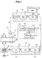
- Fig. 1 With reference to the drawings, and in particular to Fig. 1, there is shown a schematic diagram of a welding management apparatus embodying the invention.
- the tube production machine generally designated by the numeral 10, employs forming rollers arranged in a number of stages to form a workpiece 1 fed from a roll of metal strip in a tubular formation.
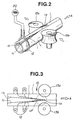
- a pair of squeeze rollers 13a and 13b are positioned on the opposite sides of the workpiece 1 and they provide an upsetting pressure to joint the opposite side surfaces of the workpiece 1 at a jointing point 1a just upstream of a point intermediate between the squeeze rollers 13a and 13b, as best shown in Fig. 2.
- a heating coil 12 is positioned to surround the workpiece 1 at a position upstream of the jointing point 1a.
- the heating coil 12 is supplied with a high frequency power to produce a highly concentrated, rapidly alternating magnetic field so as to induce an electric potential in the workpiece 1. This electric potential causes heating because of I2 ⁇ R losses at a welding point just downstream of the jointing point 1a where the opposite side surfaces 1b and 1c of the workpiece 1 are welded, as best shown in Fig. 2.
- the V-shaped gap which is defined near the jointing point 1a by the opposite side surfaces 1b and 1c of the workpiece 1, is referred to as a V throat.
- the heating coil 12 is powered from a high frequency power source 20 through a power control circuit 22.
- the welding heat under which the workpiece 1 is welded at the welding point 1a is determined from calculations performed in a control unit 30.
- a camera 40 is positioned above the workpiece 1.
- the camera 40 which may be of the type having an M x N array of CCD elements, is directed to have a visual field VF including the jointing (or welding) point 1a, as shown in Fig. 3.
- Fig. 4 shows a welding condition which may appear in the vidual field VF of the camera 40. In this welding condition, the opposite side surfaces 1b and 1c are connected by melted metal 2 at a point 2a upstream of the jointing point 1a.
- the melted metal 2 moves violently between the points 1a and 2a and it cannot cover the whole area between the points 1a and 2c to form an aperture 3 behind the melted metal 2.
- An arc (referred to as pre-arc) occurs frequently at the point 2a.
- This welding condition results from an excessive welding heat.
- the camera 40 is fixed certainly to suppress the movement of the vidual field VF within 0.1 mm at maximum. Noise will be introduced when the measuring point moves due to vibrations in the camera 40. It is also preferable that the introduced noise is less than 100 ⁇ m.
- the image (luminance level pattern) formed on the CCD elements is scanned in a series of raster scan lines and converted into a video signal S1 for application to the image processing unit 50. It is to be understood that the image formed on the CCD elements has synthetical information on which various welding conditions are reflected.
- the image processing unit 50 receives a video signal from the camera 40 and digitally stores the inputted image.
- the stored image A is represented by an M x N array of pixels. Each pixel A(x,y) is assigned a value representation of its intensity.
- the image processing unit 50 scans the stored image A in a series of raster scan lines to convert it into a black/white image B represented by an array of pixels. Each pixel B(x,y) has a value of 0 or 1.
- the image processing unit 51 may be arranged to differentiate the signal obtained when the stored image A is scanned in a series of raster scan lines and to convert the differentiated signal into the black/white image B.
- the image processing unit 50 counts the number of white pixels of the stored image B and produces an electric signal S5 corresponding to the counted white pixel number.
- the electric signal S5 represents the white area of the stored image B and, thus, the intensity of the welding heat.
- the image processing unit 50 may be arranged to produce the electric signal S5 by counting the number of white pixels arranged to form a longitudinal center line on the stored image.
- the camera 40 has such a resolving power that the number of the pixels forming the white area (in this case pre-arc area) is 100 or more.
- the image processing unit 50 may include an analog-to-digital converter (A/D) 52 which receives the video signal S1 from the camera 40 and converts it into digital form having 128 (0 to 127) tones. That is, the luminance level (Cd/M2) taken for each of the M x N array of CCD elements is converted into the corresponding digital signal.
- the digital signal S2 is applied from the A/D converter 52 to a first image memory (MEM) 54 which digitally stores an image of the visual field represented by an M x N array of pixels. Each pixel is assigned a value representative of its intensity (darkness).
- the stored image is scanned in a series of raster scan lines to convert it into a luminance (gray histogram) pattern.
- FIG. 5 shows one example of such a luminance pattern obtained for the welding condition described in connection with Fig. 4.
- the first luminous area surrounded by the circle P1 has the highest luminance level and it corresponds to the pre-arc produced at the point 2a.
- the second luminous area surrounded by the circles P1 and P2 has a luminance level less than the first luminous area and it corresponds to the workpiece portion surrounding the pre-arc.
- the letter G indicates the center of gravity of the first luminous area surrounded by the circle P1.
- the image processing unit 50 also includes a second image memory (MEM) 56 which stores reference luminance patterns.
- the digital computer (CPU) 58 makes a determination as to whether or not the welding condition is appropriate by comparing the luminance pattern S3 transferred thereto from the first image memory 54 with the reference image patterns S4 successively transferred thereinto from the second image memory 56.
- the digital computer 58 may be arranged to compare the first luminous area surrounded by the circle P1 with the corresponding area of each of the reference luminance patterns.
- the first luminous area surrounded by the circle P1 corresponds to the area of the pre-arc produced at the point 2c and it corresponds to the intensity of the welding heat.
- the digital computer 58 may be arranged to compare the longitudinal length of the first luminous area surrounded by the circle P1 with the corresponding length of each of the reference luminance patterns.
- the longitudinal length of the first luminous area surrounded by the circle P1 corresponds to the length of the melted metal 2 and it corresponds to the intensity of the welding heat.
- the digital computer 58 produces a decision signal S5 indicative of the result of the comparison made in the image processing unit 50.
- the decision signal S5 is fed from the image processing unit 50 to the control unit 30.
- the control unit 30 includes a correction factor calculating circuit (COR) 32, a signal converter circuit (CON) 34 and a signal control circuit (SCC) 36.
- the correction factor calculating circuit 32 receives the decision signal S5 from the digital computer 58 and a welding condition signal S9 and it calculates a correction factor based upon the received signals S5 and S9.
- the welding condition signal S9 may a sensor signal indicative of at least one of the measured values of high frequency power, high frequency impedance, welding rate, workpiece width, workpiece thickness, workpiece resistance, and the like parameters having an influence on the welding quality.
- the correction factor calculating circuit 32 produces a signal S6 indicating the calculated correction factor.
- the signal S6 is fed from the correction factor calculating circuit 32 to the signal converter circuit 34 which converts it into an electric signal S7.
- the electric signal S7 is applied to the signal control circuit 36 which compares it with a power setting reference signal S0 to produce a control signal S8 causing the power control circuit 22 to control the high frequency power to the heating coil 12.
- the welding management apparatus also includes an inference section 60 and a monitor section 62.
- the monitor section 62 includes display and alarm units 64 and 66 connected to the inference section 60.
- the inference section 60 receives the signals S5 and S9 and infers the welding condition.
- the inference section 60 may ba arranged to utilize the area, length, circumference, inclination angle of the first luminous area obtained by the digital computer 58 to infer the welding condition.
- the inferred welding condition is presented on the display unit 64.
- the alarm unit 66 operates to provide an audible indication when the inferred welding condition is defective.
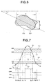
- the image processing unit 50 may be arranged to process the inputted image so as to provide an oval area Ao equivalent to the first luminous area Ap corresponding to the pre-arc, as shown in Fig. 6.
- the image processing unit 50 extracts at least one of characteristic features including the area of the equivalent oval area Ao, the length a of the major axis of the equivalent oval area Ao, the length b of the minor axis of the equivalent oval area Ao, the angle ⁇ of inclination of the equivalent oval area Ao, the position of the gravity center of the equivalent oval area Ao, the length of the circumference of the equivalent oval area Ao, etc.
- the area of the equivalent oval area Ao corresponds to the magnitude of the heat (welding heat) inputted to the workpiece 1.
- the number of the pixels forming the first luminous area Ao was 146 when the inputted heat is at its lower limit and was 950 when the input heat is at its upper limit.
- the angle ⁇ of inclination of the equivalent oval area Ao may be used to determine whether the workpiece is formed well symmetrically.
- the position of the gravity center of the equivalent oval area Ao corresponds to the angle of the V throat defined by the opposite side surfaces 1b and 1c of the workpiece 1.
- the characteristic feature is the position of the gravity center of the equivalent oval area Ao.
- the inference section 60 compares this characteristic feature hysteretically with a higher value L2 (100 pixels) of the lower limit when the characteristic feature is increasing and with a lower value L1 (80 pixels) of the lower limit when the characteristic feature is decreasing, as shown in Fig. 7.
- the inference section 60 compares the characteristic feature hysteretically with a higher value L4 (400 pixels) when the characteristic feature is increasing and with a lower value L3 (350 pixels) when the characteristic feature is decreasing.
- No alarm is produced from the alarm unit 66 as long as the characteristic feature varies within the acceptable range defined between the upper and lower limits, as indicated by the curve Co of Fig. 7. If the characteristic feature is out of the acceptable range, as indicated by the curve C1 of Fig. 7, the inference section 60 produces a command causing the alarm unit 66 to produce an alarm so as to indicate that the welding condition is defective.
- the inference section 60 may be arranged to infer a cause of the defective welding condition based upon the characteristic feature changing out of the acceptable range defined between the upper and lower limits. In this case, the inference section 60 indicates the inferred cause on the display unit 64.
- the invention is also applicable to another type of welding machine as shown in Fig. 8.
- This welding machine includes a pair of contacts 14a and 14b placed in contact with the workpiece 1 on the opposite sides of a line along which welding is required.
- the contacts 14a and 14b are supplied with a high frequency power to produce an electric potential in the workpiece 1. This electric potential causes heating because of I2R losses at the jointing point 1a where the opposite side surfaces 1b and 1c of the workpiece 1 are welded.
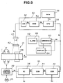
- FIG. 9 there is illustrated a second embodiment of the welding management apparatus of the invention.
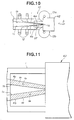
- the second embodiment is substantially the same as the first embodiment except for a masking member 42 provided in front of the camera 40 to mask the workpiece portion downstream of the welding point 1a.
- the luminous area corresponding to the heated portion of the workpiece 1 is divided into two portions 4a and 4b, as shown in Fig. 11.
- Fig. 12 shows one example of a luminance pattern obtained for the welding condition shown in Fig. 11.
- the area P1 corresponds to the area 4a of Fig. 11 and the area P2 corresponds to the area 4b of Fig. 11.
- the letter G1 indicates the center of gravity of the area 4a and the letter G2 indicates the center of gravity of the area 4b.
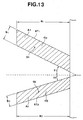
- the image processing unit 50 is arranged to process the inputted image so as to provide a trapezoid area AT1 equivalent to the area 4a and a trapezoid area AT2 equivalent to the area 4b, as shown in Fig. 13.
- the image processing unit 50 extracts the areas A1 and A2 of the respective trapezoid areas AT1 and AT2, the lengths a1 and a2 of the major axes of the respective trapezoid areas AT1 and AT2, the lengths b1 and b2 of the minor axes of the respective trapezoid areas AT1 and AT2, the positions G1 and G2 of the gravity centers of the respective trapezoid areas AT1 and AT2, and the angles ⁇ 1 and ⁇ 2 of inclination of the respective trapezoid areas AT1 and AT2.
- the image processing unit 50 superimposes at least one of characteristic features calculated as (A1 + A2)/2 , (A1 - A2)/(A1 + A2) 1/2 , (G1 + G2)/2 ,
- the characteristic feature (A1 + A2)/2 corresponds to the magnitude of the welding heat, the thickness of the workpiece 1 and the workpiece feeding speed.
- the characteristic feature (A1 - A2)/(A1 + A2) 1/2 corresponds to the degree to which the tubular formation of the workpiece 1 is balanced.
- the characteristic feature (G1 + G2)/2 corresponds to the upsetting pressure and the width of the workpiece 1.
- /(G1 x G2) 1/2 corresponds to the workpiece forming condition.
- )/( ⁇ 1 x ⁇ 2) 1/2 corresponds to the workpiece forming stability, workpiece thickness change and the degree to which the rollers are worn.
- the inference section 60 compares this characteristic feature hysteretically with a higher value L2 (400 pixels) of an upper limit when the characteristic feature is increasing and with a lower value L1 (350 pixels) of the upper limit when the characteristic feature is decreasing, as shown in Fig. 14. No alarm is produced from the alarm unit 66 as long as the characteristic feature varies below the upper limit, as indicated by the curve Co of Fig. 14. If the characteristic feature exceeds the upper limit, as indicated by the curve C1 of Fig. 14. the inference section 60 produces a command causing the alarm unit 66 to produce an alarm so as to indicate that the welding condition is defective.
- the inference section 60 may be arranged to infer a cause of the defective welding condition based upon the characteristic feature changing out of the acceptable range defined by the upper limit. In this case, the inference section 60 indicates the inferred cause on the display unit 64.
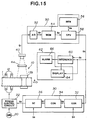
- FIG. 15 and 16 there is illustrated a third embodiment of the welding management apparatus of the invention.
- the third embodiment is substantially the same as the first embodiment except for a masking member 44 provided in front of the camera 40.
- the masking member 44 has a rectangular transparent window 44a.
- the transparent window 44a has parallel lines V1-V2, V3-V4 and V5-V6 to divide vidual field (VF), that is, the area of the transparent window 44a, into three zones V, E and F, as best shown in Fig. 17. These lines extend over the full length of the width of the transparent window in a direction normal to the workpiece feeding direction A, as best shown in Fig. 17.
- the line V1-V2 extends through the jointing point 1a of the workpiece 1.
- the V zone (center zone) is defined between the line V3-V4 and the line V5-V6.
- the E zone which is defined between the line V3-V4 and the window edge line E1-E2, is positioned on the downstream side of the V zone.
- the F zone which is defined between the line V5-V6 and the window edge line F1-F2, is positioned on the upstream side of the V zone.
- the line C1-C2 extends through the jointing point 1a in the workpiece feeding direction.
- One of the workpiece side surfaces is indicated by the line C1-B1 extending at an angle ⁇ 1 with respect to the line C1-C2.
- Fig. 18 shows one example of luminance distribution patterns obtained for the welding condition shown in Fig. 17.
- the luminance distribution pattern including areas P11 and p12 correspond to the F zone of Fig. 17, the luminance distribution pattern including an area P20 corresponds to the V zone of Fig. 17, and the luminance distribution pattern including an area P30 corresponds to the E zone of Fig. 17.
- the image processing unit 50 is arranged to extract at least one of the following characteristic features:
- the inference section 60 compares this characteristic feature hysteretically with a higher value L2 (100 pixels) of the lower limit when the characteristic feature is increasing and with a lower value L1 (80 pixels) of the lower limit when the characteristic feature is decreasing, as shown in Fig. 19. Similarly, the inference section 60 compares the characteristic feature hysteretically with a higher value L4 (400 pixels) when the characteristic feature is increasing and with a lower value L3 (350 pixels) when the characteristic feature is decreasing. No alarm is produced from the alarm unit 66 as long as the characteristic feature varies within tie acceptable range defined between the upper and lower limits, as indicated by the curve Co of Fig. 19. If the characteristic feature is out of the acceptable range, as indicated by the curve C1 of Fig. 19, the inference section 60 produces a command causing the alarm unit 66 to produce an alarm so as to indicate that the welding condition is defective.
- the inference section 60 may be arranged to infer a cause of the defective welding condition based upon the characteristic feature changing out of the acceptable range defined between the upper and lower limits. In this case, the inference section 60 indicates the inferred cause on the display unit 64.
Abstract
Description
- This invention relates to a welding management apparatus suitable for use with a tube production machine.
- Tube production machines have been employed to produce a metal tube member by forming a workpiece fed from a roll of metal strip in a tubular formation having side surfaces opposite to each other, providing an upsetting pressure to butt the opposite side surface of the workpiece at a jointing point, and supplying a high frequency power to the workpiece to weld the opposite side surfaces at a welding point. It is the conventional practice to adjust the intensity of the welding heat generated at and near the jointing point by controlling the high frequency power to the workpiece based upon various tube producing conditions that are sensed during the operation of the tube production machine. However, the welding heat intensity is dependent upon a great number of tube producing conditions. It is very difficult, if not impossible, to adjust the welding heat intensity based upon all of the tube producing conditions.
- It is an object of the invention to provide a welding management apparatus which can achieve excellent welding heat control with ease.
- There is provided, in accordance with the invention, a welding management apparatus for use with a tube production machine including first means for forming a workpiece fed from a roll of metal strip in a tubular formation having side surfaces opposite to each other, second means for providing an upsetting pressure to joint the opposite side surfaces of the workpiece at a jointing point, and third means for supplying a high frequency power to the workpiece to weld the opposite side surfaces at the jointing point so as to produce a metal tube member. The welding management apparatus comprises a camera positioned to have a visual field including the jointing point for producing a video signal indicative of an image including an area luminous with a pre-arc produced in the visual field, an image processor for converting the video signal into a luminance distribution pattern, and an inference unit for inferring a defective welding condition based upon the luminance distribution pattern. The inference unit includes means for producing an alarm when a defective welding condition is inferred.
- In another aspect of the invention, there is provided a welding management apparatus for use with a tube production machine including first means for forming a workpiece fed from a roll of metal strip in a tubular formation having side surfaces opposite to each other, second means for providing an upsetting pressure to joint the opposite side surfaces of the workpiece at a jointing point, and third means for supplying a high frequency power to the workpiece to weld the opposite side surfaces at the jointing point so as to produce a metal tube member. The welding management apparatus comprises a camera positioned to have a visual field including the jointing point for producing a video signal indicative of an image including an area luminous with heat produced in the visual field, a masking member placed in front of the camera for partially masking the visual field from the camera to divide the luminous area into first and second sections corresponding to the respective side surfaces of the workpiece, an image processor for converting the video signal fed from the camera into a luminance distribution pattern, and an inference unit for inferring a defective welding condition based upon the luminance distribution pattern.
- In another aspect of the invention, there is provided a welding management apparatus for use with a tube production machine including first means for forming a workpiece fed from a roll of metal strip in a tubular formation having side surfaces opposite to each other, second means for providing an upsetting pressure to joint the opposite side surfaces of the workpiece at a jointing point, and third means for supplying a high frequency power to the workpiece to weld the opposite side surfaces at the jointing point so as to produce a metal tube member. The welding management apparatus comprises a camera positioned to have a visual field including the jointing point for producing a video signal indicative of an image including an area luminous with heat produced in the visual field, a masking member placed in front of the camera, the masking member having a transparent window having lines extending in spaced-parallel relation to each other in a direction substantially normal to a direction of movement of the workpiece for dividing the visual field into a plurality of zones, an image processor for converting the video signal fed from the camera into luminance distribution patterns corresponding to the respective zones, and an inference unit for inferring a defective welding condition based upon the luminance distribution patterns.
- This invention will be described in greater detail by reference to the following description taken in connection with the accompanying drawings, in which:
- Fig. 1 is a schematic block diagram showing one embodiment of a welding management apparatus made in accordance with the invention;
- Fig. 2 is a fragmentary perspective view showing the welding section included in a tube production machine to which the invention is applicable;
- Fig. 3 is a fragmentary plan view showing a visual field of a camera used in the welding management apparatus of the invention;
- Fig. 4 is a fragmentary plan view showing a welding heat condition which may appear in the visual field of the camera;
- Fig. 5 is a diagram showing a luminance distribution pattern produced in the image processor;
- Fig. 6 is a diagram used in explaining the operation of the image processor;
- Fig. 7 is a diagram used in explaining the process for producing an alarm;
- Fig. 8 is a fragmentary perspective view showing another type of welding section included in the tube production machine to which the invention is applicable;
- Fig. 9 is a schematic block diagram showing a second embodiment of the welding management apparatus of the invention;
- Fig. 10 is a fragmentary plan view showing a visual field of a camera used in the welding management apparatus of the invention;
- Fig. 11 is a fragmentary plan view showing a welding heat condition which may appear in the visual field of the camera;
- Fig. 12 is a diagram showing a luminance distribution pattern produced in the image processor;
- Fig. 13 is a diagram used in explaining the operation of the image processor;
- Fig. 14 is a diagram used in explaining the process for producing an alarm;
- Fig. 15 is a schematic block diagram showing a third embodiment of the welding management apparatus of the invention;
- Fig. 16 is a fragmentary plan view showing a visual field of a camera used in the welding management apparatus of the invention;
- Fig. 17 is a fragmentary plan view showing a welding heat condition which may appear in the visual field of the camera;
- Fig. 18 is a diagram showing a luminance distribution pattern produced in the image processor;
- Fig. 19 is a diagram used in explaining the process for producing an alarm.
- With reference to the drawings, and in particular to Fig. 1, there is shown a schematic diagram of a welding management apparatus embodying the invention. Although the welding management apparatus will be described in connection with a tube production machine employing a high frequency induction welding unit, as shown in Fig. 2, it is to be understood that the invention is also applicable to other types of tube production machine. The tube production machine, generally designated by the
numeral 10, employs forming rollers arranged in a number of stages to form aworkpiece 1 fed from a roll of metal strip in a tubular formation. A pair ofsqueeze rollers workpiece 1 and they provide an upsetting pressure to joint the opposite side surfaces of theworkpiece 1 at a jointing point 1a just upstream of a point intermediate between thesqueeze rollers heating coil 12 is positioned to surround theworkpiece 1 at a position upstream of the jointing point 1a. Theheating coil 12 is supplied with a high frequency power to produce a highly concentrated, rapidly alternating magnetic field so as to induce an electric potential in theworkpiece 1. This electric potential causes heating because of I²·R losses at a welding point just downstream of the jointing point 1a where the opposite side surfaces 1b and 1c of theworkpiece 1 are welded, as best shown in Fig. 2. The V-shaped gap, which is defined near the jointing point 1a by the opposite side surfaces 1b and 1c of theworkpiece 1, is referred to as a V throat. - The
heating coil 12 is powered from a highfrequency power source 20 through apower control circuit 22. The welding heat under which theworkpiece 1 is welded at the welding point 1a, this being determined by the level of the power applied to theheating coil 12, is determined from calculations performed in acontrol unit 30. Acamera 40 is positioned above theworkpiece 1. Thecamera 40, which may be of the type having an M x N array of CCD elements, is directed to have a visual field VF including the jointing (or welding) point 1a, as shown in Fig. 3. Fig. 4 shows a welding condition which may appear in the vidual field VF of thecamera 40. In this welding condition, the opposite side surfaces 1b and 1c are connected by meltedmetal 2 at a point 2a upstream of the jointing point 1a. The meltedmetal 2 moves violently between the points 1a and 2a and it cannot cover the whole area between the points 1a and 2c to form anaperture 3 behind the meltedmetal 2. An arc (referred to as pre-arc) occurs frequently at the point 2a. This welding condition results from an excessive welding heat. Preferably, thecamera 40 is fixed certainly to suppress the movement of the vidual field VF within 0.1 mm at maximum. Noise will be introduced when the measuring point moves due to vibrations in thecamera 40. It is also preferable that the introduced noise is less than 100 µm. - The image (luminance level pattern) formed on the CCD elements is scanned in a series of raster scan lines and converted into a video signal S1 for application to the
image processing unit 50. It is to be understood that the image formed on the CCD elements has synthetical information on which various welding conditions are reflected. Theimage processing unit 50 receives a video signal from thecamera 40 and digitally stores the inputted image. The stored image A is represented by an M x N array of pixels. Each pixel A(x,y) is assigned a value representation of its intensity. Theimage processing unit 50 scans the stored image A in a series of raster scan lines to convert it into a black/white image B represented by an array of pixels. Each pixel B(x,y) has a value of 0 or 1.

image processing unit 50 counts the number of white pixels of the stored image B and produces an electric signal S5 corresponding to the counted white pixel number. The electric signal S5 represents the white area of the stored image B and, thus, the intensity of the welding heat. Theimage processing unit 50 may be arranged to produce the electric signal S5 by counting the number of white pixels arranged to form a longitudinal center line on the stored image. Preferably, thecamera 40 has such a resolving power that the number of the pixels forming the white area (in this case pre-arc area) is 100 or more. - The
image processing unit 50 may include an analog-to-digital converter (A/D) 52 which receives the video signal S1 from thecamera 40 and converts it into digital form having 128 (0 to 127) tones. That is, the luminance level (Cd/M²) taken for each of the M x N array of CCD elements is converted into the corresponding digital signal. The digital signal S2 is applied from the A/D converter 52 to a first image memory (MEM) 54 which digitally stores an image of the visual field represented by an M x N array of pixels. Each pixel is assigned a value representative of its intensity (darkness). The stored image is scanned in a series of raster scan lines to convert it into a luminance (gray histogram) pattern. Fig. 5 shows one example of such a luminance pattern obtained for the welding condition described in connection with Fig. 4. The first luminous area surrounded by the circle P1 has the highest luminance level and it corresponds to the pre-arc produced at the point 2a. The second luminous area surrounded by the circles P1 and P2 has a luminance level less than the first luminous area and it corresponds to the workpiece portion surrounding the pre-arc. In Fig. 5, the letter G indicates the center of gravity of the first luminous area surrounded by the circle P1. - The
image processing unit 50 also includes a second image memory (MEM) 56 which stores reference luminance patterns. The digital computer (CPU) 58 makes a determination as to whether or not the welding condition is appropriate by comparing the luminance pattern S3 transferred thereto from thefirst image memory 54 with the reference image patterns S4 successively transferred thereinto from thesecond image memory 56. For this purpose, thedigital computer 58 may be arranged to compare the first luminous area surrounded by the circle P1 with the corresponding area of each of the reference luminance patterns. The first luminous area surrounded by the circle P1 corresponds to the area of the pre-arc produced at the point 2c and it corresponds to the intensity of the welding heat. Alternatively, thedigital computer 58 may be arranged to compare the longitudinal length of the first luminous area surrounded by the circle P1 with the corresponding length of each of the reference luminance patterns. The longitudinal length of the first luminous area surrounded by the circle P1 corresponds to the length of the meltedmetal 2 and it corresponds to the intensity of the welding heat. Thedigital computer 58 produces a decision signal S5 indicative of the result of the comparison made in theimage processing unit 50. The decision signal S5 is fed from theimage processing unit 50 to thecontrol unit 30. - The
control unit 30 includes a correction factor calculating circuit (COR) 32, a signal converter circuit (CON) 34 and a signal control circuit (SCC) 36. The correctionfactor calculating circuit 32 receives the decision signal S5 from thedigital computer 58 and a welding condition signal S9 and it calculates a correction factor based upon the received signals S5 and S9. The welding condition signal S9 may a sensor signal indicative of at least one of the measured values of high frequency power, high frequency impedance, welding rate, workpiece width, workpiece thickness, workpiece resistance, and the like parameters having an influence on the welding quality. The correctionfactor calculating circuit 32 produces a signal S6 indicating the calculated correction factor. The signal S6 is fed from the correctionfactor calculating circuit 32 to thesignal converter circuit 34 which converts it into an electric signal S7. The electric signal S7 is applied to thesignal control circuit 36 which compares it with a power setting reference signal S0 to produce a control signal S8 causing thepower control circuit 22 to control the high frequency power to theheating coil 12. - The welding management apparatus also includes an
inference section 60 and amonitor section 62. Themonitor section 62 includes display andalarm units inference section 60. Theinference section 60 receives the signals S5 and S9 and infers the welding condition. Theinference section 60 may ba arranged to utilize the area, length, circumference, inclination angle of the first luminous area obtained by thedigital computer 58 to infer the welding condition. The inferred welding condition is presented on thedisplay unit 64. Thealarm unit 66 operates to provide an audible indication when the inferred welding condition is defective. - The
image processing unit 50 may be arranged to process the inputted image so as to provide an oval area Ao equivalent to the first luminous area Ap corresponding to the pre-arc, as shown in Fig. 6. Theimage processing unit 50 extracts at least one of characteristic features including the area of the equivalent oval area Ao, the length a of the major axis of the equivalent oval area Ao, the length b of the minor axis of the equivalent oval area Ao, the angle ϑ of inclination of the equivalent oval area Ao, the position of the gravity center of the equivalent oval area Ao, the length of the circumference of the equivalent oval area Ao, etc. The area of the equivalent oval area Ao corresponds to the magnitude of the heat (welding heat) inputted to theworkpiece 1. For example, the number of the pixels forming the first luminous area Ao was 146 when the inputted heat is at its lower limit and was 950 when the input heat is at its upper limit. The angle ϑ of inclination of the equivalent oval area Ao may be used to determine whether the workpiece is formed well symmetrically. The position of the gravity center of the equivalent oval area Ao corresponds to the angle of the V throat defined by the opposite side surfaces 1b and 1c of theworkpiece 1. These characteristic features are presented on thedisplay unit 64. Theinference section 60 receives the extracted characteristic feature from theimage processing unit 50 and compares the received characteristic feature with upper and lower limits. If the received characteristic feature is out of the range defined by the upper and lower limits, theinference section 60 produces a command causing thealarm unit 66 to produce an audible indication. - It is now assumed that the characteristic feature is the position of the gravity center of the equivalent oval area Ao. The
inference section 60 compares this characteristic feature hysteretically with a higher value L2 (100 pixels) of the lower limit when the characteristic feature is increasing and with a lower value L1 (80 pixels) of the lower limit when the characteristic feature is decreasing, as shown in Fig. 7. Similarly, theinference section 60 compares the characteristic feature hysteretically with a higher value L4 (400 pixels) when the characteristic feature is increasing and with a lower value L3 (350 pixels) when the characteristic feature is decreasing. No alarm is produced from thealarm unit 66 as long as the characteristic feature varies within the acceptable range defined between the upper and lower limits, as indicated by the curve Co of Fig. 7. If the characteristic feature is out of the acceptable range, as indicated by the curve C1 of Fig. 7, theinference section 60 produces a command causing thealarm unit 66 to produce an alarm so as to indicate that the welding condition is defective. - The
inference section 60 may be arranged to infer a cause of the defective welding condition based upon the characteristic feature changing out of the acceptable range defined between the upper and lower limits. In this case, theinference section 60 indicates the inferred cause on thedisplay unit 64. - The invention is also applicable to another type of welding machine as shown in Fig. 8. This welding machine includes a pair of contacts 14a and 14b placed in contact with the
workpiece 1 on the opposite sides of a line along which welding is required. The contacts 14a and 14b are supplied with a high frequency power to produce an electric potential in theworkpiece 1. This electric potential causes heating because of I²R losses at the jointing point 1a where the opposite side surfaces 1b and 1c of theworkpiece 1 are welded. - Referring to Figs. 9 and 10, there is illustrated a second embodiment of the welding management apparatus of the invention. The second embodiment is substantially the same as the first embodiment except for a masking
member 42 provided in front of thecamera 40 to mask the workpiece portion downstream of the welding point 1a. With the use of the maskingmember 42, the luminous area corresponding to the heated portion of theworkpiece 1 is divided into twoportions area 4a of Fig. 11 and the area P2 corresponds to thearea 4b of Fig. 11. The letter G1 indicates the center of gravity of thearea 4a and the letter G2 indicates the center of gravity of thearea 4b. - In this embodiment, the
image processing unit 50 is arranged to process the inputted image so as to provide a trapezoid area AT1 equivalent to thearea 4a and a trapezoid area AT2 equivalent to thearea 4b, as shown in Fig. 13. Theimage processing unit 50 extracts the areas A1 and A2 of the respective trapezoid areas AT1 and AT2, the lengths a1 and a2 of the major axes of the respective trapezoid areas AT1 and AT2, the lengths b1 and b2 of the minor axes of the respective trapezoid areas AT1 and AT2, the positions G1 and G2 of the gravity centers of the respective trapezoid areas AT1 and AT2, and the angles ϑ1 and ϑ2 of inclination of the respective trapezoid areas AT1 and AT2. Theimage processing unit 50 superimposes at least one of characteristic features calculated as


workpiece 1 and the workpiece feeding speed. The characteristic feature
workpiece 1 is balanced. The characteristic feature
workpiece 1. The characteristic feature

- It is now assumed that the characteristic feature is the position of the gravity center of the equivalent area. The
inference section 60 compares this characteristic feature hysteretically with a higher value L2 (400 pixels) of an upper limit when the characteristic feature is increasing and with a lower value L1 (350 pixels) of the upper limit when the characteristic feature is decreasing, as shown in Fig. 14. No alarm is produced from thealarm unit 66 as long as the characteristic feature varies below the upper limit, as indicated by the curve Co of Fig. 14. If the characteristic feature exceeds the upper limit, as indicated by the curve C1 of Fig. 14. theinference section 60 produces a command causing thealarm unit 66 to produce an alarm so as to indicate that the welding condition is defective. Theinference section 60 may be arranged to infer a cause of the defective welding condition based upon the characteristic feature changing out of the acceptable range defined by the upper limit. In this case, theinference section 60 indicates the inferred cause on thedisplay unit 64. - Referring to Figs. 15 and 16, there is illustrated a third embodiment of the welding management apparatus of the invention. The third embodiment is substantially the same as the first embodiment except for a masking
member 44 provided in front of thecamera 40. The maskingmember 44 has a rectangular transparent window 44a. The transparent window 44a has parallel lines V1-V2, V3-V4 and V5-V6 to divide vidual field (VF), that is, the area of the transparent window 44a, into three zones V, E and F, as best shown in Fig. 17. These lines extend over the full length of the width of the transparent window in a direction normal to the workpiece feeding direction A, as best shown in Fig. 17. The line V1-V2 extends through the jointing point 1a of theworkpiece 1. The V zone (center zone) is defined between the line V3-V4 and the line V5-V6. The E zone, which is defined between the line V3-V4 and the window edge line E1-E2, is positioned on the downstream side of the V zone. The F zone, which is defined between the line V5-V6 and the window edge line F1-F2, is positioned on the upstream side of the V zone. The line C1-C2 extends through the jointing point 1a in the workpiece feeding direction. One of the workpiece side surfaces is indicated by the line C1-B1 extending at an angle ϑ1 with respect to the line C1-C2. The other workpiece side surface is indicated by the line C1-B1 extending at an angle ϑ2 with respect to the line C1-C2. With the use of the maskingmember 44, the luminous area corresponding to the heated portion of theworkpiece 1 is divided into three zones. Fig. 18 shows one example of luminance distribution patterns obtained for the welding condition shown in Fig. 17. The luminance distribution pattern including areas P11 and p12 correspond to the F zone of Fig. 17, the luminance distribution pattern including an area P20 corresponds to the V zone of Fig. 17, and the luminance distribution pattern including an area P30 corresponds to the E zone of Fig. 17. - In this embodiment, the
image processing unit 50 is arranged to extract at least one of the following characteristic features: - (1) The area of the luminous area of the sum of the F, V and E zones, the position of the gravity center of the luminous area of the sum of the F, V and E zones, the length of the circumference of the luminous area of the sum of the F, V and E zones. These characteristic features correspond to the inputted (welding) heat.
- (2) The angle ϑ1 and ϑ2 of the lines B1-C1 and B2-C1 with respect to the line C1-C2. To obtain the lines B1-C1 and B2-C1, the image in the area V5-V6-F2-F1 may be differentiated. The areas A1 and A2 of the
luminous areas - (3) The position of the gravity center of the area V3-V4-V6-V5. This characteristic feature corresponds to the magnitude of the upsetting pressure.
- (4) The image in the area E1-E2-V4-V3 is differentiated to determine the presence of slits. If slits are produced frequency, it will mean that the inputted (welding) heat is excessive.
- It is now assumed that the characteristic feature is the position of the gravity center. The
inference section 60 compares this characteristic feature hysteretically with a higher value L2 (100 pixels) of the lower limit when the characteristic feature is increasing and with a lower value L1 (80 pixels) of the lower limit when the characteristic feature is decreasing, as shown in Fig. 19. Similarly, theinference section 60 compares the characteristic feature hysteretically with a higher value L4 (400 pixels) when the characteristic feature is increasing and with a lower value L3 (350 pixels) when the characteristic feature is decreasing. No alarm is produced from thealarm unit 66 as long as the characteristic feature varies within tie acceptable range defined between the upper and lower limits, as indicated by the curve Co of Fig. 19. If the characteristic feature is out of the acceptable range, as indicated by the curve C1 of Fig. 19, theinference section 60 produces a command causing thealarm unit 66 to produce an alarm so as to indicate that the welding condition is defective. - The
inference section 60 may be arranged to infer a cause of the defective welding condition based upon the characteristic feature changing out of the acceptable range defined between the upper and lower limits. In this case, theinference section 60 indicates the inferred cause on thedisplay unit 64.
Claims (16)
- A welding management apparatus for use with a tube production machine (10) including first means for forming a workpiece (1) fed from a roll of metal strip in a tubular formation having side surfaces (1b, 1c) opposite to each other, second means (13a, 13b) for providing an upsetting pressure to joint the opposite side surfaces (1b, 1c) of the workpiece (1) at a jointing point (1a), and third means (20) for supplying a high frequency power to the workpiece (1) to weld the opposite side surfaces (1b, 1c) at the jointing point (1a) so as to produce a metal tube member, the welding management apparatus comprising:
a camera (40) positioned to have a visual field (VF) including the jointing point (1a) for producing a video signal (S1) indicative of an image including an area luminous with a pre-arc produced in the visual field;
an image processor (50) for converting the video signal (S1) into a luminance distribution pattern; and
an inference unit (60) for inferring a defective welding condition based upon the luminance distribution pattern, the inference unit (60) including means for producing an alarm when a defective welding condition is inferred. - The welding management apparatus as claimed in claim 1, wherein the image processor (50) includes means for extracting at least one of characteristic features of the luminance distribution pattern, and wherein the inference unit (60) includes means for producing an alarm when the extracted characteristic feature is out of an acceptable range.
- The welding management apparatus as claimed in claim 2, further comprising means for inferring a cause of the defective welding condition based upon the characteristic feature changing out of the acceptable range.
- The welding management apparatus as claimed in claim 3, wherein the image processor (50) includes means for producing an oval area (Ao) equivalent to the luminous area (Ap), and wherein the characteristic feature include one of the area of the equivalent oval area (Ao), the length (a) of the major axis of the equivalent oval area (Ao), the length (b) of the minor axis of the equivalent oval area (Ao), the position of the gravity center of the equivalent oval area (Ao), the length of the circumference of the equivalent oval area (Ao), and the angle (Θ) of inclination of the equivalent oval area (Ao).
- The welding management apparatus as claimed in claim 2, wherein the image processor (50) includes means for producing an oval area (Ao) equivalent to the luminous area (Ap), and wherein the characteristic feature include one of the area of the equivalent oval area (Ao), the length (a) of the major axis of the equivalent oval area (Ao), the length (b) of the minor axis of the equivalent oval area (Ao), the position of the gravity center of the equivalent oval area (Ao), the length of the circumference of the equivalent oval area (Ao), and the angle (Θ) of inclination of the equivalent oval area (Ao).
- The welding management apparatus as claimed in claim 1, further comprising means for making a comparison of the luminance pattern with at least one reference pattern, and means for controlling the third means to adjust the high frequency power based upon the comparison.
- A welding management apparatus for use with a tube production machine including first means for forming a workpiece (1) fed from a roll of metal strip in a tubular formation having side surfaces (1b, 1c) opposite to each other, second means (13a, 13b) for providing an upsetting pressure to joint the opposite side surfaces (1b, 1c) of the workpiece (1) at a jointing point (1a), and third means (20) for supplying a high frequency power to the workpiece (1) to weld the opposite side surfaces (1b, 1c) at the jointing point (1a) so as to produce a metal tube member, the welding management apparatus comprising:
a camera (40) positioned to have a visual field (VF) including the jointing point (1a) for producing a video signal (S1) indicative of an image including an area luminous with heat produced in the visual field (VF);
a masking member (42) placed in front of the camera (40) for partially masking the visual field (VF) from the camera (40) to divide the luminous area into first and second sections (4a, 4b) corresponding to the respective side surfaces of the workpiece (1);
an image processor (50) for converting the video signal (S1) fed from the camera (40) into a luminance distribution pattern; and
an inference unit (60) for inferring a defective welding condition based upon the luminance distribution pattern. - The welding management apparatus as claimed in claim 7, wherein the inference unit (60) includes means (66) for producing an alarm when a defective welding condition is inferred.
- The welding management apparatus as claimed in claim 8, wherein the image processor (50) includes means for extracting at least one of characteristic features of the luminance distribution pattern, and wherein the inference unit (60) includes means (66) for producing an alarm when the extracted characteristic feature is out of an acceptable range.
- The welding management apparatus as claimed in claim 9, further comprising means for inferring a cause of the defective welding condition based upon the characteristic feature changing out of the acceptable range.
- The welding management apparatus as claimed in claim 7, further comprising means for making a comparison of the luminance pattern with at least one reference pattern, and means for controlling the third means to adjust the high frequency power based upon the comparison.
- A welding management apparatus for use with a tube production machine (10) including first means for forming a workpiece (1) fed from a roll of metal strip in a tubular formation having side surfaces (1b, 1c) opposite to each other, second means (13a, 13b) for providing an upsetting pressure to joint the opposite side surfaces (1b, 1c) of the workpiece (1) at a jointing point (1a), and third means for supplying a high frequency power to the workpiece (1) to weld the opposite side (1b, 1c) at the jointing point (1a) so as to produce a metal tube member, the welding management apparatus comprising:
a camera (40) positioned to have a visual field (VF) including the jointing point (1a) for producing a video signal (S1) indicative of an image including an area luminous with heat produced in the visual field;
a masking member (44) placed in front of the camera, the masking member (44) having a transparent window (44a) having lines (V1-V2, V3-V4, V5-V6) extending in spaced-parallel relation to each other in a direction substantially normal to a direction of movement of the workpiece (1) for dividing the visual field (VF) into a plurality of zones (V, E, F);
an image processor (50) for converting the video signal (S1) fed from the camera (40) into luminance distribution patterns corresponding to the respective zones (V, E, F); and
an inference unit (60) for inferring a defective welding condition based upon the luminance distribution patterns. - The welding management apparatus as claimed in claim 12, wherein the inference unit (60) includes means (66) for producing an alarm when a defective welding condition is inferred.
- The welding management apparatus as claimed in claim 13, wherein the image processor (50) includes means for extracting at least one of characteristic features of the respective luminance distribution patterns, and wherein the inference unit (60) includes means (66) for producing an alarm when the extracted characteristic feature is out of an acceptable range.
- The welding management apparatus as claimed in claim 14, further comprising means for inferring a cause of the defective welding condition based upon the characteristic feature changing out of the acceptable range.
- The welding management apparatus as claimed in claim 12, further comprising means for making a comparison of at least one of the luminance patterns with at least one reference pattern, and means for controlling the third means to adjust the high frequency power based upon the comparison.
Applications Claiming Priority (11)
| Application Number | Priority Date | Filing Date | Title |
|---|---|---|---|
| JP4066726A JP3052547B2 (en) | 1992-03-25 | 1992-03-25 | ERW pipe manufacturing equipment |
| JP66726/92 | 1992-03-25 | ||
| JP84264/92 | 1992-04-07 | ||
| JP4084264A JP3052555B2 (en) | 1992-04-07 | 1992-04-07 | Manufacturing method of small-diameter ERW pipe |
| JP4099372A JPH05293670A (en) | 1992-04-20 | 1992-04-20 | Method and device for monitoring resistance welded tube welding and control method for resistance welded tube welding |
| JP99372/92 | 1992-04-20 | ||
| JP4131264A JPH05318142A (en) | 1992-05-25 | 1992-05-25 | Method and device for monitoring resistance welded tube welding and resistance welded tube welding controller |
| JP131263/92 | 1992-05-25 | ||
| JP131264/92 | 1992-05-25 | ||
| JP4131263A JPH05318141A (en) | 1992-05-25 | 1992-05-25 | Method and device for monitoring resistance welded tube welding and resistance welded tube welding controller |
| EP93102179A EP0566834B1 (en) | 1992-03-25 | 1993-02-11 | Tube production machine |
Related Parent Applications (1)
| Application Number | Title | Priority Date | Filing Date |
|---|---|---|---|
| EP93102179.4 Division | 1993-02-11 |
Publications (2)
| Publication Number | Publication Date |
|---|---|
| EP0670194A1 true EP0670194A1 (en) | 1995-09-06 |
| EP0670194B1 EP0670194B1 (en) | 1997-09-17 |
Family
ID=27524003
Family Applications (2)
| Application Number | Title | Priority Date | Filing Date |
|---|---|---|---|
| EP95108472A Expired - Lifetime EP0670194B1 (en) | 1992-03-25 | 1993-02-11 | Welding management apparatus |
| EP93102179A Expired - Lifetime EP0566834B1 (en) | 1992-03-25 | 1993-02-11 | Tube production machine |
Family Applications After (1)
| Application Number | Title | Priority Date | Filing Date |
|---|---|---|---|
| EP93102179A Expired - Lifetime EP0566834B1 (en) | 1992-03-25 | 1993-02-11 | Tube production machine |
Country Status (8)
| Country | Link |
|---|---|
| US (2) | US5265787A (en) |
| EP (2) | EP0670194B1 (en) |
| KR (1) | KR960016155B1 (en) |
| CA (1) | CA2089849C (en) |
| DE (2) | DE69314052T2 (en) |
| ES (2) | ES2108516T3 (en) |
| MY (2) | MY113115A (en) |
| TW (1) | TW221384B (en) |
Cited By (2)
| Publication number | Priority date | Publication date | Assignee | Title |
|---|---|---|---|---|
| FR2763874A1 (en) * | 1997-05-15 | 1998-12-04 | Seah Steel Corp | Automatic control system for high frequency electric resistance welding |
| EP0934796A1 (en) * | 1998-02-06 | 1999-08-11 | Swisscab S.A. | Method of manufacturing a metallic tubular sheath wherein it is controlled that a defect-free weld has been made and apparatus for carrying out the method |
Families Citing this family (60)
| Publication number | Priority date | Publication date | Assignee | Title |
|---|---|---|---|---|
| US5560536A (en) * | 1995-02-14 | 1996-10-01 | Commscope, Inc. | Apparatus and method for making coaxial cable having longitudinally welded outer conductor |
| US5809162A (en) * | 1995-12-22 | 1998-09-15 | Lucent Technologies Inc. | Surface analysis system and method |
| US5632912A (en) * | 1995-06-16 | 1997-05-27 | Cecil; Dimitrios G. | Resistance projection welding system and method for welding a projection weld nut to a workpiece |
| US5645738A (en) * | 1995-09-15 | 1997-07-08 | Cecil; Dimitrios G. | Apparatus and method for resistance welding tubular parts |
| US5828028A (en) * | 1996-06-24 | 1998-10-27 | Cecil; Dimitrios G. | Hot forging method and apparatus |
| US5831235A (en) * | 1996-06-24 | 1998-11-03 | Cecil; Dimitrios G. | Apparatus and method of welding a tube and bracket assembly |
| ES2153795B1 (en) * | 1999-08-19 | 2001-08-16 | Gh Electrotermia S A | SYSTEM FOR HEATING BY INDUCTION AND SIMILAR, WITH MAINTENANCE ONLINE. |
| US6278077B1 (en) | 1999-12-02 | 2001-08-21 | Dimitrios G. Cecil | Weld indexing method and system |
| JP2003001323A (en) * | 2001-06-13 | 2003-01-07 | Mitsubishi Shindoh Co Ltd | Squeeze roll unit device for electric resistance welded pipe |
| US7181821B2 (en) * | 2002-07-17 | 2007-02-27 | Shell Oil Company | Joining expandable tubulars |
| CN100402222C (en) * | 2002-07-17 | 2008-07-16 | 国际壳牌研究有限公司 | Forge welding method |
| US20060169752A1 (en) * | 2002-07-17 | 2006-08-03 | Den Boer Johannis Josephus | Forge welding of heavy duty tubulars |
| DK1532474T3 (en) * | 2002-07-18 | 2012-10-01 | Shell Int Research | MARKING OF PIPE CONNECTIONS |
| US7282663B2 (en) * | 2002-07-29 | 2007-10-16 | Shell Oil Company | Forge welding process |
| US7774917B2 (en) * | 2003-07-17 | 2010-08-17 | Tubefuse Applications B.V. | Forge welding tubulars |
| US7683288B2 (en) * | 2005-08-12 | 2010-03-23 | Thermatool Corp. | System and method of computing the operating parameters of a forge welding machine |
| US9104195B2 (en) | 2006-12-20 | 2015-08-11 | Lincoln Global, Inc. | Welding job sequencer |
| US9937577B2 (en) | 2006-12-20 | 2018-04-10 | Lincoln Global, Inc. | System for a welding sequencer |
| US10994357B2 (en) | 2006-12-20 | 2021-05-04 | Lincoln Global, Inc. | System and method for creating or modifying a welding sequence |
| US11072034B2 (en) | 2006-12-20 | 2021-07-27 | Lincoln Global, Inc. | System and method of exporting or using welding sequencer data for external systems |
| US10994358B2 (en) | 2006-12-20 | 2021-05-04 | Lincoln Global, Inc. | System and method for creating or modifying a welding sequence based on non-real world weld data |
| US9280913B2 (en) | 2009-07-10 | 2016-03-08 | Lincoln Global, Inc. | Systems and methods providing enhanced education and training in a virtual reality environment |
| US9330575B2 (en) | 2008-08-21 | 2016-05-03 | Lincoln Global, Inc. | Tablet-based welding simulator |
| US8834168B2 (en) | 2008-08-21 | 2014-09-16 | Lincoln Global, Inc. | System and method providing combined virtual reality arc welding and three-dimensional (3D) viewing |
| US8915740B2 (en) * | 2008-08-21 | 2014-12-23 | Lincoln Global, Inc. | Virtual reality pipe welding simulator |
| US8747116B2 (en) * | 2008-08-21 | 2014-06-10 | Lincoln Global, Inc. | System and method providing arc welding training in a real-time simulated virtual reality environment using real-time weld puddle feedback |
| US8911237B2 (en) | 2008-08-21 | 2014-12-16 | Lincoln Global, Inc. | Virtual reality pipe welding simulator and setup |
| US8884177B2 (en) | 2009-11-13 | 2014-11-11 | Lincoln Global, Inc. | Systems, methods, and apparatuses for monitoring weld quality |
| US9196169B2 (en) | 2008-08-21 | 2015-11-24 | Lincoln Global, Inc. | Importing and analyzing external data using a virtual reality welding system |
| US8851896B2 (en) | 2008-08-21 | 2014-10-07 | Lincoln Global, Inc. | Virtual reality GTAW and pipe welding simulator and setup |
| US9318026B2 (en) | 2008-08-21 | 2016-04-19 | Lincoln Global, Inc. | Systems and methods providing an enhanced user experience in a real-time simulated virtual reality welding environment |
| US9483959B2 (en) * | 2008-08-21 | 2016-11-01 | Lincoln Global, Inc. | Welding simulator |
| US8274013B2 (en) | 2009-03-09 | 2012-09-25 | Lincoln Global, Inc. | System for tracking and analyzing welding activity |
| US9773429B2 (en) | 2009-07-08 | 2017-09-26 | Lincoln Global, Inc. | System and method for manual welder training |
| US9221117B2 (en) | 2009-07-08 | 2015-12-29 | Lincoln Global, Inc. | System for characterizing manual welding operations |
| US10748447B2 (en) | 2013-05-24 | 2020-08-18 | Lincoln Global, Inc. | Systems and methods providing a computerized eyewear device to aid in welding |
| US9011154B2 (en) | 2009-07-10 | 2015-04-21 | Lincoln Global, Inc. | Virtual welding system |
| US8569655B2 (en) | 2009-10-13 | 2013-10-29 | Lincoln Global, Inc. | Welding helmet with integral user interface |
| US9468988B2 (en) | 2009-11-13 | 2016-10-18 | Lincoln Global, Inc. | Systems, methods, and apparatuses for monitoring weld quality |
| US8569646B2 (en) | 2009-11-13 | 2013-10-29 | Lincoln Global, Inc. | Systems, methods, and apparatuses for monitoring weld quality |
| CA2821671C (en) | 2010-12-13 | 2018-01-09 | Edison Welding Institute, Inc. | Welding training system |
| US20160093233A1 (en) | 2012-07-06 | 2016-03-31 | Lincoln Global, Inc. | System for characterizing manual welding operations on pipe and other curved structures |
| US9767712B2 (en) | 2012-07-10 | 2017-09-19 | Lincoln Global, Inc. | Virtual reality pipe welding simulator and setup |
| CN104540632A (en) * | 2012-08-17 | 2015-04-22 | 新日铁住金株式会社 | Welding device for electric resistance welded pipe |
| US10930174B2 (en) | 2013-05-24 | 2021-02-23 | Lincoln Global, Inc. | Systems and methods providing a computerized eyewear device to aid in welding |
| US20150072323A1 (en) | 2013-09-11 | 2015-03-12 | Lincoln Global, Inc. | Learning management system for a real-time simulated virtual reality welding training environment |
| US10083627B2 (en) | 2013-11-05 | 2018-09-25 | Lincoln Global, Inc. | Virtual reality and real welding training system and method |
| US9836987B2 (en) | 2014-02-14 | 2017-12-05 | Lincoln Global, Inc. | Virtual reality pipe welding simulator and setup |
| WO2015185972A1 (en) | 2014-06-02 | 2015-12-10 | Lincoln Global, Inc. | System and method for manual welder training |
| US20160214200A1 (en) * | 2015-01-23 | 2016-07-28 | Illinois Tool Works Inc. | User Configuration of Image Capture and Display in a Welding Vision System |
| CN105215534B (en) * | 2015-11-13 | 2017-09-26 | 中冶赛迪工程技术股份有限公司 | A kind of high-frequency welding intelligence control system and method |
| EP3319066A1 (en) | 2016-11-04 | 2018-05-09 | Lincoln Global, Inc. | Magnetic frequency selection for electromagnetic position tracking |
| US10913125B2 (en) | 2016-11-07 | 2021-02-09 | Lincoln Global, Inc. | Welding system providing visual and audio cues to a welding helmet with a display |
| US10878591B2 (en) | 2016-11-07 | 2020-12-29 | Lincoln Global, Inc. | Welding trainer utilizing a head up display to display simulated and real-world objects |
| US10997872B2 (en) | 2017-06-01 | 2021-05-04 | Lincoln Global, Inc. | Spring-loaded tip assembly to support simulated shielded metal arc welding |
| US11557223B2 (en) | 2018-04-19 | 2023-01-17 | Lincoln Global, Inc. | Modular and reconfigurable chassis for simulated welding training |
| US11475792B2 (en) | 2018-04-19 | 2022-10-18 | Lincoln Global, Inc. | Welding simulator with dual-user configuration |
| CN110347093A (en) * | 2019-08-03 | 2019-10-18 | 山东大庚工程材料科技有限公司 | A kind of whole grid welding equipment control system of high-strength intelligence |
| CN111839120B (en) * | 2020-07-27 | 2021-06-25 | 苏州龙时汇达商业设备股份有限公司 | Liftable commodity show shelf based on internet live takes goods to use |
| CN112845640B (en) * | 2020-12-26 | 2023-01-03 | 开平市华灵管业有限公司 | Metal bellows expansion joint forming process device |
Citations (4)
| Publication number | Priority date | Publication date | Assignee | Title |
|---|---|---|---|---|
| JPS57206581A (en) * | 1981-06-11 | 1982-12-17 | Nippon Kokan Kk <Nkk> | Control method for welding heat input in production of electric welded pipe |
| FR2575686A1 (en) * | 1985-01-10 | 1986-07-11 | Nippon Steel Corp | HIGH FREQUENCY WELDING METHOD USING ELECTRIC RESISTANCE USING LASER BEAM EXPOSURE |
| EP0353409A1 (en) * | 1988-07-28 | 1990-02-07 | Oerlikon-Contraves AG | Automatic brightness and contrast adjustment of a video camera for industrial or military purposes |
| JPH03155479A (en) * | 1989-11-14 | 1991-07-03 | Nkk Corp | Welding control method for resistance welded tube |
Family Cites Families (12)
| Publication number | Priority date | Publication date | Assignee | Title |
|---|---|---|---|---|
| BE530877A (en) * | ||||
| US2188326A (en) * | 1936-06-26 | 1940-01-30 | Clayton Mark & Company | Electric welding |
| US3360177A (en) * | 1964-04-16 | 1967-12-26 | Sandvikens Jernverks Ab | Tube welding apparatus |
| SU474375A1 (en) * | 1971-09-21 | 1975-06-25 | Институт Электросварки Им.Е.О.Патона | A method of manufacturing pipes from two semi-cylindrical blanks |
| US3755884A (en) * | 1971-11-19 | 1973-09-04 | Olin Corp | Process for scarfing weld beads |
| SU499915A1 (en) * | 1974-01-08 | 1976-01-25 | Предприятие П/Я В-2869 | Seam guide device for pipe welding mill |
| US4081648A (en) * | 1977-02-04 | 1978-03-28 | Thermatool Corporation | High frequency in-line, electrical welding apparatus for small diameter metal tubing |
| JPS5499754A (en) * | 1978-01-25 | 1979-08-06 | Hitachi Ltd | Method and apparatus for automatic control of arc welding |
| US4254323A (en) * | 1978-06-16 | 1981-03-03 | Nippon Steel Corporation | Apparatus for monitoring and controlling a welding phenomenon in an electric resistance welding |
| JPS5825883A (en) * | 1981-08-07 | 1983-02-16 | Kawasaki Steel Corp | Controlling method for rate of upsetting for high frequency welded steel pipe |
| SU1315052A1 (en) * | 1985-12-04 | 1987-06-07 | Магнитогорский горно-металлургический институт им.Г.И.Носова | Assembly of rolls for longitudinal rolling of merchant shapes |
| US5148960A (en) * | 1992-02-03 | 1992-09-22 | Abbey Etna Machine Company | Rotary seam guide |
-
1993
- 1993-02-11 DE DE69314052T patent/DE69314052T2/en not_active Expired - Fee Related
- 1993-02-11 ES ES95108472T patent/ES2108516T3/en not_active Expired - Lifetime
- 1993-02-11 DE DE69309763T patent/DE69309763T2/en not_active Expired - Fee Related
- 1993-02-11 ES ES93102179T patent/ES2103387T3/en not_active Expired - Lifetime
- 1993-02-11 EP EP95108472A patent/EP0670194B1/en not_active Expired - Lifetime
- 1993-02-11 EP EP93102179A patent/EP0566834B1/en not_active Expired - Lifetime
- 1993-02-15 TW TW082101046A patent/TW221384B/zh active
- 1993-02-18 MY MYPI96000124A patent/MY113115A/en unknown
- 1993-02-18 CA CA002089849A patent/CA2089849C/en not_active Expired - Fee Related
- 1993-02-18 MY MYPI93000277A patent/MY109636A/en unknown
- 1993-02-22 US US08/020,373 patent/US5265787A/en not_active Expired - Fee Related
- 1993-03-11 KR KR1019930003601A patent/KR960016155B1/en not_active IP Right Cessation
- 1993-08-09 US US08/104,505 patent/US5360156A/en not_active Expired - Fee Related
Patent Citations (4)
| Publication number | Priority date | Publication date | Assignee | Title |
|---|---|---|---|---|
| JPS57206581A (en) * | 1981-06-11 | 1982-12-17 | Nippon Kokan Kk <Nkk> | Control method for welding heat input in production of electric welded pipe |
| FR2575686A1 (en) * | 1985-01-10 | 1986-07-11 | Nippon Steel Corp | HIGH FREQUENCY WELDING METHOD USING ELECTRIC RESISTANCE USING LASER BEAM EXPOSURE |
| EP0353409A1 (en) * | 1988-07-28 | 1990-02-07 | Oerlikon-Contraves AG | Automatic brightness and contrast adjustment of a video camera for industrial or military purposes |
| JPH03155479A (en) * | 1989-11-14 | 1991-07-03 | Nkk Corp | Welding control method for resistance welded tube |
Non-Patent Citations (3)
| Title |
|---|
| PATENT ABSTRACTS OF JAPAN vol. 15, no. 381 (M - 1162) 26 September 1991 (1991-09-26) * |
| PATENT ABSTRACTS OF JAPAN vol. 7, no. 104 (M - 212) 6 May 1983 (1983-05-06) * |
| PATENT ABSTRACTS OF JAPAN vol. 7, no. 63 (M - 200) 16 March 1983 (1983-03-16) * |
Cited By (3)
| Publication number | Priority date | Publication date | Assignee | Title |
|---|---|---|---|---|
| FR2763874A1 (en) * | 1997-05-15 | 1998-12-04 | Seah Steel Corp | Automatic control system for high frequency electric resistance welding |
| CN1082412C (en) * | 1997-05-15 | 2002-04-10 | 株式会社世亚制钢 | Input heat-quantity automatic control system and method for high-frequency resistance welding device |
| EP0934796A1 (en) * | 1998-02-06 | 1999-08-11 | Swisscab S.A. | Method of manufacturing a metallic tubular sheath wherein it is controlled that a defect-free weld has been made and apparatus for carrying out the method |
Also Published As
| Publication number | Publication date |
|---|---|
| CA2089849C (en) | 1998-08-11 |
| KR930019326A (en) | 1993-10-18 |
| CA2089849A1 (en) | 1993-09-26 |
| US5360156A (en) | 1994-11-01 |
| TW221384B (en) | 1994-03-01 |
| US5265787A (en) | 1993-11-30 |
| EP0566834A3 (en) | 1994-01-26 |
| DE69314052D1 (en) | 1997-10-23 |
| EP0566834A2 (en) | 1993-10-27 |
| ES2103387T3 (en) | 1997-09-16 |
| DE69309763D1 (en) | 1997-05-22 |
| EP0566834B1 (en) | 1997-04-16 |
| EP0670194B1 (en) | 1997-09-17 |
| DE69309763T2 (en) | 1997-07-31 |
| MY113115A (en) | 2001-11-30 |
| KR960016155B1 (en) | 1996-12-04 |
| ES2108516T3 (en) | 1997-12-16 |
| DE69314052T2 (en) | 1998-01-22 |
| MY109636A (en) | 1997-03-31 |
Similar Documents
| Publication | Publication Date | Title |
|---|---|---|
| EP0670194B1 (en) | Welding management apparatus | |
| EP0525621B1 (en) | High frequency electronic welding system | |
| CA2066105C (en) | Welding management apparatus | |
| US7471400B2 (en) | Measurement method and device for bead cutting shape in electric resistance welded pipes | |
| US5533146A (en) | Weld bead quality determining apparatus | |
| EP3542917A1 (en) | Operation monitoring device, method and program for high-frequency resistance welding and induction heated welding of electric resistance welded steel pipe | |
| JPS6284829A (en) | Automatic straightening device for welding h shape steel | |
| JPH0740061A (en) | Pressure welding quantity detector for high-frequency resistance welding process | |
| CA2150873C (en) | Welding management apparatus | |
| JP4138929B2 (en) | High frequency pipe making method | |
| JP2504056B2 (en) | Heat input control method and device for ERW pipe welding | |
| JPH1034354A (en) | Method for detecting welding defect in resistance welded tube | |
| JPH05318142A (en) | Method and device for monitoring resistance welded tube welding and resistance welded tube welding controller | |
| JPH0740049A (en) | Method and device for detecting weld zone of uo steel pipe | |
| JPH10296442A (en) | Welding position inspection device | |
| JPH05318141A (en) | Method and device for monitoring resistance welded tube welding and resistance welded tube welding controller | |
| KR100266374B1 (en) | Method for measuring spacing between objects to be welded using image processing | |
| JPS608143B2 (en) | Welding heat input control method in ERW pipe manufacturing | |
| JP2541989B2 (en) | Temper rolling method in continuous annealing equipment | |
| JP2776937B2 (en) | How to prevent meandering of steel strip | |
| JP2774070B2 (en) | Method for controlling dimensions and shape of section steel | |
| JPS5839209B2 (en) | Method for preventing thin plate breakage caused by plate width edge defects | |
| JPS63217785A (en) | Detector for steel plate welding point | |
| JPH09138118A (en) | Method for setting image detecting condition | |
| JPH0546882B2 (en) |
Legal Events
| Date | Code | Title | Description |
|---|---|---|---|
| PUAI | Public reference made under article 153(3) epc to a published international application that has entered the european phase |
Free format text: ORIGINAL CODE: 0009012 |
|
| 17P | Request for examination filed |
Effective date: 19950601 |
|
| AC | Divisional application: reference to earlier application |
Ref document number: 566834 Country of ref document: EP |
|
| AK | Designated contracting states |
Kind code of ref document: A1 Designated state(s): DE ES FR GB IT |
|
| GRAG | Despatch of communication of intention to grant |
Free format text: ORIGINAL CODE: EPIDOS AGRA |
|
| 17Q | First examination report despatched |
Effective date: 19961206 |
|
| GRAH | Despatch of communication of intention to grant a patent |
Free format text: ORIGINAL CODE: EPIDOS IGRA |
|
| GRAH | Despatch of communication of intention to grant a patent |
Free format text: ORIGINAL CODE: EPIDOS IGRA |
|
| GRAA | (expected) grant |
Free format text: ORIGINAL CODE: 0009210 |
|
| AC | Divisional application: reference to earlier application |
Ref document number: 566834 Country of ref document: EP |
|
| AK | Designated contracting states |
Kind code of ref document: B1 Designated state(s): DE ES FR GB IT |
|
| ITF | It: translation for a ep patent filed |
Owner name: BUGNION S.P.A. |
|
| REF | Corresponds to: |
Ref document number: 69314052 Country of ref document: DE Date of ref document: 19971023 |
|
| ET | Fr: translation filed | ||
| REG | Reference to a national code |
Ref country code: ES Ref legal event code: FG2A Ref document number: 2108516 Country of ref document: ES Kind code of ref document: T3 |
|
| PLBE | No opposition filed within time limit |
Free format text: ORIGINAL CODE: 0009261 |
|
| STAA | Information on the status of an ep patent application or granted ep patent |
Free format text: STATUS: NO OPPOSITION FILED WITHIN TIME LIMIT |
|
| 26N | No opposition filed | ||
| PGFP | Annual fee paid to national office [announced via postgrant information from national office to epo] |
Ref country code: GB Payment date: 20010102 Year of fee payment: 9 |
|
| PGFP | Annual fee paid to national office [announced via postgrant information from national office to epo] |
Ref country code: FR Payment date: 20010118 Year of fee payment: 9 |
|
| PGFP | Annual fee paid to national office [announced via postgrant information from national office to epo] |
Ref country code: ES Payment date: 20010221 Year of fee payment: 9 |
|
| PGFP | Annual fee paid to national office [announced via postgrant information from national office to epo] |
Ref country code: DE Payment date: 20010328 Year of fee payment: 9 |
|
| REG | Reference to a national code |
Ref country code: GB Ref legal event code: IF02 |
|
| PG25 | Lapsed in a contracting state [announced via postgrant information from national office to epo] |
Ref country code: GB Free format text: LAPSE BECAUSE OF NON-PAYMENT OF DUE FEES Effective date: 20020211 |
|
| PG25 | Lapsed in a contracting state [announced via postgrant information from national office to epo] |
Ref country code: ES Free format text: LAPSE BECAUSE OF NON-PAYMENT OF DUE FEES Effective date: 20020212 |
|
| PG25 | Lapsed in a contracting state [announced via postgrant information from national office to epo] |
Ref country code: DE Free format text: LAPSE BECAUSE OF NON-PAYMENT OF DUE FEES Effective date: 20020903 |
|
| GBPC | Gb: european patent ceased through non-payment of renewal fee |
Effective date: 20020211 |
|
| PG25 | Lapsed in a contracting state [announced via postgrant information from national office to epo] |
Ref country code: FR Free format text: LAPSE BECAUSE OF NON-PAYMENT OF DUE FEES Effective date: 20021031 |
|
| REG | Reference to a national code |
Ref country code: FR Ref legal event code: ST |
|
| REG | Reference to a national code |
Ref country code: ES Ref legal event code: FD2A Effective date: 20031022 |
|
| PG25 | Lapsed in a contracting state [announced via postgrant information from national office to epo] |
Ref country code: IT Free format text: LAPSE BECAUSE OF NON-PAYMENT OF DUE FEES;WARNING: LAPSES OF ITALIAN PATENTS WITH EFFECTIVE DATE BEFORE 2007 MAY HAVE OCCURRED AT ANY TIME BEFORE 2007. THE CORRECT EFFECTIVE DATE MAY BE DIFFERENT FROM THE ONE RECORDED. Effective date: 20050211 |