EP0669867B1 - Method for lining a pipeline, in particular a sewer - Google Patents
Method for lining a pipeline, in particular a sewer Download PDFInfo
- Publication number
- EP0669867B1 EP0669867B1 EP94902126A EP94902126A EP0669867B1 EP 0669867 B1 EP0669867 B1 EP 0669867B1 EP 94902126 A EP94902126 A EP 94902126A EP 94902126 A EP94902126 A EP 94902126A EP 0669867 B1 EP0669867 B1 EP 0669867B1
- Authority
- EP
- European Patent Office
- Prior art keywords
- pipe liner
- liner section
- pressure
- wall
- pipeline
- Prior art date
- Legal status (The legal status is an assumption and is not a legal conclusion. Google has not performed a legal analysis and makes no representation as to the accuracy of the status listed.)
- Expired - Lifetime
Links
- 238000000034 method Methods 0.000 title claims abstract description 27
- 238000010438 heat treatment Methods 0.000 claims abstract description 10
- 239000012815 thermoplastic material Substances 0.000 claims abstract description 6
- 230000001105 regulatory effect Effects 0.000 claims description 10
- 238000009434 installation Methods 0.000 description 5
- 229920001903 high density polyethylene Polymers 0.000 description 2
- 239000004700 high-density polyethylene Substances 0.000 description 2
- 239000000463 material Substances 0.000 description 2
- 239000004033 plastic Substances 0.000 description 2
- 229920003023 plastic Polymers 0.000 description 2
- 230000001276 controlling effect Effects 0.000 description 1
- 239000002826 coolant Substances 0.000 description 1
- 238000005336 cracking Methods 0.000 description 1
- 230000007423 decrease Effects 0.000 description 1
- 239000012530 fluid Substances 0.000 description 1
- 238000002844 melting Methods 0.000 description 1
- 230000008018 melting Effects 0.000 description 1
- 230000036962 time dependent Effects 0.000 description 1
- XLYOFNOQVPJJNP-UHFFFAOYSA-N water Substances O XLYOFNOQVPJJNP-UHFFFAOYSA-N 0.000 description 1
Images

Classifications
-
- B—PERFORMING OPERATIONS; TRANSPORTING
- B29—WORKING OF PLASTICS; WORKING OF SUBSTANCES IN A PLASTIC STATE IN GENERAL
- B29C—SHAPING OR JOINING OF PLASTICS; SHAPING OF MATERIAL IN A PLASTIC STATE, NOT OTHERWISE PROVIDED FOR; AFTER-TREATMENT OF THE SHAPED PRODUCTS, e.g. REPAIRING
- B29C63/00—Lining or sheathing, i.e. applying preformed layers or sheathings of plastics; Apparatus therefor
- B29C63/26—Lining or sheathing of internal surfaces
- B29C63/34—Lining or sheathing of internal surfaces using tubular layers or sheathings
- B29C63/343—Lining or sheathing of internal surfaces using tubular layers or sheathings the tubular sheathing having a deformed non-circular cross-section prior to introduction
-
- F—MECHANICAL ENGINEERING; LIGHTING; HEATING; WEAPONS; BLASTING
- F16—ENGINEERING ELEMENTS AND UNITS; GENERAL MEASURES FOR PRODUCING AND MAINTAINING EFFECTIVE FUNCTIONING OF MACHINES OR INSTALLATIONS; THERMAL INSULATION IN GENERAL
- F16L—PIPES; JOINTS OR FITTINGS FOR PIPES; SUPPORTS FOR PIPES, CABLES OR PROTECTIVE TUBING; MEANS FOR THERMAL INSULATION IN GENERAL
- F16L55/00—Devices or appurtenances for use in, or in connection with, pipes or pipe systems
- F16L55/16—Devices for covering leaks in pipes or hoses, e.g. hose-menders
- F16L55/162—Devices for covering leaks in pipes or hoses, e.g. hose-menders from inside the pipe
- F16L55/165—Devices for covering leaks in pipes or hoses, e.g. hose-menders from inside the pipe a pipe or flexible liner being inserted in the damaged section
- F16L55/1652—Devices for covering leaks in pipes or hoses, e.g. hose-menders from inside the pipe a pipe or flexible liner being inserted in the damaged section the flexible liner being pulled into the damaged section
- F16L55/1654—Devices for covering leaks in pipes or hoses, e.g. hose-menders from inside the pipe a pipe or flexible liner being inserted in the damaged section the flexible liner being pulled into the damaged section and being inflated
-
- B—PERFORMING OPERATIONS; TRANSPORTING
- B29—WORKING OF PLASTICS; WORKING OF SUBSTANCES IN A PLASTIC STATE IN GENERAL
- B29C—SHAPING OR JOINING OF PLASTICS; SHAPING OF MATERIAL IN A PLASTIC STATE, NOT OTHERWISE PROVIDED FOR; AFTER-TREATMENT OF THE SHAPED PRODUCTS, e.g. REPAIRING
- B29C37/00—Component parts, details, accessories or auxiliary operations, not covered by group B29C33/00 or B29C35/00
- B29C2037/90—Measuring, controlling or regulating
Definitions
- the present invention relates to a method for lining a pipeline, in particular a sewer, by means of a deformed pipe liner section with a wall made of thermoplastic material, comprising inserting the pipe liner section into the pipeline, shutting off the pipe liner section at its ends, in a first step supplying a heating and pressure medium to the inside of the shut-off pipe liner section, for the purpose of supplying heat to the pipe liner section and exerting a first pressure on the pipe liner section, so that the latter comes to rest against the inside of the pipeline, and in a second step, after the wall of the pipe liner section has reached a predetermined temperature profile and the supply of heat has been put to a stop, supplying a pressure medium to the inside of the shut-off pipe liner section, for the purpose of exerting a second pressure on the pipe liner section, which second pressure is higher than the first pressure.
- the object of the invention is to provide an improved method according to the preamble which results in a much lower risk of cracks in the pipe liner section and allows an excellent tight fit of the lines, and is characterized in that the second pressure is gradually increased. This ensures that the stress produced in the wall of the pipe liner section by the second pressure has a trend similar to the increasing admissible yield stress in the wall of the pipe liner section at the falling temperature of the pipe liner section during this second step. In this way it is ensured that the pipe liner section lies in a tight fit against the inside of the pipeline.
- the second pressure is preferably regulated depending on the yield stress in the wall of the pipe liner section which is admissible at a reference temperature of the wall of the pipe liner section.
- the second pressure is regulated depending on the measured diameter of a part of the pipe liner section not lying inside the pipeline.
- the second pressure is preferably regulated in such a way here that a constant increase in diameter occurs until a predetermined value is reached.
- the second pressure is regulated depending on time. Such a method will be possible in particular if on the basis of experience the curve of the temperature drop in the second step is approximately known, so that no reference temperature of the wall need be determined.
- the second pressure advantageously causes a stress in the wall of the pipe liner section that approximately corresponds to half the yield stress at a reference temperature of the wall of the pipe liner section.
- the temperature profile of the wall of the pipe liner section is preferably determined by measuring the temperature of the outside of the wall and of the inside of the wall.
- the reference temperature of the wall of the pipe liner section is also preferably determined by measuring the temperature of the outside of the wall and of the inside of the wall, and then determining the average value of the two temperatures.
- the temperature of the inside of the wall prefferably measured at a point situated at a distance from the point where the heating and pressure medium is supplied.
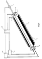
- Figure 1 shows a pipe liner section 2 of thermoplastic material placed in a pipeline 1 to be lined.
- the pipe liner section shown has an essentially C-shaped cross-section, while its original, undeformed shape is cylindrical.
- the method according to the invention can also be used for the installation of other pipe liners of thermoplastic material, such as pipes of which the diameter has been radially reduced.
- the two ends of the pipe liner section are shut off by shut-off elements 3, 4.
- a heating medium source 5 and a pressure medium source 6 are then connected to bores in the shut-off element 3.
- a control valve 7 is also connected to a bore in the shut-off element 4.
- temperature measuring elements 8, 9 are fitted on the inside and the outside respectively of the wall at an end of the pipe liner section 2 which just projects outside the pipeline 1, for example in a manhole or in an open trench.
- the signals from the temperature measuring elements 8, 9 are fed to a control device 10, which is connected to the heating medium source 5 and the pressure medium source 6.
- Other signals for example relating to the pressure in the Inside of the pipe liner section 2, can also be fed to the control device 10.
- the method for installing the pipe liner section 2 in a close fit against the inside of the pipeline 1 which it is still in its deformed C-shaped configuration is as follows:
- a heating and pressure medium for example steam
- a first pressure is exerted on the pipe liner section.
- the shape memory of the thermoplastic material of the pipe liner section assisted by the first pressure, causes the pipe liner section 2 to return virtually to its original, cylindrical cross-section.
- the rise in the temperature of the wall is determined by the temperature measuring elements 8, 9.
- the outside of the wall will usually have a lower temperature than the inside of the wall, because the outside of the wall is in contact with the cold environment.
- the signals from both temperature measuring elements 8, 9 are used for controlling the method.
- the supply of heat to the pipe liner section is put to a stop when the temperature measuring element 8 placed on the inside of the wall indicates approximately the value of the temperature of the heating medium and the temperature measuring element 9 on the outside of the wall indicates a virtually constant value.
- the second step of the method is then carried out, with the object of ensuring that the pipe liner section 2 comes to rest in a tight fit against the inside of the pipeline 1.
- a pressure medium for example compressed air
- the pipe liner section will gradually cool down by giving off heat to its environment.
- An additional cooling medium may be fed in if necessary.
- the second pressure causes a stress in the wall of the pipe liner section, as a result of which the latter is pressed against the pipeline.
- the admissible yield stress of the plastic material of the wall increases.
- the second pressure is gradually increased.
- the second pressure is regulated by control device 10 depending on a reference temperature of the wall determined by the temperature elements 8, 9.
- the reference temperature is the average of the temperatures of the outside and the inside of the wall. If on the basis of experience the decline of the temperature of the wall after ending of the supply of heat to the pipe liner section is approximately known, a control device which is time-dependent will suffice.
- the second pressure is regulated in such a way that it causes a stress in the wall of the pipe liner section which approximately corresponds to half the yield stress at the reference temperature of the wall of the pipe liner section.
- the diameter of the pipe liner section in the undeformed state can correspond to the inside diameter of the pipeline 1 to be lined, so that the pipe liner section comes to rest against the inside of the pipeline during the first step.
- the method described also makes it possible to install a pipe liner section in a close fit in a pipeline, the diameter of the pipe liner section in the undeformed state being slightly smaller than the inside diameter of the pipeline to be lined, in practice up to about 6% smaller.
- the second pressure exerted in the second step is then regulated in such a way that the diameter of the pipe liner section increases, so that it comes to rest in a close fit against the pipeline. In this way it is possible to accommodate variations in inside diameters of the pipelines to be lined, and a smaller range of pipe liner sections will suffice for lining the large number of sizes of pipelines.
- Figure 2 shows the curve of the second pressure in the case of the example which follows of the installation of a pipe liner section in the manner described in connection with Figure 1.
- the pipe liner section is made of high-density polyethylene (HDPE), and in the undeformed state has a diameter of 200 mm and a wall thickness of 12 mm.
- the crystalline melting temperature of the plastic material is about 130°C.
- the second pressure of 5.8 bar is the maximum pressure in the given circumstances. This maximum pressure depends partly on the wall thickness of the pipe liner section, and partly on the capabilities of the equipment used for the installation, while it was ultimately found that a further increase in the second pressure did not result in any appreciable increase in the diameter of the pipe liner section at these lower temperatures.
- the value of the second pressure is maintained until the second pressure is relieved completely when a temperature of about 30°C is reached.
- the stress caused in the wall of the pipe liner section by the second pressure mentioned in this example at the highest reference temperature is slightly greater than half the yield stress admissible at that reference temperature, while the stress at the lower reference temperatures lies slightly below this value.
- the diameter of the pipe liner section is measured at a place where it is projecting out of the pipeline, for example in a gulley or in an open trench. It is then possible to relate the second pressure in the pipe liner section to the measured diameter during the second step and to regulate it in such a way that a continuous increase in the diameter is obtained until the desired final diameter is achieved.
- the control can be automated by linking the diameter measuring means to the control device 10.
Landscapes
- Engineering & Computer Science (AREA)
- General Engineering & Computer Science (AREA)
- Manufacturing & Machinery (AREA)
- Mechanical Engineering (AREA)
- Lining Or Joining Of Plastics Or The Like (AREA)
- Application Of Or Painting With Fluid Materials (AREA)
Abstract
Description
- The present invention relates to a method for lining a pipeline, in particular a sewer, by means of a deformed pipe liner section with a wall made of thermoplastic material, comprising inserting the pipe liner section into the pipeline, shutting off the pipe liner section at its ends, in a first step supplying a heating and pressure medium to the inside of the shut-off pipe liner section, for the purpose of supplying heat to the pipe liner section and exerting a first pressure on the pipe liner section, so that the latter comes to rest against the inside of the pipeline, and in a second step, after the wall of the pipe liner section has reached a predetermined temperature profile and the supply of heat has been put to a stop, supplying a pressure medium to the inside of the shut-off pipe liner section, for the purpose of exerting a second pressure on the pipe liner section, which second pressure is higher than the first pressure.
- Such a method is known from EP 0,301,697. In the case of the known method, in a first step heat is supplied by means of hot fluid to a previously deformed pipe liner section and a first pressure is exerted on the pipe liner section, so that the latter returns virtually to its original undeformed shape. Subsequently, in a second step the pressure on the pipe liner section is increased to a second pressure. This second pressure is maintained at a constant high value for a specific period. In this known process, in order to ensure that the pipe liner section comes to rest in a sufficiently tight fit against the inside of the pipeline, it is necessary to either work at very high pressures, which give rise to a large risk of tearing or cracking of the pipe liner section, and/or to use a close-fitting plug driven by cold water through the pipe liner section. This is a time-consuming method.
- The object of the invention is to provide an improved method according to the preamble which results in a much lower risk of cracks in the pipe liner section and allows an excellent tight fit of the lines, and is characterized in that the second pressure is gradually increased. This ensures that the stress produced in the wall of the pipe liner section by the second pressure has a trend similar to the increasing admissible yield stress in the wall of the pipe liner section at the falling temperature of the pipe liner section during this second step. In this way it is ensured that the pipe liner section lies in a tight fit against the inside of the pipeline. This also makes it possible to increase the diameter of the pipe liner section during the installation in such a way that pipelines with a wide variation of internal diameters can be lined with a pipe liner section of one specific size, so that a smaller range of pipe liner sections will suffice.
- The second pressure is preferably regulated depending on the yield stress in the wall of the pipe liner section which is admissible at a reference temperature of the wall of the pipe liner section.
- In an advantageous embodiment of the method, the second pressure is regulated depending on the measured diameter of a part of the pipe liner section not lying inside the pipeline. The second pressure is preferably regulated in such a way here that a constant increase in diameter occurs until a predetermined value is reached.
- In another embodiment, the second pressure is regulated depending on time. Such a method will be possible in particular if on the basis of experience the curve of the temperature drop in the second step is approximately known, so that no reference temperature of the wall need be determined.
- The second pressure advantageously causes a stress in the wall of the pipe liner section that approximately corresponds to half the yield stress at a reference temperature of the wall of the pipe liner section.
- The temperature profile of the wall of the pipe liner section is preferably determined by measuring the temperature of the outside of the wall and of the inside of the wall.
- The reference temperature of the wall of the pipe liner section is also preferably determined by measuring the temperature of the outside of the wall and of the inside of the wall, and then determining the average value of the two temperatures.
- It is advantageous here for the temperature of the inside of the wall to be measured at a point situated at a distance from the point where the heating and pressure medium is supplied.
- The method according to the invention will be explained below with reference to the drawing, in which:
- Fig. 1 shows a diagrammatic view of the installation of a deformed pipe liner section in a pipeline; and
- Fig. 2 shows an example of the curve of the second pressure in the case of the method according to the invention.
- Figure 1 shows a
pipe liner section 2 of thermoplastic material placed in apipeline 1 to be lined. In the deformed configuration the pipe liner section shown has an essentially C-shaped cross-section, while its original, undeformed shape is cylindrical. However, the method according to the invention can also be used for the installation of other pipe liners of thermoplastic material, such as pipes of which the diameter has been radially reduced. After thepipe liner section 2 has been drawn into thepipeline 1 by suitable means, the two ends of the pipe liner section are shut off by shut-offelements heating medium source 5 and apressure medium source 6 are then connected to bores in the shut-offelement 3. A control valve 7 is also connected to a bore in the shut-offelement 4. For determining the temperature profile of the wall of thepipe liner section 2,temperature measuring elements 8, 9 are fitted on the inside and the outside respectively of the wall at an end of thepipe liner section 2 which just projects outside thepipeline 1, for example in a manhole or in an open trench. The signals from thetemperature measuring elements 8, 9 are fed to acontrol device 10, which is connected to theheating medium source 5 and thepressure medium source 6. Other signals, for example relating to the pressure in the Inside of thepipe liner section 2, can also be fed to thecontrol device 10. The method for installing thepipe liner section 2 in a close fit against the inside of thepipeline 1 which it is still in its deformed C-shaped configuration is as follows: In a first step, a heating and pressure medium, for example steam, is fed from theheating medium source 5 to the inside of thepipe liner section 2. This causes the temperature of the wall of the pipe liner section to rise, and a first pressure is exerted on the pipe liner section. As a result of the rise in the temperature of the wall, the shape memory of the thermoplastic material of the pipe liner section, assisted by the first pressure, causes thepipe liner section 2 to return virtually to its original, cylindrical cross-section. The rise in the temperature of the wall is determined by thetemperature measuring elements 8, 9. In this case the outside of the wall will usually have a lower temperature than the inside of the wall, because the outside of the wall is in contact with the cold environment. The signals from bothtemperature measuring elements 8, 9 are used for controlling the method. The supply of heat to the pipe liner section is put to a stop when thetemperature measuring element 8 placed on the inside of the wall indicates approximately the value of the temperature of the heating medium and the temperature measuring element 9 on the outside of the wall indicates a virtually constant value. The second step of the method is then carried out, with the object of ensuring that thepipe liner section 2 comes to rest in a tight fit against the inside of thepipeline 1. For this purpose, a pressure medium, for example compressed air, is fed from thepressure medium source 6 to the inside of thepipe liner section 2, as a result of which a second pressure is exerted on the pipe liner section. The pipe liner section will gradually cool down by giving off heat to its environment. An additional cooling medium may be fed in if necessary. The second pressure causes a stress in the wall of the pipe liner section, as a result of which the latter is pressed against the pipeline. When the temperature of the wall of thepipe liner 2 section drops, the admissible yield stress of the plastic material of the wall increases. In order to ensure that the second pressure exerted on the pipe liner section continues to press the wall of the pipe liner section forcefully against the pipeline, the second pressure is gradually increased. In the case of the arrangement shown, the second pressure is regulated bycontrol device 10 depending on a reference temperature of the wall determined by thetemperature elements 8, 9. In this case the reference temperature is the average of the temperatures of the outside and the inside of the wall. If on the basis of experience the decline of the temperature of the wall after ending of the supply of heat to the pipe liner section is approximately known, a control device which is time-dependent will suffice. In the second step the second pressure is regulated in such a way that it causes a stress in the wall of the pipe liner section which approximately corresponds to half the yield stress at the reference temperature of the wall of the pipe liner section. - In the case of the method according to the invention, the diameter of the pipe liner section in the undeformed state can correspond to the inside diameter of the
pipeline 1 to be lined, so that the pipe liner section comes to rest against the inside of the pipeline during the first step. The method described also makes it possible to install a pipe liner section in a close fit in a pipeline, the diameter of the pipe liner section in the undeformed state being slightly smaller than the inside diameter of the pipeline to be lined, in practice up to about 6% smaller. When such a pipe liner section is being installed it does not yet lie against the inside of the pipeline after the first step. The second pressure exerted in the second step is then regulated in such a way that the diameter of the pipe liner section increases, so that it comes to rest in a close fit against the pipeline. In this way it is possible to accommodate variations in inside diameters of the pipelines to be lined, and a smaller range of pipe liner sections will suffice for lining the large number of sizes of pipelines. - Figure 2 shows the curve of the second pressure in the case of the example which follows of the installation of a pipe liner section in the manner described in connection with Figure 1. The pipe liner section is made of high-density polyethylene (HDPE), and in the undeformed state has a diameter of 200 mm and a wall thickness of 12 mm. The crystalline melting temperature of the plastic material is about 130°C. After the pipe liner section has been drawn into the pipeline and the ends of the pipe liner section have been shut off, in a first step steam at a temperature of 126 - 127°C and a pressure of 1.4 - 1.45 bar is fed in. This causes the pipe liner section quickly to assume its original cylindrical shape. The supply of steam is continued until the temperature of the inside of the wall is 125°C and the temperature of the outside of the wall is 85°C. It is pointed out here that the temperature of the outside of the wall ultimately reaches a virtually constant value through heat loss to the cold environment. If the wall has reached the abovementioned temperature profile, the supply of steam is put to a stop and in a second step a second pressure is exerted immediately on the pipe liner section by means of compressed air. According to the invention, the second pressure is gradually increased. This is carried out here depending on the reference temperature determined by the temperature measuring elements, which temperature is the average of the temperature of the inside and the outside of the wall, and depending on the yield stress in the wall of the pipe liner section which is admissible at that reference temperature. In this case the table below is used in this example.
Reference temperature (°C) Second pressure (bar) 106 3.1 96 3.5 87 4.1 80 4.7 70 5.2 60 5.8 - The second pressure of 5.8 bar is the maximum pressure in the given circumstances. This maximum pressure depends partly on the wall thickness of the pipe liner section, and partly on the capabilities of the equipment used for the installation, while it was ultimately found that a further increase in the second pressure did not result in any appreciable increase in the diameter of the pipe liner section at these lower temperatures. When the temperature of the wall falls further, the value of the second pressure is maintained until the second pressure is relieved completely when a temperature of about 30°C is reached. The stress caused in the wall of the pipe liner section by the second pressure mentioned in this example at the highest reference temperature is slightly greater than half the yield stress admissible at that reference temperature, while the stress at the lower reference temperatures lies slightly below this value.
- In an advantageous embodiment of the method, after the first step the diameter of the pipe liner section is measured at a place where it is projecting out of the pipeline, for example in a gulley or in an open trench. It is then possible to relate the second pressure in the pipe liner section to the measured diameter during the second step and to regulate it in such a way that a continuous increase in the diameter is obtained until the desired final diameter is achieved. The control can be automated by linking the diameter measuring means to the
control device 10.
Claims (8)
- Method for lining a pipeline, in particular a sewer, by means of a deformed pipe liner section with a wall made of thermoplastic material, comprising inserting of the pipe liner section into the pipeline, shutting off the pipe liner section at its ends, in a first step supplying a heating and pressure medium to the inside of the shut-off pipe liner section, for the purpose of supplying heat to the pipe liner section and exerting a first pressure on the pipe liner section, so that the latter comes to rest against the inside of the pipeline, and in a second step, after the wall of the pipe liner section has reached a predetermined temperature profile and the supply of heat has ended, supplying a pressure medium to the inside of the shut-off pipe liner section, for the purpose of exerting a second pressure on the pipe liner section, which second pressure is higher than the first pressure, characterized in that the second pressure is gradually increased.
- Method according to claim 1, characterized in that the second pressure is regulated depending on the yield stress in the wall of the pipe liner section which is admissible at a reference temperature of the wall of the pipe liner section.
- Method according to claim 1, characterized in that the second pressure is regulated depending on the measured diameter of a part of the pipe liner section not lying inside the pipeline to be lined.
- Method according to claim 1, characterized in that the second pressure is regulated depending on time.
- Method according to one of the preceding claims, characterized in that the second pressure causes a stress in the wall of the pipe liner section that approximately corresponds to half the yield stress at a reference temperature of the wall of the pipe liner section.
- Method according to one of the preceding claims, characterized in that the temperature profile of the wall of the pipe liner section is determined by measuring the temperature of the outside of the wall and of the inside of the wall.
- Method according to one of the preceding claims, characterized in that the reference temperature of the wall of the pipe liner section is determined by measuring the temperature of the outside of the wall and of the inside of the wall, and then determining the average value of the two temperatures.
- Method according to claim 6 or 7, characterized in that the temperature of the inside of the wall is measured at a point situated at a distance from the point where the heating and pressure medium is supplied.
Applications Claiming Priority (3)
| Application Number | Priority Date | Filing Date | Title |
|---|---|---|---|
| NL9202030A NL9202030A (en) | 1992-11-23 | 1992-11-23 | Method for internally lining a pipeline, in particular a sewer pipe. |
| NL9202030 | 1992-11-23 | ||
| PCT/NL1993/000242 WO1994012336A1 (en) | 1992-11-23 | 1993-11-16 | Method for lining a pipeline, in particular a sewer |
Publications (2)
| Publication Number | Publication Date |
|---|---|
| EP0669867A1 EP0669867A1 (en) | 1995-09-06 |
| EP0669867B1 true EP0669867B1 (en) | 1997-02-19 |
Family
ID=19861548
Family Applications (1)
| Application Number | Title | Priority Date | Filing Date |
|---|---|---|---|
| EP94902126A Expired - Lifetime EP0669867B1 (en) | 1992-11-23 | 1993-11-16 | Method for lining a pipeline, in particular a sewer |
Country Status (8)
| Country | Link |
|---|---|
| EP (1) | EP0669867B1 (en) |
| AT (1) | ATE149013T1 (en) |
| AU (1) | AU5660194A (en) |
| DE (1) | DE69308218T2 (en) |
| DK (1) | DK0669867T3 (en) |
| ES (1) | ES2100671T3 (en) |
| NL (1) | NL9202030A (en) |
| WO (1) | WO1994012336A1 (en) |
Cited By (1)
| Publication number | Priority date | Publication date | Assignee | Title |
|---|---|---|---|---|
| WO2025218845A1 (en) * | 2024-04-16 | 2025-10-23 | Relineeurope Gmbh | Method for refurbishing shafts |
Families Citing this family (1)
| Publication number | Priority date | Publication date | Assignee | Title |
|---|---|---|---|---|
| US7104574B2 (en) | 2000-01-20 | 2006-09-12 | Uponor Eti Company | Corrugated pipe connection joint |
Family Cites Families (1)
| Publication number | Priority date | Publication date | Assignee | Title |
|---|---|---|---|---|
| ES2054808T5 (en) * | 1987-07-27 | 1999-12-16 | Pipe Liners Inc | A METHOD AND APPARATUS FOR THE PRODUCTION OF A DEFORMED TUBULAR CROSS SECTION TUBE. |
-
1992
- 1992-11-23 NL NL9202030A patent/NL9202030A/en not_active Application Discontinuation
-
1993
- 1993-11-16 AT AT94902126T patent/ATE149013T1/en active
- 1993-11-16 DE DE69308218T patent/DE69308218T2/en not_active Expired - Lifetime
- 1993-11-16 WO PCT/NL1993/000242 patent/WO1994012336A1/en not_active Ceased
- 1993-11-16 DK DK94902126.5T patent/DK0669867T3/en active
- 1993-11-16 AU AU56601/94A patent/AU5660194A/en not_active Abandoned
- 1993-11-16 ES ES94902126T patent/ES2100671T3/en not_active Expired - Lifetime
- 1993-11-16 EP EP94902126A patent/EP0669867B1/en not_active Expired - Lifetime
Cited By (1)
| Publication number | Priority date | Publication date | Assignee | Title |
|---|---|---|---|---|
| WO2025218845A1 (en) * | 2024-04-16 | 2025-10-23 | Relineeurope Gmbh | Method for refurbishing shafts |
Also Published As
| Publication number | Publication date |
|---|---|
| WO1994012336A1 (en) | 1994-06-09 |
| DK0669867T3 (en) | 1997-03-10 |
| DE69308218T2 (en) | 1997-06-19 |
| ES2100671T3 (en) | 1997-06-16 |
| EP0669867A1 (en) | 1995-09-06 |
| DE69308218D1 (en) | 1997-03-27 |
| ATE149013T1 (en) | 1997-03-15 |
| NL9202030A (en) | 1994-06-16 |
| AU5660194A (en) | 1994-06-22 |
Similar Documents
| Publication | Publication Date | Title |
|---|---|---|
| US6982051B2 (en) | Fusion process for conduit | |
| EP0120277A1 (en) | Compression sleeve for a tube repair | |
| US20020024220A1 (en) | Bendable polymer-lined water heater connector | |
| CA1325584C (en) | Method and apparatus for the lining of existing pipes | |
| EP0848659B1 (en) | Pipe liner and method of installation | |
| US9086184B2 (en) | System and method for conduit reparation | |
| EP0669867A1 (en) | Method for lining a pipeline, in particular a sewer. | |
| AU2004250150B2 (en) | Bladder system for conduit expansion | |
| JP3190688B2 (en) | Pipe lining | |
| US2641491A (en) | Replacement t or fitting | |
| EP0574488B1 (en) | Method for fitting an inner tube in an existing pipeline using air venting means, and pipeline with inner tube of thermoplastics | |
| US4828767A (en) | Method and system for installing steam desuperheaters | |
| EP0537239B1 (en) | Method and installation for fitting an inner tube in an existing pipeline | |
| CN208153896U (en) | A kind of slide-in self-anchored type socket joint connection structure | |
| EP4227569B1 (en) | Method of lining branch area in pipeline | |
| JPH1089516A (en) | Valve for plastic pipeline | |
| CN2491487Y (en) | Expansion compensator | |
| US5863569A (en) | Apparatus for forming bellings on thermoplastic pipes | |
| AU2013242782B2 (en) | System and arrangement for conduit reparation | |
| WO2004113625A2 (en) | System and arrangement for conduit reparation | |
| EP0660909A1 (en) | Method and apparatus for fitting an inner tube in an existing pipeline while continuously supplying heat, and a pipeline obtained in this way | |
| AU6654096A (en) | Pipe liner and method of installation | |
| HK1015163A1 (en) | Method for lining a pipe with a polymer liner | |
| HK1015163B (en) | Method for lining a pipe with a polymer liner | |
| CN104534198A (en) | Rupture repairing method for short pipe of graphite column |
Legal Events
| Date | Code | Title | Description |
|---|---|---|---|
| PUAI | Public reference made under article 153(3) epc to a published international application that has entered the european phase |
Free format text: ORIGINAL CODE: 0009012 |
|
| 17P | Request for examination filed |
Effective date: 19950117 |
|
| AK | Designated contracting states |
Kind code of ref document: A1 Designated state(s): AT BE CH DE DK ES FR GB GR IE IT LI LU MC NL PT SE |
|
| GRAG | Despatch of communication of intention to grant |
Free format text: ORIGINAL CODE: EPIDOS AGRA |
|
| 17Q | First examination report despatched |
Effective date: 19960506 |
|
| GRAH | Despatch of communication of intention to grant a patent |
Free format text: ORIGINAL CODE: EPIDOS IGRA |
|
| GRAH | Despatch of communication of intention to grant a patent |
Free format text: ORIGINAL CODE: EPIDOS IGRA |
|
| ITF | It: translation for a ep patent filed | ||
| GRAA | (expected) grant |
Free format text: ORIGINAL CODE: 0009210 |
|
| AK | Designated contracting states |
Kind code of ref document: B1 Designated state(s): AT BE CH DE DK ES FR GB GR IE IT LI LU MC NL PT SE |
|
| PG25 | Lapsed in a contracting state [announced via postgrant information from national office to epo] |
Ref country code: GR Free format text: LAPSE BECAUSE OF FAILURE TO SUBMIT A TRANSLATION OF THE DESCRIPTION OR TO PAY THE FEE WITHIN THE PRESCRIBED TIME-LIMIT Effective date: 19970219 Ref country code: BE Effective date: 19970219 |
|
| REF | Corresponds to: |
Ref document number: 149013 Country of ref document: AT Date of ref document: 19970315 Kind code of ref document: T |
|
| REG | Reference to a national code |
Ref country code: CH Ref legal event code: NV Representative=s name: TROESCH SCHEIDEGGER WERNER AG Ref country code: CH Ref legal event code: EP |
|
| REG | Reference to a national code |
Ref country code: DK Ref legal event code: T3 |
|
| REF | Corresponds to: |
Ref document number: 69308218 Country of ref document: DE Date of ref document: 19970327 |
|
| ET | Fr: translation filed | ||
| REG | Reference to a national code |
Ref country code: IE Ref legal event code: FG4D Free format text: 72127 |
|
| PG25 | Lapsed in a contracting state [announced via postgrant information from national office to epo] |
Ref country code: PT Effective date: 19970519 |
|
| REG | Reference to a national code |
Ref country code: ES Ref legal event code: FG2A Ref document number: 2100671 Country of ref document: ES Kind code of ref document: T3 |
|
| PG25 | Lapsed in a contracting state [announced via postgrant information from national office to epo] |
Ref country code: LU Free format text: LAPSE BECAUSE OF NON-PAYMENT OF DUE FEES Effective date: 19971116 Ref country code: IE Free format text: LAPSE BECAUSE OF NON-PAYMENT OF DUE FEES Effective date: 19971116 |
|
| PLBE | No opposition filed within time limit |
Free format text: ORIGINAL CODE: 0009261 |
|
| STAA | Information on the status of an ep patent application or granted ep patent |
Free format text: STATUS: NO OPPOSITION FILED WITHIN TIME LIMIT |
|
| 26N | No opposition filed | ||
| PG25 | Lapsed in a contracting state [announced via postgrant information from national office to epo] |
Ref country code: MC Free format text: LAPSE BECAUSE OF NON-PAYMENT OF DUE FEES Effective date: 19980531 |
|
| PGFP | Annual fee paid to national office [announced via postgrant information from national office to epo] |
Ref country code: DK Payment date: 19981013 Year of fee payment: 6 |
|
| PGFP | Annual fee paid to national office [announced via postgrant information from national office to epo] |
Ref country code: NL Payment date: 19981130 Year of fee payment: 6 |
|
| PG25 | Lapsed in a contracting state [announced via postgrant information from national office to epo] |
Ref country code: DK Free format text: LAPSE BECAUSE OF NON-PAYMENT OF DUE FEES Effective date: 19991116 |
|
| PG25 | Lapsed in a contracting state [announced via postgrant information from national office to epo] |
Ref country code: NL Free format text: LAPSE BECAUSE OF NON-PAYMENT OF DUE FEES Effective date: 20000601 |
|
| NLV4 | Nl: lapsed or anulled due to non-payment of the annual fee |
Effective date: 20000601 |
|
| REG | Reference to a national code |
Ref country code: DK Ref legal event code: EBP |
|
| REG | Reference to a national code |
Ref country code: GB Ref legal event code: IF02 |
|
| PGFP | Annual fee paid to national office [announced via postgrant information from national office to epo] |
Ref country code: SE Payment date: 20061129 Year of fee payment: 14 Ref country code: CH Payment date: 20061129 Year of fee payment: 14 |
|
| EUG | Se: european patent has lapsed | ||
| PG25 | Lapsed in a contracting state [announced via postgrant information from national office to epo] |
Ref country code: LI Free format text: LAPSE BECAUSE OF NON-PAYMENT OF DUE FEES Effective date: 20071130 Ref country code: CH Free format text: LAPSE BECAUSE OF NON-PAYMENT OF DUE FEES Effective date: 20071130 |
|
| REG | Reference to a national code |
Ref country code: CH Ref legal event code: PL |
|
| PG25 | Lapsed in a contracting state [announced via postgrant information from national office to epo] |
Ref country code: SE Free format text: LAPSE BECAUSE OF NON-PAYMENT OF DUE FEES Effective date: 20071117 |
|
| PGFP | Annual fee paid to national office [announced via postgrant information from national office to epo] |
Ref country code: FR Payment date: 20081127 Year of fee payment: 16 |
|
| PGFP | Annual fee paid to national office [announced via postgrant information from national office to epo] |
Ref country code: GB Payment date: 20081128 Year of fee payment: 16 |
|
| GBPC | Gb: european patent ceased through non-payment of renewal fee |
Effective date: 20091116 |
|
| REG | Reference to a national code |
Ref country code: FR Ref legal event code: ST Effective date: 20100730 |
|
| PG25 | Lapsed in a contracting state [announced via postgrant information from national office to epo] |
Ref country code: FR Free format text: LAPSE BECAUSE OF NON-PAYMENT OF DUE FEES Effective date: 20091130 |
|
| PG25 | Lapsed in a contracting state [announced via postgrant information from national office to epo] |
Ref country code: GB Free format text: LAPSE BECAUSE OF NON-PAYMENT OF DUE FEES Effective date: 20091116 |
|
| PGFP | Annual fee paid to national office [announced via postgrant information from national office to epo] |
Ref country code: DE Payment date: 20121114 Year of fee payment: 20 |
|
| PGFP | Annual fee paid to national office [announced via postgrant information from national office to epo] |
Ref country code: ES Payment date: 20121127 Year of fee payment: 20 Ref country code: IT Payment date: 20121116 Year of fee payment: 20 |
|
| PGFP | Annual fee paid to national office [announced via postgrant information from national office to epo] |
Ref country code: AT Payment date: 20121126 Year of fee payment: 20 |
|
| REG | Reference to a national code |
Ref country code: DE Ref legal event code: R071 Ref document number: 69308218 Country of ref document: DE |
|
| REG | Reference to a national code |
Ref country code: AT Ref legal event code: MK07 Ref document number: 149013 Country of ref document: AT Kind code of ref document: T Effective date: 20131116 |
|
| PG25 | Lapsed in a contracting state [announced via postgrant information from national office to epo] |
Ref country code: DE Free format text: LAPSE BECAUSE OF EXPIRATION OF PROTECTION Effective date: 20131119 |
|
| REG | Reference to a national code |
Ref country code: ES Ref legal event code: FD2A Effective date: 20140131 |
|
| PG25 | Lapsed in a contracting state [announced via postgrant information from national office to epo] |
Ref country code: ES Free format text: LAPSE BECAUSE OF EXPIRATION OF PROTECTION Effective date: 20131117 |