EP0668963B1 - Fault diagnosis method for injectors of internal combustion engine high-pressure injection systems - Google Patents
Fault diagnosis method for injectors of internal combustion engine high-pressure injection systems Download PDFInfo
- Publication number
- EP0668963B1 EP0668963B1 EP94927542A EP94927542A EP0668963B1 EP 0668963 B1 EP0668963 B1 EP 0668963B1 EP 94927542 A EP94927542 A EP 94927542A EP 94927542 A EP94927542 A EP 94927542A EP 0668963 B1 EP0668963 B1 EP 0668963B1
- Authority
- EP
- European Patent Office
- Prior art keywords
- coil
- determining
- short
- capacitor
- charge
- Prior art date
- Legal status (The legal status is an assumption and is not a legal conclusion. Google has not performed a legal analysis and makes no representation as to the accuracy of the status listed.)
- Expired - Lifetime
Links
- 238000000034 method Methods 0.000 title claims abstract description 21
- 238000003745 diagnosis Methods 0.000 title claims description 6
- 238000002347 injection Methods 0.000 title claims description 6
- 239000007924 injection Substances 0.000 title claims description 6
- 238000002485 combustion reaction Methods 0.000 title claims description 5
- 239000003990 capacitor Substances 0.000 claims abstract description 31
- 238000007599 discharging Methods 0.000 claims abstract 4
- 238000012360 testing method Methods 0.000 abstract description 6
- 238000010586 diagram Methods 0.000 description 2
- 230000004075 alteration Effects 0.000 description 1
- 231100001261 hazardous Toxicity 0.000 description 1
Images


Classifications
-
- F—MECHANICAL ENGINEERING; LIGHTING; HEATING; WEAPONS; BLASTING
- F02—COMBUSTION ENGINES; HOT-GAS OR COMBUSTION-PRODUCT ENGINE PLANTS
- F02D—CONTROLLING COMBUSTION ENGINES
- F02D41/00—Electrical control of supply of combustible mixture or its constituents
- F02D41/20—Output circuits, e.g. for controlling currents in command coils
-
- F—MECHANICAL ENGINEERING; LIGHTING; HEATING; WEAPONS; BLASTING
- F02—COMBUSTION ENGINES; HOT-GAS OR COMBUSTION-PRODUCT ENGINE PLANTS
- F02D—CONTROLLING COMBUSTION ENGINES
- F02D41/00—Electrical control of supply of combustible mixture or its constituents
- F02D41/22—Safety or indicating devices for abnormal conditions
- F02D41/221—Safety or indicating devices for abnormal conditions relating to the failure of actuators or electrically driven elements
-
- F—MECHANICAL ENGINEERING; LIGHTING; HEATING; WEAPONS; BLASTING
- F02—COMBUSTION ENGINES; HOT-GAS OR COMBUSTION-PRODUCT ENGINE PLANTS
- F02D—CONTROLLING COMBUSTION ENGINES
- F02D41/00—Electrical control of supply of combustible mixture or its constituents
- F02D41/20—Output circuits, e.g. for controlling currents in command coils
- F02D2041/2003—Output circuits, e.g. for controlling currents in command coils using means for creating a boost voltage, i.e. generation or use of a voltage higher than the battery voltage, e.g. to speed up injector opening
- F02D2041/2006—Output circuits, e.g. for controlling currents in command coils using means for creating a boost voltage, i.e. generation or use of a voltage higher than the battery voltage, e.g. to speed up injector opening by using a boost capacitor
-
- F—MECHANICAL ENGINEERING; LIGHTING; HEATING; WEAPONS; BLASTING
- F02—COMBUSTION ENGINES; HOT-GAS OR COMBUSTION-PRODUCT ENGINE PLANTS
- F02D—CONTROLLING COMBUSTION ENGINES
- F02D41/00—Electrical control of supply of combustible mixture or its constituents
- F02D41/20—Output circuits, e.g. for controlling currents in command coils
- F02D2041/202—Output circuits, e.g. for controlling currents in command coils characterised by the control of the circuit
- F02D2041/2031—Control of the current by means of delays or monostable multivibrators
-
- F—MECHANICAL ENGINEERING; LIGHTING; HEATING; WEAPONS; BLASTING
- F02—COMBUSTION ENGINES; HOT-GAS OR COMBUSTION-PRODUCT ENGINE PLANTS
- F02D—CONTROLLING COMBUSTION ENGINES
- F02D41/00—Electrical control of supply of combustible mixture or its constituents
- F02D41/20—Output circuits, e.g. for controlling currents in command coils
- F02D2041/2068—Output circuits, e.g. for controlling currents in command coils characterised by the circuit design or special circuit elements
- F02D2041/2075—Type of transistors or particular use thereof
-
- F—MECHANICAL ENGINEERING; LIGHTING; HEATING; WEAPONS; BLASTING
- F02—COMBUSTION ENGINES; HOT-GAS OR COMBUSTION-PRODUCT ENGINE PLANTS
- F02D—CONTROLLING COMBUSTION ENGINES
- F02D41/00—Electrical control of supply of combustible mixture or its constituents
- F02D41/20—Output circuits, e.g. for controlling currents in command coils
- F02D2041/2086—Output circuits, e.g. for controlling currents in command coils with means for detecting circuit failures
- F02D2041/2089—Output circuits, e.g. for controlling currents in command coils with means for detecting circuit failures detecting open circuits
-
- F—MECHANICAL ENGINEERING; LIGHTING; HEATING; WEAPONS; BLASTING
- F02—COMBUSTION ENGINES; HOT-GAS OR COMBUSTION-PRODUCT ENGINE PLANTS
- F02D—CONTROLLING COMBUSTION ENGINES
- F02D41/00—Electrical control of supply of combustible mixture or its constituents
- F02D41/20—Output circuits, e.g. for controlling currents in command coils
- F02D2041/2086—Output circuits, e.g. for controlling currents in command coils with means for detecting circuit failures
- F02D2041/2093—Output circuits, e.g. for controlling currents in command coils with means for detecting circuit failures detecting short circuits
-
- Y—GENERAL TAGGING OF NEW TECHNOLOGICAL DEVELOPMENTS; GENERAL TAGGING OF CROSS-SECTIONAL TECHNOLOGIES SPANNING OVER SEVERAL SECTIONS OF THE IPC; TECHNICAL SUBJECTS COVERED BY FORMER USPC CROSS-REFERENCE ART COLLECTIONS [XRACs] AND DIGESTS
- Y02—TECHNOLOGIES OR APPLICATIONS FOR MITIGATION OR ADAPTATION AGAINST CLIMATE CHANGE
- Y02T—CLIMATE CHANGE MITIGATION TECHNOLOGIES RELATED TO TRANSPORTATION
- Y02T10/00—Road transport of goods or passengers
- Y02T10/10—Internal combustion engine [ICE] based vehicles
- Y02T10/40—Engine management systems
Definitions
- the present invention relates to a fault diagnosis method for the injectors of internal combustion engine high-pressure injection systems, in particular for detecting short-circuiting or open circuits on the injector coils.
- high-pressure injection systems comprise a number of injectors, opening and closing of which are controlled by means of a respective coil and a control circuit. Any short-circuiting or open circuits on the coil must therefore be detected immediately to ensure correct operation of the injector and also prevent damage to the injector control circuit. This applies in particular to short-circuiting of the injector, which, if not detected inmediately, may result in such high currents as to irreparably damage the electronic components of the control circuit.
- the EP-A-249 448 shows a fault diagnosis method for a coil.
- a short or open circuit of a coil is detected by charging the coil and then discharching it into a capacitor.
- the charge of the capacitor is then compared by comparing the surge voltage with a reference value.
- Figure 1 shows a simplified diagram of the circuit 1 for controlling a number of injectors.
- Circuit 1 comprises a number of actuator circuits M 1 , M 2 , ... connected parallel to one another between a supply line 4 and a ground line 5, and each comprising, in series, a coil L 1 , L 2 , ... for controlling a respective injector, a twisted cable C 1 , C 2 , ... of appropriate length, and a controlled switch S 1 , S 2 , ... .
- a voltage source 7 is also connected, via a decoupling diode 8, between supply line 4 and ground line 5.
- the common node N 1 , N 2, ... between each coil L 1 , L 2 , ... and each controlled switch S 1 , S 2 ... is connected to a terminal 11 of a storage or tank capacitor 12 via a respective decoupling diode D 1 , D 2 , ... with its cathode connected to terminal 11; and terminal 11 is connected to supply line 4 via a controlled switch 14.
- the method according to the present invention is performed during startup, as soon as the ignition key is turned, to prevent the engine from being started up in the event of a fault which may impair operation or even cause irreparable damage to the component parts of control circuit 1.
- the method consists in briefly and successively turning on the controlled switches of the coils to connect the switches successively to the battery.
- the current through the supplied actuator circuit is low (due to the short connection time), and is high in the event of short-circuiting of the coil.
- the controlled switch is turned off, the current from the previously supplied actuator circuit is transferred to storage capacitor 12 which therefore charges to a voltage depending on the amount of current transferred, which in turn is related to the current through the previously supplied actuator circuit.
- the capacitor charges to a much higher voltage as compared with a properly connected coil, so that short-circuiting may be detected by calculating the voltage increase of the capacitor and comparing it with a threshold value.
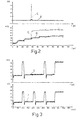
- Figure 2 shows a graph of the current through the injector circuit and a corresponding graph of the capacitor voltage in the event of correct connection (curves A, B) and short-circuiting (curves C, D) of the coil.
- Figure 3 shows graphs of the voltage of storage capacitor 12 in the event of an open circuit on a coil (curve E) and correct connection of all the coils (curve F relative to a different supply voltage value).
- curve E the voltage of storage capacitor 12 in the event of an open circuit on a coil
- curve F correct connection of all the coils
- storage capacitor 12 is discharged after each coil is tested, for better indicating, each time, the charge of the capacitor, the final value of which depends on various parameters, including the initial voltage prior to current transfer.
- block 20 measures the voltage V(0) of capacitor 12; block 21 sets an injector counter i to 1; and block 22 closes switch S i for a very short time T1, e.g. from 3 to 30 ⁇ s, which time must be long enough to permit current flow, but short enough to prevent damaging the controlled switch in the event of short-circuiting (in which case, the current may reach a few tens of Amps).
- T1 very short time
- the method described therefore provides for indicating any faults without damaging the control circuit, by first performing the short-circuit test indicating the more hazardous condition and which, by virtue of the very short length of time the switches are closed, poses no risk to the circuit, and by subsequently performing the open-circuit test which may thus be performed in the most appropriate manner by closing the controlled switches for a greater length of time to allow a greater current flow and so indicate any open circuits with no danger of damaging the circuit.
- the method according to the present invention is straightforward and reliable, and may be program implemented with no complex, high-cost alterations to the circuitry.
Landscapes
- Engineering & Computer Science (AREA)
- Chemical & Material Sciences (AREA)
- Combustion & Propulsion (AREA)
- Mechanical Engineering (AREA)
- General Engineering & Computer Science (AREA)
- Electrical Control Of Air Or Fuel Supplied To Internal-Combustion Engine (AREA)
- Combined Controls Of Internal Combustion Engines (AREA)
Abstract
Description
Claims (8)
- A fault diagnosis method for the injectors of internal combustion engine high-pressure injection systems, comprises the steps of: supplying an injector coil (L1, L2) for a predetermined time; discharging said coil into a storage capacitor (12); measuring the charge of said storage capacitor; and comparing said charge with a predetermined threshold said step of measuring said charge comprises the step of determining the voltage increase of said storage capacitor (12) as said coil (L1, 12) is discharged, characterized in that, to determine short-circuiting of said injector coil (L1, L2), said step of determining said voltage increase comprises the step of memorizing the charge value of said capacitor (12) immediately prior to said step of supplying said coil; measuring the voltage of said capacitor after said charging step; and determining the difference between said memorized charge value and said measured voltage.
- A fault diagnosis method for the injectors of internal combustion engine high-pressure injection systems, comprises the steps of: supplying an injector coil (L1, L2) for a predetermined time; discharging said coil into a storage capacitor (12); measuring the charge of said storage capacitor; and comparing said charge with a predetermined threshold said step of measuring said charge comprises the step of determining the voltage increase of said storage capacitor (12) as said coil (L1, 12) is discharged, characterized in that, to determine the presence of open circuits of said injector coil (L1, L2), said step of determining said voltage increase comprises the step of discharging said capacitor (12) immediately prior to said step of supplying said coil; memorizing the discharge value of said capacitor; measuring the voltage of said capacitor after said charging step; and determining the difference between said memorized discharge value and said measured voltage.
- A method as claimed in Claim 1, characterized in that it comprises the step of determining short-circuiting of said injector coil (L1, L2) and wherein said coil is supplied for a first very short time interval (T1)
- A method as claimed in Claim 3, characterized in that said first time interval ranges from 3 to 30 µs.
- A method as claimed in Claim 3 or 4, characterized in that said step of determining short-circuiting of said injector coil (L1, L2) is followed by the step of determining the presence of open -circuits and wherein said coil is supplied for a second time interval (T2) greater than said first time interval (T1).
- A method as claimed in Claim 5, characterized in that said second time interval ranges from 50 to 200 µs.
- A method as claimed in any one of the foregoing claims, characterized in that, in the event a short-circuit is detected, a signal is generated to prevent startup of the engine.
- A method as claimed in any one of the foregoing Claims, characterized in that, in the event more than one open circuit is detected, a signal is generated to prevent startup of the engine.
Applications Claiming Priority (3)
| Application Number | Priority Date | Filing Date | Title |
|---|---|---|---|
| ITTO930653A IT1261580B (en) | 1993-09-07 | 1993-09-07 | INJECTOR FAULT DIAGNOSIS METHOD OF HIGH PRESSURE INJECTION SYSTEMS FOR INTERNAL COMBUSTION ENGINES |
| ITTO930653 | 1993-09-07 | ||
| PCT/EP1994/002919 WO1995007409A1 (en) | 1993-09-07 | 1994-09-02 | Fault diagnosis method for injectors of internal combustion engine high-pressure injection systems |
Publications (2)
| Publication Number | Publication Date |
|---|---|
| EP0668963A1 EP0668963A1 (en) | 1995-08-30 |
| EP0668963B1 true EP0668963B1 (en) | 1998-05-20 |
Family
ID=11411716
Family Applications (1)
| Application Number | Title | Priority Date | Filing Date |
|---|---|---|---|
| EP94927542A Expired - Lifetime EP0668963B1 (en) | 1993-09-07 | 1994-09-02 | Fault diagnosis method for injectors of internal combustion engine high-pressure injection systems |
Country Status (5)
| Country | Link |
|---|---|
| EP (1) | EP0668963B1 (en) |
| JP (1) | JP3936997B2 (en) |
| DE (1) | DE69410431T2 (en) |
| IT (1) | IT1261580B (en) |
| WO (1) | WO1995007409A1 (en) |
Families Citing this family (9)
| Publication number | Priority date | Publication date | Assignee | Title |
|---|---|---|---|---|
| DE19616773C1 (en) * | 1996-04-26 | 1997-09-04 | Daimler Benz Ag | Functionally monitored fuel injection system |
| DE10016556B4 (en) * | 1999-04-30 | 2007-10-11 | Robert Bosch Gmbh | Device and method for monitoring the activation of an actuator, in particular an electromagnetic consumer |
| DE19957181A1 (en) * | 1999-11-27 | 2001-05-31 | Bosch Gmbh Robert | Method and device for controlling at least one consumer |
| JP3699370B2 (en) * | 2001-07-13 | 2005-09-28 | 三菱電機株式会社 | Failure detection circuit for fuel injection device |
| US7252072B2 (en) * | 2003-03-12 | 2007-08-07 | Cummins Inc. | Methods and systems of diagnosing fuel injection system error |
| DE102007026947B4 (en) * | 2007-06-12 | 2009-06-10 | Continental Automotive Gmbh | Method and device for operating an injection valve |
| CN102477927B (en) * | 2010-11-24 | 2013-11-06 | 联创汽车电子有限公司 | Fault simulating and driving current collecting circuit of oil sprayer of automobile engine |
| US9157960B2 (en) * | 2012-03-02 | 2015-10-13 | Micron Technology, Inc. | Through-substrate via (TSV) testing |
| EP3144512B1 (en) * | 2014-05-13 | 2019-07-10 | Hitachi Automotive Systems, Ltd. | Fuel injection system for internal combustion engine |
Family Cites Families (6)
| Publication number | Priority date | Publication date | Assignee | Title |
|---|---|---|---|---|
| JPH0792016B2 (en) * | 1986-06-09 | 1995-10-09 | 三菱電機株式会社 | Failure detection circuit for fuel injection valve drive circuit for internal combustion engine |
| US4746869A (en) * | 1987-06-10 | 1988-05-24 | Hesston Corporation | Circuit for testing inductive coils |
| IT1223822B (en) * | 1988-09-14 | 1990-09-29 | Marelli Autronica | ELECTRIC CIRCUIT PARTICULARLY ELECTRONIC POWER CIRCUIT FOR VEHICLE INJECTION SYSTEMS WITH FUNCTION FOR DIAGNOSTIC DETECTION OF THE FAILURE AND RELATED PROCEDURE |
| DE4020836A1 (en) * | 1990-06-29 | 1992-01-02 | Kloeckner Humboldt Deutz Ag | CONTROL DEVICE FOR AN ELECTROMAGNETIC VALVE |
| JPH04133693A (en) * | 1990-09-21 | 1992-05-07 | Tokyo Electric Co Ltd | Driver for step motor and the like |
| JP2767317B2 (en) * | 1990-10-15 | 1998-06-18 | 株式会社ユニシアジェックス | Disconnection diagnosis device for fuel injection valve drive circuit |
-
1993
- 1993-09-07 IT ITTO930653A patent/IT1261580B/en active IP Right Grant
-
1994
- 1994-09-02 EP EP94927542A patent/EP0668963B1/en not_active Expired - Lifetime
- 1994-09-02 WO PCT/EP1994/002919 patent/WO1995007409A1/en not_active Ceased
- 1994-09-02 JP JP50844295A patent/JP3936997B2/en not_active Expired - Fee Related
- 1994-09-02 DE DE69410431T patent/DE69410431T2/en not_active Expired - Fee Related
Also Published As
| Publication number | Publication date |
|---|---|
| DE69410431T2 (en) | 1998-09-17 |
| JPH08503535A (en) | 1996-04-16 |
| WO1995007409A1 (en) | 1995-03-16 |
| DE69410431D1 (en) | 1998-06-25 |
| JP3936997B2 (en) | 2007-06-27 |
| ITTO930653A1 (en) | 1995-03-07 |
| EP0668963A1 (en) | 1995-08-30 |
| ITTO930653A0 (en) | 1993-09-07 |
| IT1261580B (en) | 1996-05-23 |
Similar Documents
| Publication | Publication Date | Title |
|---|---|---|
| JP5185411B2 (en) | Fault detection in the injector | |
| US8248074B2 (en) | Detection of faults in an injector arrangement | |
| US7966871B2 (en) | Detection of faults in an injector arrangement | |
| US7822537B2 (en) | Detection of faults in an injector arrangement | |
| US7525783B2 (en) | Monitoring method for an actuator and corresponding driver circuit | |
| RU2256091C2 (en) | Method and device for internal combustion engine ignition | |
| US10903667B2 (en) | Battery control unit | |
| US20130241591A1 (en) | Apparatus and Method for Screening Electrolytic Capacitors | |
| JP7211832B2 (en) | Diagnostic device and diagnostic method | |
| CN114076878B (en) | Insulation detection method and device, control equipment and automobile | |
| US5880920A (en) | Method and apparatus for controlling an electromagnetic switching member | |
| US20190339332A1 (en) | Battery pack and power supply system | |
| KR950002906B1 (en) | Method and apparatus for testing an airbag restraint system | |
| EP0668963A1 (en) | Fault diagnosis method for injectors of internal combustion engine high-pressure injection systems | |
| US8193816B2 (en) | Detection of faults in an injector arrangement | |
| CN103168160B (en) | For monitoring the method for the state of the piezoelectric injector of fuel injection system | |
| US6973920B2 (en) | Method and device for storing and/or reading out data of a fuel metering system | |
| CN117507908A (en) | Charging pile identification circuit and method, charging control guide circuit and vehicle-mounted charger | |
| US20250004062A1 (en) | Method for the detection of insulation faults in a motor vehicle | |
| CN101589216B (en) | Method for locating fault locations within a fuel injection system | |
| US6948484B2 (en) | Capacitor discharge ignition device | |
| JP2004170117A (en) | Insulation detection device for ungrounded power supply | |
| JP3109071B2 (en) | Battery remaining capacity measurement device | |
| CN102046951B (en) | Method for detecting an interruption in at least one lead of a piezoelectric actuator | |
| CN116373604A (en) | Pre-charging circuit, control method and device based on pre-charging circuit and vehicle |
Legal Events
| Date | Code | Title | Description |
|---|---|---|---|
| PUAI | Public reference made under article 153(3) epc to a published international application that has entered the european phase |
Free format text: ORIGINAL CODE: 0009012 |
|
| AK | Designated contracting states |
Kind code of ref document: A1 Designated state(s): DE FR GB IT SE |
|
| 17P | Request for examination filed |
Effective date: 19950918 |
|
| 17Q | First examination report despatched |
Effective date: 19970116 |
|
| GRAG | Despatch of communication of intention to grant |
Free format text: ORIGINAL CODE: EPIDOS AGRA |
|
| GRAG | Despatch of communication of intention to grant |
Free format text: ORIGINAL CODE: EPIDOS AGRA |
|
| GRAH | Despatch of communication of intention to grant a patent |
Free format text: ORIGINAL CODE: EPIDOS IGRA |
|
| GRAH | Despatch of communication of intention to grant a patent |
Free format text: ORIGINAL CODE: EPIDOS IGRA |
|
| GRAA | (expected) grant |
Free format text: ORIGINAL CODE: 0009210 |
|
| AK | Designated contracting states |
Kind code of ref document: B1 Designated state(s): DE FR GB IT SE |
|
| REF | Corresponds to: |
Ref document number: 69410431 Country of ref document: DE Date of ref document: 19980625 |
|
| ITF | It: translation for a ep patent filed | ||
| ET | Fr: translation filed | ||
| PLBE | No opposition filed within time limit |
Free format text: ORIGINAL CODE: 0009261 |
|
| STAA | Information on the status of an ep patent application or granted ep patent |
Free format text: STATUS: NO OPPOSITION FILED WITHIN TIME LIMIT |
|
| 26N | No opposition filed | ||
| REG | Reference to a national code |
Ref country code: GB Ref legal event code: IF02 |
|
| PGFP | Annual fee paid to national office [announced via postgrant information from national office to epo] |
Ref country code: DE Payment date: 20071126 Year of fee payment: 14 |
|
| PGFP | Annual fee paid to national office [announced via postgrant information from national office to epo] |
Ref country code: IT Payment date: 20080926 Year of fee payment: 15 Ref country code: FR Payment date: 20080917 Year of fee payment: 15 |
|
| PGFP | Annual fee paid to national office [announced via postgrant information from national office to epo] |
Ref country code: GB Payment date: 20080922 Year of fee payment: 15 |
|
| PGFP | Annual fee paid to national office [announced via postgrant information from national office to epo] |
Ref country code: SE Payment date: 20080923 Year of fee payment: 15 |
|
| PG25 | Lapsed in a contracting state [announced via postgrant information from national office to epo] |
Ref country code: DE Free format text: LAPSE BECAUSE OF NON-PAYMENT OF DUE FEES Effective date: 20090401 |
|
| EUG | Se: european patent has lapsed | ||
| GBPC | Gb: european patent ceased through non-payment of renewal fee |
Effective date: 20090902 |
|
| REG | Reference to a national code |
Ref country code: FR Ref legal event code: ST Effective date: 20100531 |
|
| PG25 | Lapsed in a contracting state [announced via postgrant information from national office to epo] |
Ref country code: FR Free format text: LAPSE BECAUSE OF NON-PAYMENT OF DUE FEES Effective date: 20090930 |
|
| PG25 | Lapsed in a contracting state [announced via postgrant information from national office to epo] |
Ref country code: GB Free format text: LAPSE BECAUSE OF NON-PAYMENT OF DUE FEES Effective date: 20090902 |
|
| PG25 | Lapsed in a contracting state [announced via postgrant information from national office to epo] |
Ref country code: IT Free format text: LAPSE BECAUSE OF NON-PAYMENT OF DUE FEES Effective date: 20090902 |
|
| PG25 | Lapsed in a contracting state [announced via postgrant information from national office to epo] |
Ref country code: SE Free format text: LAPSE BECAUSE OF NON-PAYMENT OF DUE FEES Effective date: 20090903 |