EP0668626A1 - Antenna pedestal - Google Patents
Antenna pedestal Download PDFInfo
- Publication number
- EP0668626A1 EP0668626A1 EP94118389A EP94118389A EP0668626A1 EP 0668626 A1 EP0668626 A1 EP 0668626A1 EP 94118389 A EP94118389 A EP 94118389A EP 94118389 A EP94118389 A EP 94118389A EP 0668626 A1 EP0668626 A1 EP 0668626A1
- Authority
- EP
- European Patent Office
- Prior art keywords
- pedestal
- accordance
- antenna
- frame
- antenna casing
- Prior art date
- Legal status (The legal status is an assumption and is not a legal conclusion. Google has not performed a legal analysis and makes no representation as to the accuracy of the status listed.)
- Withdrawn
Links
Images


Classifications
-
- G—PHYSICS
- G08—SIGNALLING
- G08B—SIGNALLING SYSTEMS, e.g. PERSONAL CALLING SYSTEMS; ORDER TELEGRAPHS; ALARM SYSTEMS
- G08B13/00—Burglar, theft or intruder alarms
- G08B13/22—Electrical actuation
- G08B13/24—Electrical actuation by interference with electromagnetic field distribution
- G08B13/2402—Electronic Article Surveillance [EAS], i.e. systems using tags for detecting removal of a tagged item from a secure area, e.g. tags for detecting shoplifting
- G08B13/2465—Aspects related to the EAS system, e.g. system components other than tags
- G08B13/2468—Antenna in system and the related signal processing
- G08B13/2474—Antenna or antenna activator geometry, arrangement or layout
-
- H—ELECTRICITY
- H01—ELECTRIC ELEMENTS
- H01Q—ANTENNAS, i.e. RADIO AERIALS
- H01Q7/00—Loop antennas with a substantially uniform current distribution around the loop and having a directional radiation pattern in a plane perpendicular to the plane of the loop
- H01Q7/04—Screened antennas
Definitions
- This invention relates to antenna pedestals, and, in particular, to an antenna pedestal comprising an antenna casing housing an antenna assembly for use in Electronic Article Surveillance (“EAS”) systems.
- EAS Electronic Article Surveillance
- an EAS system employs antenna pedestals which are placed and spaced opposite each other at a store entry or exit to allow pedestrian traffic to pass therebetween.
- Each pedestal may contain an antenna assembly consisting of transmitter and receiver antenna arrays.
- the antenna arrays of the pedestals generate a magnetic field in the region between the pedestals and allow for detection of a disturbance in the generated magnetic field when an activated theft-deterrent device is passed through the region.
- Watkins, et al. disclose a pedestal having a complex housing structure for housing an antenna assembly.
- clam shell members are joined together to form a cavity and foam is used to fill the cavity, thereby immobilizing the antenna assembly and providing rigidity to the pedestal.
- the pedestal also employs a bumper which is secured around hook-shaped adjacent edges of the clam shell members to help secure the members together.
- an antenna pedestal for an EAS system is the pedestal disclosed in U.S. Patent No. 4,872,018 to Feltz, et al. ("Feltz, et al.”).
- the Feltz, et al. pedestal merely consists of an antenna array mounted within an antenna casing, formed as a pair of mated hollow support housings.
- an object of the present invention to provide an antenna pedestal which has greater structural support and integrity.
- an antenna pedestal for an EAS system in which the antenna pedestal comprises an antenna casing for enclosing and supporting an antenna assembly and framing means which extends substantially around the perimeter of the antenna casing for holding the antenna casing and including a bottom portion for supporting the antenna casing.
- first and second plates are disposed on either side of the antenna casing so that the antenna casing is positioned therebetween. These plates are secured to the framing means and provide additional support to the antenna pedestal.
- the framing means and first and second plates together form joined members which define a pocket having an open top for receiving an antenna casing to be housed within the pocket.
- the antenna casing is then secured within the pocket by removable cover means which provides a closure for closing the open top of the pocket.
- the removable cover means may comprise a one-piece or multiple-piece assembly housing a warning device.
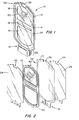
- FIGS. 1-3 show an antenna pedestal 10 for use in an EAS system in accordance with the principles of present invention.
- the antenna pedestal 10 comprises framing means or a frame 12 which extends substantially along or around the perimeter of an antenna casing 14 to hold and support the casing.
- the frame 12 tapers inward and down to form a bottom portion 16, which provides structural support for the antenna casing 14.
- the frame 12 extends all around the casing 14 except for small segments of the perimeter at the top and bottom of the frame.
- the frame 12 thus substantially surrounds the perimeter of the casing 14, i.e., surrounds the casing 14 sufficiently to prevent the casing 14 from being extracted upwardly, downwardly or sideways through the walls of the frame 12.
- the thickness and width of the frame 12 are sufficient to provide structural support for the antenna casing 14, while also improving and reinforcing the structural integrity of the pedestal 10.
- the antenna casing 14 can he held in place by the structure of the frame 12 itself or may be further secured within the frame 12 by an adhesive.
- a lip or channel may be formed in the surface of the frame 12 abutting the antenna casing 14 to allow the antenna casing 14 to be better held in and to the frame.
- Pins, bolts, screws or nails may also be positioned to extend through the frame 12 to engage the antenna casing 14 and to provide further support for the pedestal 10 against shearing forces which might occur when the pedestal 10 is moved.
- the antenna casing 14 also has openings 18 within its structure so that advertisements, printed promotional materials or any type of insert 20 may be placed therein to display various specials, store promotions, etc. Further, the antenna casing 14 encloses and supports an antenna assembly 22, for generating fields used in an EAS system to detect articles having theft deterrent devices or tags attached or secured thereto.
- the frame 12 to hold and support the antenna casing 14 allows the casing 14 to be easily inserted and secured within the frame. This permits easier servicing and replacement of the antenna casing 14 and lessens the amount of materials needed for its construction. Additionally, the frame 12 provides greater strength and structural integrity for the overall pedestal 10 both during use and shipment.
- first and second sheets or plates 24, 26, as best shown in FIG. 2 are also positioned on either side of the antenna casing 14 and are secured to the frame 12.
- the plates 24, 26 are preferably, a transparent plastic material, which cover the length and width of the frame 12 and extend to the edges thereof, and can be adhesively secured to the frame 12. This can be accomplished by using a liquid solvent which is first placed on the outer surfaces of the frame 12 in relation to the position of the plates 24, 26. The plates 24, 26 and the frame 12 are then clamped together by applying vacuum pressure to the plates and frame. This pressure and the influence of the solvent results in the plates 24, 26 and frame 12 becoming adhesively secured in a sandwich-like construction.
- the use of the plates 24, 26 provides greater structural support and integrity to the frame 12.
- the plates 24, 26 also prevent direct access to the antenna casing 14, thereby better protecting it from breakage or damage.
- the bottom portions of the frame 12 and the plates 24, 26 extend downward and are inserted into a base 28 which provides foundation and stability for the overall structure of the pedestal 10.
- the base 28 is smaller in width than the antenna casing 14 and frame 12, which are made relatively wide in order to produce a large zone of coverage of the monitored area.
- FIG. 3 shows in greater detail the assembly of the base 28 of the pedestal 10 without the plates being shown.
- the base 28 includes a cover 30 and a T-section 32a and a clamping bracket 32b.
- the T-section 32a and the clamping bracket 32b help to brace and stabilize the frame 12 and/or plates 24, 26 while also anchoring the pedestal 10 to the floor.
- the cover 30 houses an alarm system (not shown), which is responsive to a disturbance in the magnetic field sensed by the antenna assembly 22.
- the alarm system may comprise an alarm module and driver mounted on a PC board. Further, the alarm system may incorporate a beeping mechanism, which can indicate that an activated tag has passed by the pedestal or a mechanism which provides a voice alert.
- the top portion 34 of the frame 12, as shown in FIGS. 2 and 3, also has a gap 36 therein for positioning of a lamp assembly 38.
- the antenna casing 14 and first and second plates 24, 26 also have corresponding notches 40, 42, 44 respectively, for positioning of the lamp assembly 38.
- the lamp assembly 38 extends along a portion of the perimeter of the antenna casing 14 when positioned in the corresponding gap 36 and notches 40, 42, 44 of the frame 12 and plates 24, 26, respectively.
- the lamp assembly 38 acts as a warning device so that when triggered, the lamp assembly 38 flashes, acting as a visual indicator to notify an employee or security personnel that an article with a theft deterrent tag or device attached thereto is being removed from the store or retail establishment.
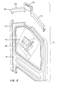
- FIGS. 4 and 5 illustrate a further modification of the antenna pedestal 10 of the invention.
- the frame 12 and the first and second plates 24, 26 are configured so as to form members which when joined together define a pocket having an open top.
- the open top permits the antenna casing 14 to be received and removed from the pocket so that different casings can be used, as well as to permit removal of a casing for repairs, improvements or modifications.
- the frame 12 is provided with a removable cover means or cover 46 which can be joined to or removed from the sides of the frame 12 to close or open the pocket.
- the cover 46 can be joined to the sides of the frame 12 in any suitable manner.
- the cover 46 is formed as a one-piece assembly 48 with the lamp assembly 38 securely or removably positioned thereon. As shown in FIG. 5, the cover 46 is formed of multiple pieces or sections 50. The multiple sections 50 are located on either side of lamp assembly 38, which is a separate section which is removable from the multiple sections 50.
- the antenna pedestal 10 of the present invention is not limited to the illustrated embodiments but may be any length, width or thickness depending upon the structural requirements of the antenna casing or casings to be supported.
- the pedestal may take on oval, rectangular or polygonal configurations to accommodate the antenna casings of a particular EAS system.
- the frame 12 and the plates 24, 26 of the antenna pedestal 10 are preferably made of plastic being a clear, translucent or frosted material and are rigid or semi-rigid in strength to provide adequate structural support for the antenna pedestal 10.
- the use of a clear translucent or frosted material provides for greater visibility through the antenna pedestal 10 in order to observe those activating the alarm while enhancing the overall appearance of the pedestal.
- the base 28 and the lamp assembly 38 may also be plastic, either clear or frosted, but bare preferably a dark colored plastic, in order to conceal the internal workings of the pedestal for security reasons and aesthetics.
- the antenna casing 14 may be composed of a pressed wood or wood paneling structure but may also be formed of a plastic or other rigid or semi-rigid material to support the antenna assembly 22.
- the first and second plates 24, 26, the base 28, the lamp assembly 38 and the frame 12 of the antenna pedestal 10 may also be made of wood or a like rigid material. Semi-flexible materials might also be used as long as the material provides enough structural support to maintain the integrity and shape of the pedestal 10.
- the frame 12, plates 24, 26 and antenna casing 14 of the pedestal 10 may also be assembled and held together by pins, grooves, adhesive or any other retaining means which helps to maintain the structural integrity of the pedestal 10 while also providing further structural support and stability.
- An additional crossmember may also be provided to join the sides of the frame 12 to provide further support for the antenna casing 14 within the frame 12.
Landscapes
- Engineering & Computer Science (AREA)
- Physics & Mathematics (AREA)
- Signal Processing (AREA)
- Automation & Control Theory (AREA)
- Computer Security & Cryptography (AREA)
- Electromagnetism (AREA)
- General Physics & Mathematics (AREA)
- Support Of Aerials (AREA)
- Burglar Alarm Systems (AREA)
Abstract
5 A pedestal for use in an article surveillance system comprises an antenna assembly, an antenna casing for enclosing and supporting the antenna assembly and a frame extending substantially along the perimeter of the antenna casing for holding the antenna casing and including a bottom portion for supporting the antenna casing.
Description
- This invention relates to antenna pedestals, and, in particular, to an antenna pedestal comprising an antenna casing housing an antenna assembly for use in Electronic Article Surveillance ("EAS") systems.
- Typically, an EAS system employs antenna pedestals which are placed and spaced opposite each other at a store entry or exit to allow pedestrian traffic to pass therebetween. Each pedestal may contain an antenna assembly consisting of transmitter and receiver antenna arrays. The antenna arrays of the pedestals generate a magnetic field in the region between the pedestals and allow for detection of a disturbance in the generated magnetic field when an activated theft-deterrent device is passed through the region.
- An example of an antenna pedestal of the above type is the pedestal described in U.S. Patent No. 4,859,991 to Watkins, et al. ("Watkins, et al."). More particularly, Watkins, et al. disclose a pedestal having a complex housing structure for housing an antenna assembly. In the Watkins, et al. pedestal, clam shell members are joined together to form a cavity and foam is used to fill the cavity, thereby immobilizing the antenna assembly and providing rigidity to the pedestal. The pedestal also employs a bumper which is secured around hook-shaped adjacent edges of the clam shell members to help secure the members together.
- Another example of an antenna pedestal for an EAS system is the pedestal disclosed in U.S. Patent No. 4,872,018 to Feltz, et al. ("Feltz, et al."). The Feltz, et al. pedestal merely consists of an antenna array mounted within an antenna casing, formed as a pair of mated hollow support housings.
- While the aforesaid pedestals have proved satisfactory, efforts are still underway to realize antenna pedestals which provide a stronger overall structural support, are less expensive to produce and have the ability to easily permit changing of an antenna assembly within the pedestal without damaging or rebuilding of the pedestal structure. Accordingly, new pedestals having the aforesaid attributes are still being sought.
- It is, therefore, an object of the present invention to provide an antenna pedestal which has greater structural support and integrity.
- It is a further object of the present invention to provide an antenna pedestal which has a simple structure.
- It is an additional object of the present invention to provide an antenna pedestal which allows for easy insertion and removal of an antenna assembly.
- In accordance with the principles of the present invention, the above and other objectives are realized in an antenna pedestal for an EAS system in which the antenna pedestal comprises an antenna casing for enclosing and supporting an antenna assembly and framing means which extends substantially around the perimeter of the antenna casing for holding the antenna casing and including a bottom portion for supporting the antenna casing.
- In a modified form of the antenna pedestal of the invention, first and second plates are disposed on either side of the antenna casing so that the antenna casing is positioned therebetween. These plates are secured to the framing means and provide additional support to the antenna pedestal.
- In a further modification of the antenna pedestal of the invention, the framing means and first and second plates together form joined members which define a pocket having an open top for receiving an antenna casing to be housed within the pocket. The antenna casing is then secured within the pocket by removable cover means which provides a closure for closing the open top of the pocket. The removable cover means may comprise a one-piece or multiple-piece assembly housing a warning device.
- The above and other features and aspects of the present invention will become more apparent upon reading the following detailed description in conjunction with the accompanying drawings, in which:
- FIG. 1 shows a frontal view of an antenna pedestal in accordance with the principles of the present invention;
- FIG. 2 shows an exploded view of the antenna pedestal of FIG. 1 without the base or lamp assembly;
- FIG. 3 shows a view of the antenna pedestal of FIG. 1 with an exploded view of the base and the lamp assembly; and
- FIGS. 4 and 5 show exploded views partially cut away of a modified embodiment of the antenna pedestal of the invention with first and second types of removable cover means, respectively.
- FIGS. 1-3 show an
antenna pedestal 10 for use in an EAS system in accordance with the principles of present invention. As shown in FIGS. 1 and 2, theantenna pedestal 10 comprises framing means or aframe 12 which extends substantially along or around the perimeter of anantenna casing 14 to hold and support the casing. Theframe 12 tapers inward and down to form abottom portion 16, which provides structural support for theantenna casing 14. - As shown in FIG. 2, the
frame 12 extends all around thecasing 14 except for small segments of the perimeter at the top and bottom of the frame. Theframe 12 thus substantially surrounds the perimeter of thecasing 14, i.e., surrounds thecasing 14 sufficiently to prevent thecasing 14 from being extracted upwardly, downwardly or sideways through the walls of theframe 12. As also can be seen in FIG. 2, the thickness and width of theframe 12 are sufficient to provide structural support for theantenna casing 14, while also improving and reinforcing the structural integrity of thepedestal 10. - The
antenna casing 14 can he held in place by the structure of theframe 12 itself or may be further secured within theframe 12 by an adhesive. In addition, a lip or channel may be formed in the surface of theframe 12 abutting theantenna casing 14 to allow theantenna casing 14 to be better held in and to the frame. Pins, bolts, screws or nails may also be positioned to extend through theframe 12 to engage theantenna casing 14 and to provide further support for thepedestal 10 against shearing forces which might occur when thepedestal 10 is moved. - The
antenna casing 14 also hasopenings 18 within its structure so that advertisements, printed promotional materials or any type ofinsert 20 may be placed therein to display various specials, store promotions, etc. Further, theantenna casing 14 encloses and supports anantenna assembly 22, for generating fields used in an EAS system to detect articles having theft deterrent devices or tags attached or secured thereto. - As can be appreciated, use of the
frame 12 to hold and support theantenna casing 14 allows thecasing 14 to be easily inserted and secured within the frame. This permits easier servicing and replacement of theantenna casing 14 and lessens the amount of materials needed for its construction. Additionally, theframe 12 provides greater strength and structural integrity for theoverall pedestal 10 both during use and shipment. - In a modified form of the
pedestal 10, first and second sheets orplates antenna casing 14 and are secured to theframe 12. Theplates frame 12 and extend to the edges thereof, and can be adhesively secured to theframe 12. This can be accomplished by using a liquid solvent which is first placed on the outer surfaces of theframe 12 in relation to the position of theplates plates frame 12 are then clamped together by applying vacuum pressure to the plates and frame. This pressure and the influence of the solvent results in theplates frame 12 becoming adhesively secured in a sandwich-like construction. - The use of the
plates frame 12. Theplates antenna casing 14, thereby better protecting it from breakage or damage. - As shown in FIG. 1, the bottom portions of the
frame 12 and theplates base 28 which provides foundation and stability for the overall structure of thepedestal 10. Thebase 28 is smaller in width than theantenna casing 14 andframe 12, which are made relatively wide in order to produce a large zone of coverage of the monitored area. - FIG. 3 shows in greater detail the assembly of the
base 28 of thepedestal 10 without the plates being shown. Thebase 28 includes acover 30 and a T-section 32a and aclamping bracket 32b. The T-section 32a and theclamping bracket 32b help to brace and stabilize theframe 12 and/orplates pedestal 10 to the floor. Thecover 30 houses an alarm system (not shown), which is responsive to a disturbance in the magnetic field sensed by theantenna assembly 22. The alarm system may comprise an alarm module and driver mounted on a PC board. Further, the alarm system may incorporate a beeping mechanism, which can indicate that an activated tag has passed by the pedestal or a mechanism which provides a voice alert. - The
top portion 34 of theframe 12, as shown in FIGS. 2 and 3, also has agap 36 therein for positioning of alamp assembly 38. Theantenna casing 14 and first andsecond plates corresponding notches lamp assembly 38. Thelamp assembly 38 extends along a portion of the perimeter of theantenna casing 14 when positioned in thecorresponding gap 36 andnotches frame 12 andplates lamp assembly 38 acts as a warning device so that when triggered, thelamp assembly 38 flashes, acting as a visual indicator to notify an employee or security personnel that an article with a theft deterrent tag or device attached thereto is being removed from the store or retail establishment. - FIGS. 4 and 5 illustrate a further modification of the
antenna pedestal 10 of the invention. In this modification, theframe 12 and the first andsecond plates antenna casing 14 to be received and removed from the pocket so that different casings can be used, as well as to permit removal of a casing for repairs, improvements or modifications. - In this case, the
frame 12 is provided with a removable cover means or cover 46 which can be joined to or removed from the sides of theframe 12 to close or open the pocket. Thecover 46 can be joined to the sides of theframe 12 in any suitable manner. - As shown in FIG. 4, the
cover 46 is formed as a one-piece assembly 48 with thelamp assembly 38 securely or removably positioned thereon. As shown in FIG. 5, thecover 46 is formed of multiple pieces orsections 50. Themultiple sections 50 are located on either side oflamp assembly 38, which is a separate section which is removable from themultiple sections 50. - The
antenna pedestal 10 of the present invention is not limited to the illustrated embodiments but may be any length, width or thickness depending upon the structural requirements of the antenna casing or casings to be supported. Thus, for example, the pedestal may take on oval, rectangular or polygonal configurations to accommodate the antenna casings of a particular EAS system. - The
frame 12 and theplates antenna pedestal 10 are preferably made of plastic being a clear, translucent or frosted material and are rigid or semi-rigid in strength to provide adequate structural support for theantenna pedestal 10. The use of a clear translucent or frosted material provides for greater visibility through theantenna pedestal 10 in order to observe those activating the alarm while enhancing the overall appearance of the pedestal. Thebase 28 and thelamp assembly 38 may also be plastic, either clear or frosted, but bare preferably a dark colored plastic, in order to conceal the internal workings of the pedestal for security reasons and aesthetics. - The
antenna casing 14 may be composed of a pressed wood or wood paneling structure but may also be formed of a plastic or other rigid or semi-rigid material to support theantenna assembly 22. The first andsecond plates base 28, thelamp assembly 38 and theframe 12 of theantenna pedestal 10 may also be made of wood or a like rigid material. Semi-flexible materials might also be used as long as the material provides enough structural support to maintain the integrity and shape of thepedestal 10. - The
frame 12,plates antenna casing 14 of thepedestal 10 may also be assembled and held together by pins, grooves, adhesive or any other retaining means which helps to maintain the structural integrity of thepedestal 10 while also providing further structural support and stability. An additional crossmember may also be provided to join the sides of theframe 12 to provide further support for theantenna casing 14 within theframe 12. - In all cases it is understood that the above- described configurations are merely illustrative of the many possible specific embodiments which represent applications of the present invention. Numerous and varied other configurations, can be readily devised in accordance with the principles of the present invention without departing from the spirit and scope of the invention.
Claims (21)
1. A pedestal for use in an article surveillance system, comprising:
an antenna assembly;
an antenna casing for enclosing and supporting said antenna assembly; and
framing means extending substantially along the perimeter of said antenna casing for holding said antenna casing, said framing means including a bottom portion for supporting said antenna casing.
2. A pedestal in accordance with claim 1, further comprising first and second plates, said first and second plates facing each other with said antenna casing positioned therebetween, said first and second plates secured to said framing means.
3. A pedestal in accordance with claim 2, wherein said first and second plates are adhesively secured to said framing means.
4. A pedestal in accordance with claim 3, further comprising a base for supporting the bottom portion of said framing means.
5. A pedestal in accordance with claim 4, wherein said framing means includes a top portion, said top portion having a gap therein.
6. A pedestal in accordance with claim 5, further comprising a lamp assembly positioned in said gap and extending along a portion of the perimeter of said antenna casing.
7. A pedestal in accordance with claim 2, wherein said first and second plates are plastic.
8. A pedestal in accordance with claim 1, wherein said framing means are plastic.
9. A pedestal in accordance with claim 1, wherein said antenna casing includes means for holding advertising material.
10. A pedestal for use in an article surveillance system, comprising:
first and second members; and
means for securing together said first and second members to define a pocket having an open top and adapted to receive an antenna casing to be housed within said pocket.
11. A pedestal in accordance with claim 10, wherein said pocket is further adapted to allow said antenna casing to be removed from said pocket.
12. A pedestal in accordance with claim 11, wherein said securing means includes a frame, said frame extending along the perimeter of said antenna casing for holding said antenna casing and including a bottom portion for supporting said antenna casing.
13. A pedestal in accordance with claim 12, wherein said securing means further comprises an adhesive for securing said first and second members to said frame.
14. A pedestal in accordance with claim 13, further comprising removable cover means, said removable cover means abutting the ends of said frame for closing said open top of said pocket.
15. A pedestal in accordance with claim 14, wherein said removable cover means includes a lamp assembly.
16. A pedestal in accordance with claim 15, wherein said removable cover means comprises multiple sections located on either side of said lamp assembly and positionable in said frame.
17. A pedestal in accordance with claim 16, further comprising a base for supporting said bottom portion of said frame.
18. A pedestal in accordance with claim 12, wherein said first and second members and said frame each comprise plastic.
19. A pedestal in accordance with claim 10, wherein said antenna casing includes means for supporting advertising material.
20. A pedestal in accordance with claim 10, further comprising:
a removable cover, said removable cover being adapted to close said open top of said pocket.
21. A pedestal in accordance with claim 10, wherein said pocket is formed with a bottom portion and said pedestal further comprises a base for supporting said bottom portion.
Applications Claiming Priority (2)
| Application Number | Priority Date | Filing Date | Title |
|---|---|---|---|
| US19884194A | 1994-02-18 | 1994-02-18 | |
| US198841 | 1994-02-18 |
Publications (1)
| Publication Number | Publication Date |
|---|---|
| EP0668626A1 true EP0668626A1 (en) | 1995-08-23 |
Family
ID=22735093
Family Applications (1)
| Application Number | Title | Priority Date | Filing Date |
|---|---|---|---|
| EP94118389A Withdrawn EP0668626A1 (en) | 1994-02-18 | 1994-11-23 | Antenna pedestal |
Country Status (4)
| Country | Link |
|---|---|
| EP (1) | EP0668626A1 (en) |
| JP (1) | JPH07249914A (en) |
| BR (1) | BR9500478A (en) |
| CA (1) | CA2136390A1 (en) |
Cited By (12)
| Publication number | Priority date | Publication date | Assignee | Title |
|---|---|---|---|---|
| DE19726986A1 (en) * | 1997-06-25 | 1999-01-07 | Meto International Gmbh | Device for the surveillance of electronically secured articles in a surveillance zone |
| FR2809279A1 (en) * | 2000-05-18 | 2001-11-23 | Lionel Prat | Shop article anti theft antenna holder having two rigid structure holders placed either side exit point with internal antennas radiating route and outer advertising display. |
| EP1355329A1 (en) * | 2002-04-17 | 2003-10-22 | SENSORMATIC R&D LIMITED | Production of security pedestals |
| FR2843806A1 (en) * | 2002-08-21 | 2004-02-27 | Patrice Vallaud | Anti-theft device, especially for use at the entrance or exit from a shop has transparent antenna supports that are illuminated with LEDs to improve their visibility |
| WO2005057725A1 (en) * | 2003-12-06 | 2005-06-23 | Telegesis (Uk) Ltd | Radio frequency antennae |
| EP1610288A3 (en) * | 2004-06-23 | 2006-08-16 | Heinz-Ullrich Niehues | Supporting device for advertising on antennas of merchandise security systems |
| ES2264620A1 (en) * | 2004-11-25 | 2007-01-01 | Ovelar, S.A. | Trimming cover for anti-theft screen, has semi-housings connected to anti-theft screen and arranged in complementary form, transparent cover provided for semi-housings, and advertisements and posters attached to semi-housings |
| NL1033629C2 (en) * | 2007-04-02 | 2008-10-06 | Nedap Nv | Modular multifunctional antenna frame for an anti-shoplifting system. |
| US20220257032A1 (en) * | 2021-02-15 | 2022-08-18 | Distribución Y Marketing Ltda. | Pedestal alarm |
| WO2024158957A1 (en) * | 2023-01-27 | 2024-08-02 | Checkpoint Systems, Inc. | Modular eas pedestal |
| WO2025010277A1 (en) * | 2023-07-06 | 2025-01-09 | Sensormatic Electronics, LLC | Electronic article surveillance security device and kit |
| USD1068746S1 (en) | 2023-05-01 | 2025-04-01 | Sensormatic Electronics, LLC | Security device |
Families Citing this family (2)
| Publication number | Priority date | Publication date | Assignee | Title |
|---|---|---|---|---|
| KR101734217B1 (en) | 2016-06-30 | 2017-05-12 | (주)인텔리안테크놀로지스 | An pedestal apparatus mounted to an antenna being capable of driving biaxially |
| CA3138422A1 (en) * | 2021-11-10 | 2023-05-10 | Ineo Solutions Inc. | Electronic article surveillance pedestal with extruded framework |
Citations (3)
| Publication number | Priority date | Publication date | Assignee | Title |
|---|---|---|---|---|
| EP0352513A2 (en) * | 1988-07-29 | 1990-01-31 | Knogo Corporation | Load isolated article surveillance system and antenna assembly |
| US5260853A (en) * | 1992-09-28 | 1993-11-09 | Sensormatic Electronics Corporation | Antenna housing assembly with interlocking members |
| US5268699A (en) * | 1992-09-24 | 1993-12-07 | Motorola, Inc. | Data communication receiver utilizing a loop antenna having a hinged connection |
-
1994
- 1994-11-18 JP JP30841094A patent/JPH07249914A/en active Pending
- 1994-11-22 CA CA 2136390 patent/CA2136390A1/en not_active Abandoned
- 1994-11-23 EP EP94118389A patent/EP0668626A1/en not_active Withdrawn
-
1995
- 1995-02-08 BR BR9500478A patent/BR9500478A/en not_active Application Discontinuation
Patent Citations (3)
| Publication number | Priority date | Publication date | Assignee | Title |
|---|---|---|---|---|
| EP0352513A2 (en) * | 1988-07-29 | 1990-01-31 | Knogo Corporation | Load isolated article surveillance system and antenna assembly |
| US5268699A (en) * | 1992-09-24 | 1993-12-07 | Motorola, Inc. | Data communication receiver utilizing a loop antenna having a hinged connection |
| US5260853A (en) * | 1992-09-28 | 1993-11-09 | Sensormatic Electronics Corporation | Antenna housing assembly with interlocking members |
Cited By (20)
| Publication number | Priority date | Publication date | Assignee | Title |
|---|---|---|---|---|
| DE19726986A1 (en) * | 1997-06-25 | 1999-01-07 | Meto International Gmbh | Device for the surveillance of electronically secured articles in a surveillance zone |
| WO1999000778A1 (en) * | 1997-06-25 | 1999-01-07 | Meto International Gmbh | Device for surveying electronically protected items in a surveillance area |
| US6181247B1 (en) | 1997-06-25 | 2001-01-30 | Meto International Gmbh | Device for surveying electronically protected items in a monitored area |
| AU739935B2 (en) * | 1997-06-25 | 2001-10-25 | Meto International Gmbh | Device for surveying electronically protected items in a surveillance area |
| FR2809279A1 (en) * | 2000-05-18 | 2001-11-23 | Lionel Prat | Shop article anti theft antenna holder having two rigid structure holders placed either side exit point with internal antennas radiating route and outer advertising display. |
| EP1355329A1 (en) * | 2002-04-17 | 2003-10-22 | SENSORMATIC R&D LIMITED | Production of security pedestals |
| FR2843806A1 (en) * | 2002-08-21 | 2004-02-27 | Patrice Vallaud | Anti-theft device, especially for use at the entrance or exit from a shop has transparent antenna supports that are illuminated with LEDs to improve their visibility |
| WO2005057725A1 (en) * | 2003-12-06 | 2005-06-23 | Telegesis (Uk) Ltd | Radio frequency antennae |
| EP1610288A3 (en) * | 2004-06-23 | 2006-08-16 | Heinz-Ullrich Niehues | Supporting device for advertising on antennas of merchandise security systems |
| ES2264620B1 (en) * | 2004-11-25 | 2007-11-16 | Ovelar, S.A. | COVER FOR ANTIHURT SCREENS. |
| ES2264620A1 (en) * | 2004-11-25 | 2007-01-01 | Ovelar, S.A. | Trimming cover for anti-theft screen, has semi-housings connected to anti-theft screen and arranged in complementary form, transparent cover provided for semi-housings, and advertisements and posters attached to semi-housings |
| NL1033629C2 (en) * | 2007-04-02 | 2008-10-06 | Nedap Nv | Modular multifunctional antenna frame for an anti-shoplifting system. |
| EP1978593A1 (en) | 2007-04-02 | 2008-10-08 | N.V. Nederlandsche Apparatenfabriek NEDAP | Modular multifunctional antenna frame for an anti-shoplifting system |
| US20220257032A1 (en) * | 2021-02-15 | 2022-08-18 | Distribución Y Marketing Ltda. | Pedestal alarm |
| EP4047575A1 (en) | 2021-02-15 | 2022-08-24 | Distribución y Marketing Ltda. | Pedestal alarm |
| US11700955B2 (en) | 2021-02-15 | 2023-07-18 | Distribucion y Marketing LTDA. | Pedestal alarm |
| WO2024158957A1 (en) * | 2023-01-27 | 2024-08-02 | Checkpoint Systems, Inc. | Modular eas pedestal |
| USD1068746S1 (en) | 2023-05-01 | 2025-04-01 | Sensormatic Electronics, LLC | Security device |
| WO2025010277A1 (en) * | 2023-07-06 | 2025-01-09 | Sensormatic Electronics, LLC | Electronic article surveillance security device and kit |
| US12412974B2 (en) | 2023-07-06 | 2025-09-09 | Sensormatic Electronics, LLC | Electronic article surveillance security device and kit |
Also Published As
| Publication number | Publication date |
|---|---|
| JPH07249914A (en) | 1995-09-26 |
| BR9500478A (en) | 1995-10-24 |
| CA2136390A1 (en) | 1995-08-19 |
Similar Documents
| Publication | Publication Date | Title |
|---|---|---|
| CA2136390A1 (en) | Antenna pedestal | |
| US5680681A (en) | Theft deterrent garment tag with ink identification | |
| US7015815B1 (en) | Anti-theft hanger | |
| US7385522B2 (en) | Portable alarming security device | |
| US8308291B2 (en) | Temple hanger with security device for wire frame glasses | |
| EP0722158B1 (en) | Price indicator mounting apparatus | |
| US6694653B2 (en) | Packaging/display of products | |
| KR101482972B1 (en) | System and method for mounting a badge on a vehicle | |
| US4736539A (en) | Bumper sticker holder | |
| US7299578B2 (en) | Store security device with advertising cover | |
| US5702081A (en) | Bracket apparatus | |
| US6774794B2 (en) | Methods and apparatus for attaching an electronic price label to an electronic theft prevention tag | |
| US5312000A (en) | Anti-theft cosmetic tester display stand and the like | |
| DE69519493D1 (en) | Magnetomechanical goods surveillance label with tunable resonance frequency | |
| US6199309B1 (en) | Merchandising markers accomodating anti-theft sensor | |
| US6250003B1 (en) | Multi-sided display device | |
| AU677507B2 (en) | A theft-deterrent device for attachment to theft-attractive articles | |
| US6257399B1 (en) | Anti-theft display box for a consumer article | |
| US4467543A (en) | Billboard apparatus | |
| US4176486A (en) | Advertising display | |
| US6352606B1 (en) | Consumer article security arrangement | |
| US8646199B2 (en) | Shrink wrap eyeglasses tag with hook | |
| GB9926077D0 (en) | Anti-theft shopping tag with display | |
| US6023871A (en) | Advertising attachment for in-store scanning plate | |
| US10646036B2 (en) | System and associated methods for advertising from a traffic signal control cabinet |
Legal Events
| Date | Code | Title | Description |
|---|---|---|---|
| PUAI | Public reference made under article 153(3) epc to a published international application that has entered the european phase |
Free format text: ORIGINAL CODE: 0009012 |
|
| AK | Designated contracting states |
Kind code of ref document: A1 Designated state(s): DE FR GB SE |
|
| 17P | Request for examination filed |
Effective date: 19950921 |
|
| 17Q | First examination report despatched |
Effective date: 19971120 |
|
| STAA | Information on the status of an ep patent application or granted ep patent |
Free format text: STATUS: THE APPLICATION IS DEEMED TO BE WITHDRAWN |
|
| 18D | Application deemed to be withdrawn |
Effective date: 19980602 |