EP0666580B1 - Improved relay with a movable assembly having a dampening effect - Google Patents
Improved relay with a movable assembly having a dampening effect Download PDFInfo
- Publication number
- EP0666580B1 EP0666580B1 EP95101484A EP95101484A EP0666580B1 EP 0666580 B1 EP0666580 B1 EP 0666580B1 EP 95101484 A EP95101484 A EP 95101484A EP 95101484 A EP95101484 A EP 95101484A EP 0666580 B1 EP0666580 B1 EP 0666580B1
- Authority
- EP
- European Patent Office
- Prior art keywords
- movable
- armature
- relay
- contact
- blade
- Prior art date
- Legal status (The legal status is an assumption and is not a legal conclusion. Google has not performed a legal analysis and makes no representation as to the accuracy of the status listed.)
- Revoked
Links
- 230000000694 effects Effects 0.000 title claims abstract description 5
- 238000006243 chemical reaction Methods 0.000 claims abstract description 6
- 230000005294 ferromagnetic effect Effects 0.000 claims abstract description 6
- 230000005284 excitation Effects 0.000 claims abstract description 5
- 230000003993 interaction Effects 0.000 claims description 2
- 230000008878 coupling Effects 0.000 claims 1
- 238000010168 coupling process Methods 0.000 claims 1
- 238000005859 coupling reaction Methods 0.000 claims 1
- 238000006073 displacement reaction Methods 0.000 description 10
- 238000010586 diagram Methods 0.000 description 7
- 238000013016 damping Methods 0.000 description 5
- 230000005291 magnetic effect Effects 0.000 description 4
- 230000006399 behavior Effects 0.000 description 2
- 238000004140 cleaning Methods 0.000 description 2
- 230000005489 elastic deformation Effects 0.000 description 2
- NFLLKCVHYJRNRH-UHFFFAOYSA-N 8-chloro-1,3-dimethyl-7H-purine-2,6-dione 2-(diphenylmethyl)oxy-N,N-dimethylethanamine Chemical compound O=C1N(C)C(=O)N(C)C2=C1NC(Cl)=N2.C=1C=CC=CC=1C(OCCN(C)C)C1=CC=CC=C1 NFLLKCVHYJRNRH-UHFFFAOYSA-N 0.000 description 1
- 238000004519 manufacturing process Methods 0.000 description 1
Images


Classifications
-
- H—ELECTRICITY
- H01—ELECTRIC ELEMENTS
- H01H—ELECTRIC SWITCHES; RELAYS; SELECTORS; EMERGENCY PROTECTIVE DEVICES
- H01H50/00—Details of electromagnetic relays
- H01H50/16—Magnetic circuit arrangements
- H01H50/18—Movable parts of magnetic circuits, e.g. armature
- H01H50/30—Mechanical arrangements for preventing or damping vibration or shock, e.g. by balancing of armature
- H01H50/305—Mechanical arrangements for preventing or damping vibration or shock, e.g. by balancing of armature damping vibration due to functional movement of armature
-
- H—ELECTRICITY
- H01—ELECTRIC ELEMENTS
- H01H—ELECTRIC SWITCHES; RELAYS; SELECTORS; EMERGENCY PROTECTIVE DEVICES
- H01H50/00—Details of electromagnetic relays
- H01H50/54—Contact arrangements
- H01H50/546—Contact arrangements for contactors having bridging contacts
-
- H—ELECTRICITY
- H01—ELECTRIC ELEMENTS
- H01H—ELECTRIC SWITCHES; RELAYS; SELECTORS; EMERGENCY PROTECTIVE DEVICES
- H01H1/00—Contacts
- H01H1/12—Contacts characterised by the manner in which co-operating contacts engage
- H01H1/14—Contacts characterised by the manner in which co-operating contacts engage by abutting
- H01H1/18—Contacts characterised by the manner in which co-operating contacts engage by abutting with subsequent sliding
-
- H—ELECTRICITY
- H01—ELECTRIC ELEMENTS
- H01H—ELECTRIC SWITCHES; RELAYS; SELECTORS; EMERGENCY PROTECTIVE DEVICES
- H01H1/00—Contacts
- H01H1/12—Contacts characterised by the manner in which co-operating contacts engage
- H01H1/14—Contacts characterised by the manner in which co-operating contacts engage by abutting
- H01H1/22—Contacts characterised by the manner in which co-operating contacts engage by abutting with rigid pivoted member carrying the moving contact
- H01H1/221—Contacts characterised by the manner in which co-operating contacts engage by abutting with rigid pivoted member carrying the moving contact and a contact pressure spring acting between the pivoted member and a supporting member
- H01H1/225—Contacts characterised by the manner in which co-operating contacts engage by abutting with rigid pivoted member carrying the moving contact and a contact pressure spring acting between the pivoted member and a supporting member the supporting member being pivotable
-
- H—ELECTRICITY
- H01—ELECTRIC ELEMENTS
- H01H—ELECTRIC SWITCHES; RELAYS; SELECTORS; EMERGENCY PROTECTIVE DEVICES
- H01H1/00—Contacts
- H01H1/12—Contacts characterised by the manner in which co-operating contacts engage
- H01H1/14—Contacts characterised by the manner in which co-operating contacts engage by abutting
- H01H1/24—Contacts characterised by the manner in which co-operating contacts engage by abutting with resilient mounting
-
- H—ELECTRICITY
- H01—ELECTRIC ELEMENTS
- H01H—ELECTRIC SWITCHES; RELAYS; SELECTORS; EMERGENCY PROTECTIVE DEVICES
- H01H1/00—Contacts
- H01H1/50—Means for increasing contact pressure, preventing vibration of contacts, holding contacts together after engagement, or biasing contacts to the open position
-
- H—ELECTRICITY
- H01—ELECTRIC ELEMENTS
- H01H—ELECTRIC SWITCHES; RELAYS; SELECTORS; EMERGENCY PROTECTIVE DEVICES
- H01H1/00—Contacts
- H01H1/58—Electric connections to or between contacts; Terminals
- H01H1/5822—Flexible connections between movable contact and terminal
-
- H—ELECTRICITY
- H01—ELECTRIC ELEMENTS
- H01H—ELECTRIC SWITCHES; RELAYS; SELECTORS; EMERGENCY PROTECTIVE DEVICES
- H01H50/00—Details of electromagnetic relays
- H01H50/54—Contact arrangements
- H01H50/60—Contact arrangements moving contact being rigidly combined with movable part of magnetic circuit
Definitions
- the present invention refers to a relay, for use particularly in motor-vehicles of the kind defined in the preamble of Claim 1 (US-A-2.517.052).
- a relay comprising a device for dissipating in friction a part of the kinetic energy present in the movable parts at the moment of the closure of the contacts, so as to minimize the bounces.
- Said known device is bulky and complex, and weightens in a considerable manner the movable assembly, with the deriving drawbacks; in fact, by increasing the mass the benefits of the system which tends to dampen the bounces are lost.
- the aim of the present invention is that of eliminating the drawbacks of the known art and in particular to provide a relay that eliminates the bounces, has less wear of the contacts than in the traditional relays and therefore a longer useful life, notwithstanding the fact that it has dimensions and costs substantially equivalent to those of a traditional relay.
- relays of the type of those herein described are used in motor vehicles; all such relays have substantially a structure having a ferromagnetic core, an excitation coil and at least one movable armature or keeper.
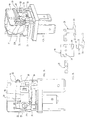
- figure 1 a traditional relay, of the type used in motor vehicles, is schematically represented.
- Reference number 1 indicates an excitation coil wound around a stable core, indicated with reference number 2; reference number 3 indicates the movable assembly, which is composed by:
- Reference number 8 indicates a return spring, for maintaining the armature 4 in the position of maximum air gap with respects to the core 2 when the device is in a release condition; reference number 9 indicates a plait for the electric connection to one of the "faston" connector of the relay (not represented), while reference number 10 indicates a support point for the movable armature 4, when the relay is in the working position; finally reference number 11 indicates an electric closure contact, which is activated when the movable armature 4 is attracted by the core 2.
- figure 3 it is represented the typical elastic characteristic of the movable assembly (3) of a relay of the type being schematically described in figure 1, in a system of Cartesian axis having in abscissa the displacement value, being expressed in micron, and in ordinate the value of the force detected at each displacement, being expressed in centinewton; the portion being highlighted in the diagram of figure 3 represents the foreseen field of work.
- the diagram of figure 3 represents the mechanical gradient "force - displacement" in "the outward journey” (i.e. from the first union of the exchange contacts to the condition of foreseen maximum deformation) and in “the return” (i.e. from the position of foreseen maximum deformation to the position of first union of the exchange contacts) relative to the movable assembly of a relay of the known type.
- Said feature is the main reason of the bounces which are present in the transitory of closure of the contacts on the relays of known type.
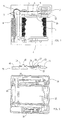
- the movable assembly 3A is equipped a movable blade 15, suitably shaped, which has its fulcrum in a suitable seat 16 obtained in the movable armature 4A; in particular the movable blade 15 presents a bent portion 17, being inserted in the seat 16, building an angle having regards to the main portion which in its opposite end presents an exchange contact 7A; the seat 16 can be advantageously obtained by making a notch on the movable armature 4A; with 18 a relief of the armature 4A is indicated and with 19 an element for the fixing, onto said relief 18, of the leaf spring 5A; the leaf spring 5A presents suitable guides 20, within which two small shoulders 21 are inserted, for limiting the movements, said shoulders being obtained on the movable blade 15.
- the movable blade results in being limited in its possibilities of movement by the leaf spring 5A which, due to the elastic reaction generated on the contact point and to the shoulders 21 being inserted in the suitable guides 20, limits the degree of freedom of the movable blade 15 itself, and transfers to it, and precisely in the angled point where its two portions meet up, the forces being necessary for assuring a closure of the exchange contact 7A, in the condition which should be previously defined in the project.
- FIG 2C there are illustrated in plan view the components of the movable assembly of a relay according to the invention in an embodiment being alternative to that shown in figures 2A and 2B, wherein three reliefs 18 are provided; as it can be imagined from the figures, the inclined portion 17 of the movable blade 15 is inserted in the seat 16 of the armature 4A, the leaf spring 5A is inserted on the reliefs 18 so as that the shoulders 21 results in being restrained in the guides 20, and finally the element 19 is fixed on the reliefs 18, in order to make the armature 4A integral with the leaf spring 5A, with the blade 15 being interposed; the leaf spring 5A is therefore permanently in flexion for maintaining in a constrained position the movable blade 15.
- the main innovation of the relay according to the invention is however due to the presence of a mechanical "hysteresis" on the group of the movable assembly, due to its particular embodiment according to the invention; said hysteresis is apt to damp the kinetic energy accumulated during the transitory of closure (i.e. in the portion of time being necessary to the relay for passing from the release position to the working position) and to annul the bounces which are generated on the system for damping the kinetic energy not damped by the mechanic model.
- figure 4 it is represented the elastic characteristic being typical for the movable assembly of a relay according to the invention, in a system of Cartesian axis having in abscissa the displacement value, being expressed in micron, and in ordinate the value of the force detected at each displacement, being expressed in centinewton; the diagram of figure 4 therefore represents the mechanical gradient "force - displacement" in "the outward journey” (i.e. from the first union of the exchange contacts to the condition of foreseen maximum deformation) and in “the return” (i.e. from the position of foreseen maximum deformation to the position of first union of the exchange contacts) relative to the movable assembly of a relay according to the invention.
- the outward journey i.e. from the first union of the exchange contacts to the condition of foreseen maximum deformation
- the return i.e. from the position of foreseen maximum deformation to the position of first union of the exchange contacts
- the device according to the invention present a loss of charge, or loss of acquired force, of about the 10% in respect of the value measured during the closure phase (said value is a parameter of the project which can be redefined depending upon the functional necessities provided on the particular): this is due to the fact that, being said component an elastic element, but having parts in reciprocal movement, a loss of force exists which can be calculated, and caused by the frictions being present on the system: said portion of force, suitably dimensioned, allows for the total dampening of the bounces present on the contacts during the closure phases, with the consequent increase of the useful life of the component itself.
- the movable assembly of the relay according to the invention presents a portion of force being generated by the frictions among the parts in related movement apt at damping the acquired energy, so as to annul the bounces on the contacts and, therefore, to lengthen the useful life of the components; the comparisons of the diagram of figure 5 (known relay) with the diagram of figure 6 (relay according to the invention) certifies the obtainement of what above said.
- the zone indicated by the arrow in figure 5 highlights the moment of voltage closure on the contacts of a relay of the type of that illustrated in figure 1: as it can be seen the arrow shows at least four closures, i.e. the cited bounces; on the contrary, in the case of figure 6, it can be seen how in the relay according to the invention only one closure is obtained, without any bounces.
- Another important feature which has to be underlined of the relay realized according to the present invention is that, under a parity of displacement of the contact 7A in the closure moment, a translation of the contact point is verified, being greater than that which can be noticed in the relay according to the prior art.
- the present invention can be used on a relay having a normally closed contact; in said application, in the release position an elastic feature of the movable assembly is obtained, being equivalent to that existing on the working contact, with all the advantages applicable to the working condition which can be foreseen on the release contact, with the only reduction of the effects caused by the fact that, for its own nature, a relay of the normally closed type has a contact pressure (therefore a model of working forces) being lower on the release contact.
- the relay according to the invention shows a wear of the contacts being minor to that of the traditional relay, and therefore a longer useful life: this is obtained by means of the reduction of the bounces and by means of the above described self-cleaning system.
- connection plait 9A could be different of that illustrated as an example, and being suitable chosen in order to contribute to the damping effect and avoid resonance in the relay operation.
Landscapes
- Physics & Mathematics (AREA)
- Electromagnetism (AREA)
- Electromagnets (AREA)
- Suspension Of Electric Lines Or Cables (AREA)
- Confectionery (AREA)
- Vibration Prevention Devices (AREA)
- Arrangement Or Mounting Of Propulsion Units For Vehicles (AREA)
- Reciprocating, Oscillating Or Vibrating Motors (AREA)
Abstract
Description
- figure 1 schematically represents in plan view a relay of the known type;
- figure 2 schematically represents in plan view a relay according to the invention;
- figure 2A schematically represents in side view a relay according to the invention:
- figure 2B- schematically represents in perspective view a relay according to the invention;
- figure 2C schematically represents in plan view the component parts of the movable assembly of a relay according to the invention, in a particularly advantageous embodiment;
- figure 3 schematically represents in the form of a diagram the elastic characteristic of the movable assembly of a relay of the known type, in a Cartesian system having in abscissa the displacement value, being expressed in micron, and in ordinate the value of the force detected at each displacement, being expressed in centinewton;
- figure 4 represents with a diagram being similar to that of figure 3, the elastic characteristic being typical of a relay realized according to the invention;
- figure 5 schematically represents the check on the oscilloscope of the bounces being present during the closure of a relay of the known type;
- figure 6 schematically represents the check on the oscilloscope of the bounces being present during the closure of a relay according to the invention;
- figure 7 and 7A schematically represents the portion of the contact being interested by the component of tangential force (difference between the first electric contact point and the contact point at the completed magnetic closure) in a relay of the known type;
- figure 8 and 8A schematically represents the portion of the contact being interested by the component of tangential force (difference between the first electric contact point and the contact point at the completed magnetic closure) in a relay according to the invention.
- a movable ferromagnetic armature, indicated with reference number 4;
- a leaf spring, indicated with
reference number 5, being riveted onto said movable armature 4 in a point indicated withreference number 6; - an electric exchange contact, indicated with
reference number 7.
Claims (7)
- Relay, for the use particularly in motor-vehicles, comprising a stable ferromagnetic core (2A), an excitation coil (1A) wound around said core, a movable assembly (3A), composed by a movable ferromagnetic armature (4A), connected to a blade (15,17) carrying an electric contact (7A), being movable with respect to said armature (4A) and having a fulcrum in an appropriate seat (16) obtained in the said armature (4A), said blade (15,17) being constrained to the armature (4A) in an elastic fashion, but suitable at producing a dampening effect of bouncing phenomenons, said relay also comprising a return spring (8A) to maintain in a position of maximum airgap said movable assembly (3A) with respect to the stable core (2A), when the device is in a release condition, characterized in that a leaf spring (5A) is provided, being fixed in a predetermined point (18) of said movable armature, which constrains for elastic reaction the movement of said movable blade (15) and maintains the desired pressure contact on said electric contact (7A), and said movable blade (15) is suitably shaped and has a portion (17) making up an angle with respect to its main portion and being inserted in said seat (16) obtained in said armature (4A), said movable blade (15,17) being constrained in its movement possibilities by the leaf spring (5A), due to the elastic reaction generated on the point of contact between the leaf spring (5A) and the angled point where the two portions of said movable blade (15,17) meet up.
- Relay according to claim 1, characterized in that said movable blade (15,17) and said leaf spring (5A) have reciprocal coupling means, comprising in particular one or more shoulders (21) of limitation of the movements being obtained onto said movable blade (15) and appropriate guides (20) obtained onto the leaf spring (5A).
- Relay according to claim 1, characterized in that said seat (16) being present in the movable armature (4A) is obtained by making a notch on said armature (4A).
- Relay according to claim 1, characterized in that the interaction of the forces generated by the work necessary for bringing the movable assembly in the magnetically closed position, with the friction being present on the parts in relative movement (4A,5A,17;7A,11A), totally dampen the bounces during the phase of closure of the normally open electric contact (7A).
- Relay according to claim 4, characterized in that the portion of the force taken for mechanical hysteresis is dimensioned in order to give the value considered as being adequate to the type of use of the relay.
- Relay according to claim 5, characterized in that a condition being equivalent to what above described on the transitory of closure of the normally open contact occurs on a normally closed contact.
- Relay according to at least one of the previous claims, characterized in that in the closure phase of said electric contact(7A) it is obtained a substantial sliding of the surface of said exchange contact (7A) on the surface of said closure contact (11A), said sliding being apt at allowing the removal of "micro-peaks" and the levelling of the "micro-craters" which are formed on the surfaces of said contacts (7A,11A).
Applications Claiming Priority (2)
| Application Number | Priority Date | Filing Date | Title |
|---|---|---|---|
| IT94TO000060A IT1268008B1 (en) | 1994-02-04 | 1994-02-04 | RELAIS PERFECTED WITH STILL MOBILE DAMPING EFFECT. |
| ITTO940060 | 1994-02-04 |
Publications (2)
| Publication Number | Publication Date |
|---|---|
| EP0666580A1 EP0666580A1 (en) | 1995-08-09 |
| EP0666580B1 true EP0666580B1 (en) | 1998-06-24 |
Family
ID=11412103
Family Applications (1)
| Application Number | Title | Priority Date | Filing Date |
|---|---|---|---|
| EP95101484A Revoked EP0666580B1 (en) | 1994-02-04 | 1995-02-03 | Improved relay with a movable assembly having a dampening effect |
Country Status (6)
| Country | Link |
|---|---|
| US (1) | US5703549A (en) |
| EP (1) | EP0666580B1 (en) |
| AT (1) | ATE167752T1 (en) |
| DE (1) | DE69503075T2 (en) |
| ES (1) | ES2119239T3 (en) |
| IT (1) | IT1268008B1 (en) |
Families Citing this family (7)
| Publication number | Priority date | Publication date | Assignee | Title |
|---|---|---|---|---|
| DE19544624C1 (en) * | 1995-11-30 | 1997-01-02 | Hella Kg Hueck & Co | Electromagnetic hinged armature relay for motor vehicles |
| DE10162585C1 (en) * | 2001-12-19 | 2003-04-24 | Gruner Ag | Electrical relay has auxiliary spring acting on switched contact spring in closed contact position for reducing rebound |
| DE102004039985A1 (en) * | 2004-08-12 | 2006-02-23 | Alcoa Fujikura Gesellschaft mit beschränkter Haftung | relay |
| US7859372B2 (en) * | 2007-10-24 | 2010-12-28 | Tyco Electronics Corporation | Methods and apparatus for reducing bounce between relay contacts |
| ITBO20070776A1 (en) * | 2007-11-23 | 2009-05-24 | Spal Automotive Srl | VENTILATION UNIT IN PARTICULAR FOR MOTOR VEHICLES. |
| US8373524B1 (en) * | 2012-02-04 | 2013-02-12 | Nilo Villarin | Relay contacts cross connect mitigation |
| IT201800004850A1 (en) * | 2018-04-24 | 2019-10-24 | RELAYS FOR INTRINSICALLY SAFE SYSTEMS |
Family Cites Families (5)
| Publication number | Priority date | Publication date | Assignee | Title |
|---|---|---|---|---|
| US2517052A (en) * | 1945-12-06 | 1950-08-01 | Cutler Hammer Inc | Electric switch |
| US3024333A (en) * | 1959-11-16 | 1962-03-06 | Square D Co | Electrical switch |
| DE4122704C2 (en) * | 1991-07-09 | 1993-12-16 | Siemens Ag | Electromagnetic relay |
| IT1257428B (en) * | 1992-05-20 | 1996-01-16 | Guido Guidi | INTERMEDIATE SUPPORTED RELAY FOR USE IN MOTOR VEHICLES IN PARTICULAR |
| JP2588956Y2 (en) * | 1993-04-14 | 1999-01-20 | ナイルス部品株式会社 | Electromagnetic relay |
-
1994
- 1994-02-04 IT IT94TO000060A patent/IT1268008B1/en active IP Right Grant
-
1995
- 1995-02-03 AT AT95101484T patent/ATE167752T1/en not_active IP Right Cessation
- 1995-02-03 ES ES95101484T patent/ES2119239T3/en not_active Expired - Lifetime
- 1995-02-03 US US08/383,513 patent/US5703549A/en not_active Expired - Fee Related
- 1995-02-03 DE DE69503075T patent/DE69503075T2/en not_active Revoked
- 1995-02-03 EP EP95101484A patent/EP0666580B1/en not_active Revoked
Also Published As
| Publication number | Publication date |
|---|---|
| US5703549A (en) | 1997-12-30 |
| ITTO940060A0 (en) | 1994-02-04 |
| EP0666580A1 (en) | 1995-08-09 |
| IT1268008B1 (en) | 1997-02-20 |
| DE69503075T2 (en) | 1998-12-24 |
| ES2119239T3 (en) | 1998-10-01 |
| ITTO940060A1 (en) | 1995-08-04 |
| ATE167752T1 (en) | 1998-07-15 |
| DE69503075D1 (en) | 1998-07-30 |
Similar Documents
| Publication | Publication Date | Title |
|---|---|---|
| US4638279A (en) | Noiseless electromagnet and a contactor using such an electromagnet | |
| JPS61229977A (en) | Linear motion type actuator | |
| EP0666580A1 (en) | Improved relay with a movable assembly having a dampening effect | |
| Rens et al. | Static performance of a polarized permanent-magnet reluctance actuator for internal combustion engine valve actuation | |
| US4700165A (en) | DC electromagnet equipped with a voltage surge damping device | |
| EP1063666A3 (en) | Electromagnetic trip device | |
| EP1713104B1 (en) | Electromagnetic relay | |
| JPH01253139A (en) | Electromagnetic relay | |
| US4937544A (en) | "Contact arrangement for a relay" | |
| ES2008922A6 (en) | Electromagnetic relay | |
| US5982257A (en) | Integral armature retention spring for electromagnetic relays | |
| US5359306A (en) | Electromagnetic device for controlling the supply of current to the electric starter motor of an internal combustion engine | |
| PL169130B1 (en) | C o ling n ic e le c t e n y PL PL PL | |
| US5319331A (en) | Electromagnetic relay | |
| US5122770A (en) | Alternating current contactor | |
| US5329265A (en) | Intermediate support relay for use particularly in motor vehicles | |
| DE60100200D1 (en) | Electromagnetic actuator with movable coil, in particular for a control valve, with a built-in coil in the elastic element. | |
| JPH082906Y2 (en) | Electromagnetic relay | |
| ITMI960453A1 (en) | ELECTROMAGNETIC PLUGGING RELAY | |
| CN121148955A (en) | A contact system for a relay and a magnetic latching relay | |
| CA1234851A (en) | Monostable type relay | |
| CN119920654A (en) | Automobile relay and control method thereof | |
| WO1999024993A2 (en) | Electromagnet | |
| CA1139807A (en) | Polarized electromagnetic relay | |
| JPH08287790A (en) | Electromagnet for breaker closing operation |
Legal Events
| Date | Code | Title | Description |
|---|---|---|---|
| PUAI | Public reference made under article 153(3) epc to a published international application that has entered the european phase |
Free format text: ORIGINAL CODE: 0009012 |
|
| AK | Designated contracting states |
Kind code of ref document: A1 Designated state(s): AT DE ES FR GB IT PT SE |
|
| RBV | Designated contracting states (corrected) |
Designated state(s): AT DE ES FR GB IT PT SE |
|
| 17P | Request for examination filed |
Effective date: 19960126 |
|
| 17Q | First examination report despatched |
Effective date: 19970131 |
|
| GRAG | Despatch of communication of intention to grant |
Free format text: ORIGINAL CODE: EPIDOS AGRA |
|
| GRAG | Despatch of communication of intention to grant |
Free format text: ORIGINAL CODE: EPIDOS AGRA |
|
| GRAH | Despatch of communication of intention to grant a patent |
Free format text: ORIGINAL CODE: EPIDOS IGRA |
|
| GRAG | Despatch of communication of intention to grant |
Free format text: ORIGINAL CODE: EPIDOS AGRA |
|
| RAP1 | Party data changed (applicant data changed or rights of an application transferred) |
Owner name: BITRON S.P.A. |
|
| GRAH | Despatch of communication of intention to grant a patent |
Free format text: ORIGINAL CODE: EPIDOS IGRA |
|
| GRAA | (expected) grant |
Free format text: ORIGINAL CODE: 0009210 |
|
| RAP1 | Party data changed (applicant data changed or rights of an application transferred) |
Owner name: BITRON S.P.A. |
|
| AK | Designated contracting states |
Kind code of ref document: B1 Designated state(s): AT DE ES FR GB IT PT SE |
|
| PG25 | Lapsed in a contracting state [announced via postgrant information from national office to epo] |
Ref country code: IT Free format text: LAPSE BECAUSE OF FAILURE TO SUBMIT A TRANSLATION OF THE DESCRIPTION OR TO PAY THE FEE WITHIN THE PRESCRIBED TIME-LIMIT;WARNING: LAPSES OF ITALIAN PATENTS WITH EFFECTIVE DATE BEFORE 2007 MAY HAVE OCCURRED AT ANY TIME BEFORE 2007. THE CORRECT EFFECTIVE DATE MAY BE DIFFERENT FROM THE ONE RECORDED. Effective date: 19980624 |
|
| REF | Corresponds to: |
Ref document number: 167752 Country of ref document: AT Date of ref document: 19980715 Kind code of ref document: T |
|
| REF | Corresponds to: |
Ref document number: 69503075 Country of ref document: DE Date of ref document: 19980730 |
|
| REG | Reference to a national code |
Ref country code: ES Ref legal event code: FG2A Ref document number: 2119239 Country of ref document: ES Kind code of ref document: T3 |
|
| ET | Fr: translation filed | ||
| REG | Reference to a national code |
Ref country code: PT Ref legal event code: SC4A Free format text: AVAILABILITY OF NATIONAL TRANSLATION Effective date: 19980625 |
|
| PGFP | Annual fee paid to national office [announced via postgrant information from national office to epo] |
Ref country code: SE Payment date: 19981230 Year of fee payment: 5 |
|
| PGFP | Annual fee paid to national office [announced via postgrant information from national office to epo] |
Ref country code: AT Payment date: 19990113 Year of fee payment: 5 |
|
| PGFP | Annual fee paid to national office [announced via postgrant information from national office to epo] |
Ref country code: GB Payment date: 19990119 Year of fee payment: 5 |
|
| PGFP | Annual fee paid to national office [announced via postgrant information from national office to epo] |
Ref country code: DE Payment date: 19990125 Year of fee payment: 5 |
|
| PGFP | Annual fee paid to national office [announced via postgrant information from national office to epo] |
Ref country code: PT Payment date: 19990127 Year of fee payment: 5 |
|
| PLBI | Opposition filed |
Free format text: ORIGINAL CODE: 0009260 |
|
| PGFP | Annual fee paid to national office [announced via postgrant information from national office to epo] |
Ref country code: ES Payment date: 19990224 Year of fee payment: 5 |
|
| PGFP | Annual fee paid to national office [announced via postgrant information from national office to epo] |
Ref country code: FR Payment date: 19990226 Year of fee payment: 5 |
|
| 26 | Opposition filed |
Opponent name: SIEMENS AKTIENGESELLSCHAFT ZENTRALABTEILUNG TECHNI Effective date: 19990115 |
|
| PLBF | Reply of patent proprietor to notice(s) of opposition |
Free format text: ORIGINAL CODE: EPIDOS OBSO |
|
| PLBF | Reply of patent proprietor to notice(s) of opposition |
Free format text: ORIGINAL CODE: EPIDOS OBSO |
|
| RDAH | Patent revoked |
Free format text: ORIGINAL CODE: EPIDOS REVO |
|
| RDAG | Patent revoked |
Free format text: ORIGINAL CODE: 0009271 |
|
| STAA | Information on the status of an ep patent application or granted ep patent |
Free format text: STATUS: PATENT REVOKED |
|
| 27W | Patent revoked |
Effective date: 19990808 |
|
| GBPR | Gb: patent revoked under art. 102 of the ep convention designating the uk as contracting state |
Free format text: 990808 |
|
| REG | Reference to a national code |
Ref country code: PT Ref legal event code: MF4A Effective date: 19991209 |