EP0665139B1 - Special geometry generant bodies for automotive gas bag inflators - Google Patents
Special geometry generant bodies for automotive gas bag inflators Download PDFInfo
- Publication number
- EP0665139B1 EP0665139B1 EP94309050A EP94309050A EP0665139B1 EP 0665139 B1 EP0665139 B1 EP 0665139B1 EP 94309050 A EP94309050 A EP 94309050A EP 94309050 A EP94309050 A EP 94309050A EP 0665139 B1 EP0665139 B1 EP 0665139B1
- Authority
- EP
- European Patent Office
- Prior art keywords
- generant
- projections
- gas
- body according
- bodies
- Prior art date
- Legal status (The legal status is an assumption and is not a legal conclusion. Google has not performed a legal analysis and makes no representation as to the accuracy of the status listed.)
- Expired - Lifetime
Links
- 238000002485 combustion reaction Methods 0.000 claims description 23
- 239000000203 mixture Substances 0.000 claims description 9
- 150000001540 azides Chemical class 0.000 claims description 7
- 230000002093 peripheral effect Effects 0.000 claims description 3
- 235000012431 wafers Nutrition 0.000 description 66
- 239000007789 gas Substances 0.000 description 50
- 239000003380 propellant Substances 0.000 description 13
- 230000001965 increasing effect Effects 0.000 description 9
- 125000006850 spacer group Chemical group 0.000 description 7
- 239000000463 material Substances 0.000 description 6
- 238000004519 manufacturing process Methods 0.000 description 4
- 230000000694 effects Effects 0.000 description 3
- 230000001788 irregular Effects 0.000 description 3
- 238000000465 moulding Methods 0.000 description 3
- 239000000843 powder Substances 0.000 description 3
- 230000035939 shock Effects 0.000 description 3
- 238000005452 bending Methods 0.000 description 2
- 230000037237 body shape Effects 0.000 description 2
- 238000005336 cracking Methods 0.000 description 2
- 230000003247 decreasing effect Effects 0.000 description 2
- 230000002708 enhancing effect Effects 0.000 description 2
- 231100000252 nontoxic Toxicity 0.000 description 2
- 230000003000 nontoxic effect Effects 0.000 description 2
- 239000007787 solid Substances 0.000 description 2
- 230000035882 stress Effects 0.000 description 2
- BSYNRYMUTXBXSQ-UHFFFAOYSA-N Aspirin Chemical compound CC(=O)OC1=CC=CC=C1C(O)=O BSYNRYMUTXBXSQ-UHFFFAOYSA-N 0.000 description 1
- 229910000831 Steel Inorganic materials 0.000 description 1
- 230000032683 aging Effects 0.000 description 1
- 229940008474 alka-seltzer Drugs 0.000 description 1
- 230000000712 assembly Effects 0.000 description 1
- 238000000429 assembly Methods 0.000 description 1
- 239000006227 byproduct Substances 0.000 description 1
- 239000003795 chemical substances by application Substances 0.000 description 1
- 238000007906 compression Methods 0.000 description 1
- 230000006835 compression Effects 0.000 description 1
- 230000001419 dependent effect Effects 0.000 description 1
- 230000008030 elimination Effects 0.000 description 1
- 238000003379 elimination reaction Methods 0.000 description 1
- 238000001914 filtration Methods 0.000 description 1
- 238000009472 formulation Methods 0.000 description 1
- 238000013467 fragmentation Methods 0.000 description 1
- 238000006062 fragmentation reaction Methods 0.000 description 1
- 239000000446 fuel Substances 0.000 description 1
- 230000003116 impacting effect Effects 0.000 description 1
- 239000007788 liquid Substances 0.000 description 1
- 230000007774 longterm Effects 0.000 description 1
- 230000009972 noncorrosive effect Effects 0.000 description 1
- 231100000956 nontoxicity Toxicity 0.000 description 1
- 239000007800 oxidant agent Substances 0.000 description 1
- 239000008188 pellet Substances 0.000 description 1
- 230000000149 penetrating effect Effects 0.000 description 1
- 238000003825 pressing Methods 0.000 description 1
- 239000000047 product Substances 0.000 description 1
- 230000001681 protective effect Effects 0.000 description 1
- 238000010926 purge Methods 0.000 description 1
- 238000000926 separation method Methods 0.000 description 1
- PERKCQYZRBLRLO-UHFFFAOYSA-M sodium;2-acetyloxybenzoic acid;hydrogen carbonate;2-hydroxypropane-1,2,3-tricarboxylic acid Chemical compound [Na+].OC([O-])=O.CC(=O)OC1=CC=CC=C1C(O)=O.OC(=O)CC(O)(C(O)=O)CC(O)=O PERKCQYZRBLRLO-UHFFFAOYSA-M 0.000 description 1
- 239000010959 steel Substances 0.000 description 1
- 238000003860 storage Methods 0.000 description 1
- 239000002341 toxic gas Substances 0.000 description 1
Images


Classifications
-
- B—PERFORMING OPERATIONS; TRANSPORTING
- B60—VEHICLES IN GENERAL
- B60R—VEHICLES, VEHICLE FITTINGS, OR VEHICLE PARTS, NOT OTHERWISE PROVIDED FOR
- B60R21/00—Arrangements or fittings on vehicles for protecting or preventing injuries to occupants or pedestrians in case of accidents or other traffic risks
- B60R21/02—Occupant safety arrangements or fittings, e.g. crash pads
- B60R21/16—Inflatable occupant restraints or confinements designed to inflate upon impact or impending impact, e.g. air bags
- B60R21/26—Inflatable occupant restraints or confinements designed to inflate upon impact or impending impact, e.g. air bags characterised by the inflation fluid source or means to control inflation fluid flow
- B60R21/264—Inflatable occupant restraints or confinements designed to inflate upon impact or impending impact, e.g. air bags characterised by the inflation fluid source or means to control inflation fluid flow using instantaneous generation of gas, e.g. pyrotechnic
- B60R21/2644—Inflatable occupant restraints or confinements designed to inflate upon impact or impending impact, e.g. air bags characterised by the inflation fluid source or means to control inflation fluid flow using instantaneous generation of gas, e.g. pyrotechnic using only solid reacting substances, e.g. pellets, powder
-
- F—MECHANICAL ENGINEERING; LIGHTING; HEATING; WEAPONS; BLASTING
- F42—AMMUNITION; BLASTING
- F42B—EXPLOSIVE CHARGES, e.g. FOR BLASTING, FIREWORKS, AMMUNITION
- F42B5/00—Cartridge ammunition, e.g. separately-loaded propellant charges
- F42B5/02—Cartridges, i.e. cases with charge and missile
- F42B5/16—Cartridges, i.e. cases with charge and missile characterised by composition or physical dimensions or form of propellant charge, with or without projectile, or powder
Definitions
- the present invention pertains to pyrotechnic bodies, preferably circular wafers and most preferably washer-shaped discs, made of conventional propellant or gas generant compositions which are fabricated to have a special or unique geometry, especially when stacked or arranged in side by side array in the combustion chamber of a gas generator or inflator.
- the inflator produces a gas which, after filtering out condensed phase products, is preferably used to inflate a gas bag which serves as a vehicle occupant cushion during a collision.
- this invention relates to a novel geometry for the generant body wherein a plurality of equally spaced projections which have special size, shape and location are integrally formed (molded) into one or both sides or faces of the body, preferably both, thereby facilitating spacing of plural bodies when stacked or assembled, for example, as an array and preferably side by side in abutting relationship in an inflator thereby enhancing combustion and gas flow during use.
- generant bodies of this invention are especially designed and suited for creating gas for inflating passive restraint vehicle crash bags, it is to be understood that they would function well in other less severe inflation applications, such as aircraft slides, inflatable boats and inflatable lifesaving buoy devices; would more generally find utility any place a low temperature, non-toxic gas is needed, such as for a variety of pressurization and purging applications as, for example, in fuel and oxidizer tanks in rocket motors; and would be useful as a propellant for recoilless rifles and missile systems, particularly in in-tube rocket motors of the short-burning, high-mass type as disclosed in US-A-3,886,006.
- Automobile gas bag systems have been developed to protect the occupant of a vehicle, in the event of a collision, by rapidly inflating a cushion or bag between the vehicle occupant and the interior of the vehicle.
- the inflated gas bag absorbs the occupant's energy to provide a gradual, controlled deceleration, and provides a cushion to distribute body loads and keep the occupant from impacting the hard surfaces of the vehicle interior.
- the requirements of a gas generant suitable for use in an automobile gas bag device are very demanding.
- the gas generant must have a burning rate such that the gas bag is inflated rapidly (within approximately 150 milliseconds).
- the burning rate must not vary with long term storage (aging) or as a result of shock and vibration during normal deployment.
- the burning rate must also be relatively insensitive to changes in humidity and temperature.
- the hardness and mechanical strength of the bodies When pressed into wafers, cylinders, discs or whatever shape, the hardness and mechanical strength of the bodies must be adequate to withstand the mechanical environment to which they may be exposed over the expected inflator system lifetime of at least ten years without any fragmentation or change of surface area. Excessive breakage of the bodies could potentially lead to system failure where, for example, an undesirable high pressure condition might be created within the gas generator device, possibly resulting in rupture of the pressure housing.
- the gas generant must efficiently produce cool, non-toxic, non-corrosive gas which is easily filtered to remove solid and liquid combustion by-products, and thus preclude damage to the inflatable bag or to the occupant of the automobile.
- Inflators such as shown in commonly assigned US-A-4,005,876; 4,296,084 and 4,547,342 contain gas generant in the form of pressed pellets or tablets (similar in shape to ALKA-SELTZER R buffered aspirin) which are randomly packed into the inflator combustion chamber. While such an arrangement may be satisfactory for some purposes, the tablets present a high initial surface area for burning and thus do not provide as soft of an inflation onset as may be desired and achieve low volumetric loading fraction due to the volume lost in the interstitial spaces between tablets.
- an inflator grain or material 60 may be formed by assembling a plurality of cylindrically shaped grains 64 and 66 (Fig. 5), each having an array of axially alignable central and outer peripheral gas passages.
- the end surfaces of the grains are provided with peripherally located projections 158 and 160, and 164 and 166 (Figs. 5 and 8) which abut each other thereby acting as standoffs or spacers thus allowing radial gas flow between grains.
- the plurality of grains require a rather precise and complex assembling operation involving additional features and components to insure proper alignment of the standoff pads and gas passages. This alignment is achieved by placement of a multi-arm retainer device (Fig. 9) about the overall grain 60 which engages V-shaped notches 178 (Fig. 6) and 180 (Fig. 7) in the outer sides of each grain.
- the retainer becomes a permanent part of the inflator.
- US-A-5,101,730 and EP-A-505,024 disclose gas generant bodies according to the precharacterising part of claim 1 having relatively flat-surfaced, similar projections equally spaced about the periphery of at least one side or face of the body, thereby defining lower flat-surfaced sections or spaces between the projections.
- the present invention provides a gas generant body of this type wherein each projection is defined by a first arcuate inside wall which is spaced from a second inside wall and both of which walls emanate from the center of the generant body, curving and flaring outwardly to the peripheral edge of the body, and wherein at least one angular arc length of each projection is significantly greater than the angular arc length of each space therebetween.
- a gas generant body in a configuration that will have superior strength, act as its own spacer and have excellent combustion and gas flow characteristics when stacked or assembled with other similar bodies into an inflator by virtue of its shape, and which will minimize high bending stresses and consequent cracking and igniter shattering effects experienced in similar wafers provided with projections or nubs so configured as to predictably and undesirably allow propagation of cracks along straight lines.
- the gas generant body of the present invention is so configured that it can be easily assembled with like bodies into an inflator independent of orientation and is further incapable of meshing or interlocking with adjoining similar bodies when so assembled and obviates the need for additional features, especially spacers or extra parts in order to assemble or align similar bodies or to maintain a path of radial gas flow when used.
- the dimensions of the arc lengths defined above is the principal feature which permits these wafers, when stacked, to resist meshing or interlocking.
- a preferred characteristic of the embodiments shown is that the outer edge of each projection be contiguous with the wafer perimeter.
- the number of projections or islands on each body face can vary upwards from a minimum of two, preferably at least three, to ten or more. Having such projections on both sides of the body is preferred.
- the projections When on both sides of the body, the projections may be either radially offset or aligned from face to face, preferably in offset relationship.
- the projections may as shown in the figures preferably extend substantially from the inside edge to the outside edge of the body which projections are radially defined by non-intersecting curved lines.
- the preferred gas generant body shape is cylindrical, the most preferred a being washer-shaped disc.
- Another important feature relates to a random assembly or stack of similar generant bodies according to the present invention, preferably made of an azide based composition.
- Still another important feature pertains to a conventional gas generator for an automobile gas bag inflator including a random stack or assembly of similar generant bodies according to the present invention.
- Figs. 1, 2 and 5 show several exemplary embodiments of individual generant bodies or wafers 1 having differently shaped or configured projections 2 on one or both faces or sides.
- a preferred application according to the invention is a random stack or train of the wafers 1 abutting one another, for example, in array 12 as depicted in Fig. 4. And forming the overall grain or combustion array in the combustion chamber of a conventional inflator or gas generator is a preferred application of such an array of wafers 12 which is especially useful for such purposes as rapidly inflating vehicle passive restraint crash protection gas bags, as typically illustrated in aforementioned US-A-4,200,615; 4,890,860 and 4,998,751.
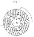
- Fig. 1 shows five projections or raised islands 2 on one side or face of a washer-shaped wafer having a circular opening 9.
- the projections 2 are alike (i.e. have the same cross section) or identical, equally spaced circumferentially about the wafer face, and radially equidistant from the wafer center 11.
- Each projection 2 has the general shape of a curved-wall, irregular polygon (resembling a slice of pie).
- Connecting walls 3 and 3' of the projections are curved (arcuate).
- Each set of spaced, facing arcuate inside walls 3 are parallel and drop perpendicularly to the lower main wafer surfaces 5 and 6.
- Interior curved walls 3' of each projection drop perpendicularly to an annular shelf 6 about the wall 10 of opening 9.
- each angular arc length drawn of the raised sections significantly would exceed the angular arc length of each space 5 therebetween.
- the angular arc length of wall 3' defining the shortest and most interior wall of each projection significantly exceeds the angular arc length of each space 5.
- any total angular arc length (d 1 +d 2 +d 3 +d 4 +d 5 ) of the equal width spaces 5 would be significantly less than the total angular arc length (d 6 +d 7 +d 8 +d 9 +d 10 ) of the spacer pads or raised sections 2.
- any total angular arc length drawn of the spacer pads or raised sections 2 would significantly exceed the total angular arc length of the spaces 5.
- the dimensions of these arc lengths is the feature responsible for these wafers, when stacked in abutting relationship, to resist and prevent meshing or interlocking of adjacent wafers.
- Fig. 2 illustrates another wafer configuration very similar to that of Fig. 1 in that each projection 2 has the general shape of a curved-wall, irregular polygon (resembling a slice of pie).
- the Fig. 2 design has ten projections or pads 2 (instead of five), the curved connecting walls 3 emanate from the interior edge or wall 10 of the circular opening 9 (instead of from an annulus or shelf), and connecting walls 3 slope to the main wafer surface 5 at a 45° angle (instead of a 90° angle).
- the inside wall 3' of each projection forms a contiguous wall with wall 10 of opening 9.
- Fig. 3 is a cross sectional view through plane AA of generant disc or wafer 1 shown in Fig. 2 illustrating the projections 2 on both faces of the wafer, inside curved walls 3 of the projections sloping at 45° angles to the main wafer surfaces 5, and outside walls 7 merging and forming a contiguous wall or plane with the wafer perimeter 8.
- Fig. 4 shows a stacked, randomly oriented array 16 of wafer discs as individually depicted in Fig. 2.
- the wafers forming the stack are randomly oriented because they have been assembled independently of any special orientation which is permitted by the special configuration of the projections on both sides of the wafers, and are incapable of meshing or interlocking.
- Standoff projections or pads 2 form radially random spaces or gaps 13 between and penetrating the interfaces of adjacent wafers 1, which spaces serve as gas flow passages facilitating combustion, especially in a gas generator.
- Fig. 5 illustrates yet another wafer configuration similar to that of Fig. 1 in that each identical projection 2 has the general shape of a curved-wall, irregular polygon. However, Fig. 5 has only three projections or pads 2 (instead of five) and the curved connecting walls 3 emanate from an inner annulus at points 17 equally spaced from the interior edge or wall 10 of the circular opening 9. The outside walls 7 of each projection may, as shown, merge and form a contiguous wall with the wafer perimeter wall 8, though this is not required. Raised sections or pads 2 are equally spaced whereby the angular arc lengths (e 4 - e 6 ) of the spaces therebetween are equal.
- the angular arc lengths (e 1 - e 3 ) of the projections are also equal and exceed the angular arc length of the spaces. Similar to Fig. 1, any total angular arc length (e 1 + e 2 + e 3 ) of the projections is greater than the total angular arc length (e 4 + e 5 + e 6 ) of the spaces. And as in Fig. 2, as long as one or more of the angular arc lengths similarly drawn anywhere along each projection is significantly greater than the angular arc length of the spaces then no meshing or interlocking of similar wafers when stacked would occur.
- the contiguous edge feature produces several advantages and enhanced properties with respect to the overall wafer design shown in Figs. 1-5 not enjoyed by other similar wafer designs; for example, that shown in Figs. 5 and 6 of aforementioned U.S. Pat. No. 4,919,897.
- These properties or advantages are inclusive of (1) increased strength, particularly along the individual wafer perimeters, and durability, (2) ease and simplicity of manufacture, i.e. both from a mold fabrication standpoint as well as molding of the wafers (powder compacts) and (3) increased potential for increasing the individual and total surface area of the projections since access to a larger percentage of the wafer face exists, and (4) less dependency upon the confinement of the wafers on the outside for combustion.
- Burning of the pyrotechnic typically progresses from the inside diameter, where the ignition train is located, to the outside diameters of the wafers.
- the path of flow for hot ignition gases would be obstructed by the raised sections 8, and the area located just outside of the raised sections would not be exposed to the ignition sources until confinement of the gases forces the flow to "turn the corners" (so to speak) and impinge upon these sections. This "turning of the corners” would be dependent upon how much confinement the wafers have on the outside diameter (O.D.). If the O.D. were fully confined, the gases would "turn the corners" fairly easily; whereas if the O.D.
- Each of the projections or pads 2 are integrally formed into a one piece generant body 1, e.g. by hydraulically or mechanically consolidating or pressing a requisite amount of powdered gas generant composition in a suitably designed die (e.g. steel), as is conventional in the art as disclosed in commonly assigned US-A-5,019,220 and the art cited therein.
- the gas generant material may be any known propellant material, for example, any azide or non-azide based composition for automobile gas bag inflators meeting such well known requirements as burning rate, non-toxicity and flame temperature.
- the generant is preferably an azide based composition.
- Exemplary azide-based compositions are disclosed in US-A-3,895,098; 4,203,787; 4,376,002; 4,547,235 and 5,019,220 and in commonly assigned copending application Serial Nos. 07/749,032, filed August 23, 1991, and 07/787,500, filed November 4, 1991, and additional art cited therein.
- Exemplary non-azide based formulations are disclosed in US-A-3,897,285; 3,901,530; 3,901,747 and 4,369,079 and in commonly assigned copending application Serial No. 07/744,755, filed October 9, 1991, and additional art cited therein.
- each projection or pad 2 as shown in the Figures are preferably smooth and flat, i.e. level or parallel to the main surfaces 5 and 6 of the propellant bodies 1; thereby aiding, for example, in generant and stacked generant array strength as well as simplifying fabrication of the shaped bodies of generant.
- the walls 3 of projections 2 descending to the surfaces 5 and 6 of generant bodies 1 can have almost any shape as long as the bodies (individually and collectively) have sufficient strength and the bodies do not present any significant fabrication difficulties including ease of separation from the die press.
- the 45° angled wall 3 as shown in Fig. 2 is preferred.
- Fig. 1 show another embodiment where walls 3 make a straight drop or 90° angle with the generant face. Walls 3 and 3' could also take the form of concave or convex curves or be stepped or tiered.
- the generant body 1 is preferably a wafer, more preferably a disc or cylinder and most preferably a washer-shaped disc as shown in the Figures.
- the overall shape of the propellant body perimeter when used in an inflator, is usually dictated by the shape of the combustion chamber in which the bodies are arranged, as similarly shown in aforementioned US-A-4,890,860.
- many other generant body shapes may be used, such as star-shaped or rectangular (preferably a square).
- central holes or openings 9 are preferred, they may be omitted for certain applications, e.g. a solid multi-wafer grain design as disclosed in aforementioned US-A-4,158,696. Circular shaped openings are most preferred as shown in the Figures.
- the shape of the opening is usually governed by the shape of the igniter chamber on which the generant bodies are preferably arranged, as similarly shown in US-A-4,890,860.
- openings may generally take any shape, such as star-shaped or rectangular (square preferred).
- the perimeter wall 8 of the propellant body, as well as central wall 10 of openings 9 (if used) may be saw-toothed or serrated thereby increasing the generant surface area for combustion or to facilitate grain assembly, etc.
- the Figs. 1 and 2 wafers are more preferred since they produce superior strength, combustion and gas flow properties for reasons to follow.
- the Fig. 2 configuration is most preferred. It is believed that the curved-wall configurations of projections especially of Figs. 1 and 2 reduce the tendency of cracks to propagate along straight lines by minimizing high bending stresses and consequent cracking as well as ignitor shattering effects experienced in similar wafers. It is believed significant that when viewing either side of the wafers shown in Figs. 1 and 2 that the curved walls 3 are so configured that:
- Providing projections 2 on both sides of bodies 1 is also a preferred configuration for whatever projection arrangement is selected, including the embodiments of Figs. 1 and 5.
- the projections (of whatever shape) on one side be radially offset or staggered (i.e. misaligned) with those on the other side because of enhanced wafer and generant body strength (individually and collectively), as well as increased randomness of exposed combustion surfaces and improved overall gas flow when a stacked array (as depicted in Fig. 4) is combusted.
- the smooth curvilinear surfaces of the projections shown in the Figures, especially Figs. 2-4 result in optimum gas flow.
- the wafer configurations shown may have the top and bottom faces of the projections curving either in the same or, preferably, opposite directions as seen from a top sectioned view.
- These raised sections may have a clockwise or, as shown, a counterclockwise curvature or slope, and that curvature or slope may vary considerably, as is depicted in these Figures, preferably on the order of that shown in Fig. 2 so that, as previously indicated, a straight line cannot be drawn diametrically from the edge 10 of wafer opening 9 through any lower section or space 5 without intersecting any raised section.
- the most preferred generant body configuration would be one having curved-wall projections on both faces of the body as shown in Figs.
- the projections would curve in the same direction no matter which wafer face is examined.
- This wafer design would also allow for increased loading when forming an array by stacking similar wafers due to the more distributed load across the surfaces of the wafers.
- the inside walls 3 of the projections in Figs. 1-5 curve outwardly in a counterclockwise fashion, as previously indicated and shown, such direction is not critical, thus they may curve clockwise instead.
- the generant body 1 dimensions are critical and may vary widely. For the most preferred applications, such dimensions would in general follow the typical dimensions well known in the gas bag inflator art as disclosed in aforementioned US-A-4,890,860 and 4,998,751. And in the case of a rectangular generant body the length of the four sides also may vary, but are preferably equal (i.e. a square) or near equal.
- the height of the projections is not critical and can vary widely. The height of the projections may be increased, for example, to minimize the shock effects of combustion; or decreased, for example, to reduce the open area between generant bodies to enhance ignition and reduce the length needed for the overall stack of bodies thereby increasing the volumetric loading fraction.
- the multi-projection generant wafer bodies according to the invention are especially designed to abut one another, they may be used with intervening or alternating smooth surface wafers commonly employed or may be used with inert spacer elements as typified in US-A-3,901,530 and 4,890,860. However, it is advantageous to eliminate the use of such alternating non-gas contributing components in order to achieve more efficient combustion and simplify the inflator design.
- Use of the multi-projection generant bodies 1 of the present invention in a stack allows, for example, for the elimination of extra features and hardware from prior designs, which features and hardware make inflator assembly more difficult and costly as well as increasing the potential for system failure.
- the propellant bodies 1 may be coated in whole or in part with, for example, a combustion modifying material, e.g. an enhancing agent as disclosed in US-A-4,200,615.
Landscapes
- Engineering & Computer Science (AREA)
- Physics & Mathematics (AREA)
- Fluid Mechanics (AREA)
- Mechanical Engineering (AREA)
- General Engineering & Computer Science (AREA)
- Air Bags (AREA)
- Feeding, Discharge, Calcimining, Fusing, And Gas-Generation Devices (AREA)
Description
- FIG. 1
- is a top view of a washer-shaped generant disc having curved projections of one configuration substantially spanning the annular face of the disc;
- FIG. 2
- is a top view of a washer-shaped generant disc having curved projections of another configuration completely spanning the annular face of the disc;
- FIG. 3
- is a cross-sectional view through plane AA of the disc shown in Fig. 2; and
- FIG. 4
- is a space view of a stacked array of discs as shown in Fig. 2.
- FIG. 5
- is a top view of a washer-shaped generant disc having curved projections of another configuration on its face.
Claims (14)
- A gas generant body (1) having a plurality of relatively flat-surfaced, similar projections (2) equally spaced about the periphery of at least one side or face of the body thereby defining lower flat-surfaced sections or spaces (5) between the projections, characterised in that each projection is defined by a first arcuate inside wall (3) which is spaced from a second inside wall (3) and both of which walls emanate from the center (11) of the generant body, curving and flaring outwardly to the peripheral edge (7) of the body, and wherein at least one angular arc length (d6-d10) of each projection is significantly greater than the angular arc length (d1-d5) of each space therebetween.
- A generant body according to claim 1 wherein the outer edge of each projection (2) is contiguous with the perimeter (7) of the body (1).
- A generant body according to claim 1 or claim 2 comprised of an azide based composition.
- A generant body according to claim 1 or claim 2 comprising three said projections (2) on at least one surface thereof.
- A generant body according to claim 1 or claim 2 comprising five said projections (2) on at least one surface thereof.
- A generant body according to claim 1 or claim 2 comprising ten projections.
- A generant body according to claim 1 wherein a plurality of said projections (2) are provided on each of two opposite sides of the body.
- A generant body according to claim 7 wherein said arcuate walls (3) curve in one direction on one said face and in an opposite direction on the opposite face.
- A generant body according to claim 7 or claim 8 wherein the projections (2) on opposite sides of the body are radially aligned.
- A generant body according to claim 7 or claim 8 wherein the projections (2) on opposite sides of the body are radially staggered or offset.
- A gas generant body according to any preceding claim which is of circular shape.
- A gas generant body according to claim 11 which is in the form of a washer-shaped disc.
- A random stack of generant bodies as defined in any preceding claim.
- A gas generator for an automobile gas bag inflator comprising a combustion chamber having a gas outlet, a gas generating grain comprising a random stack of generant bodies as defined in any one of claims 1 to 12 disposed within said chamber, means for igniting said grain, and means for routing gas generated from said chamber through said outlet.
Applications Claiming Priority (2)
| Application Number | Priority Date | Filing Date | Title |
|---|---|---|---|
| US08/185,535 US5551343A (en) | 1994-01-21 | 1994-01-21 | Special geometry generant bodies for automotive gas bag inflator |
| US185535 | 1994-01-21 |
Publications (2)
| Publication Number | Publication Date |
|---|---|
| EP0665139A1 EP0665139A1 (en) | 1995-08-02 |
| EP0665139B1 true EP0665139B1 (en) | 1998-08-12 |
Family
ID=22681391
Family Applications (1)
| Application Number | Title | Priority Date | Filing Date |
|---|---|---|---|
| EP94309050A Expired - Lifetime EP0665139B1 (en) | 1994-01-21 | 1994-12-06 | Special geometry generant bodies for automotive gas bag inflators |
Country Status (4)
| Country | Link |
|---|---|
| US (1) | US5551343A (en) |
| EP (1) | EP0665139B1 (en) |
| JP (1) | JP3013703U (en) |
| DE (1) | DE69412451T2 (en) |
Families Citing this family (20)
| Publication number | Priority date | Publication date | Assignee | Title |
|---|---|---|---|---|
| US6562161B1 (en) * | 1997-03-24 | 2003-05-13 | Daicel Chemical Industries, Ltd. | Gas generating compositions for air bag |
| SE519296C2 (en) | 1997-08-14 | 2003-02-11 | Bofors Defence Ab | The booster module |
| JP2963086B1 (en) | 1997-12-26 | 1999-10-12 | ダイセル化学工業株式会社 | Gas generator and airbag device for airbag |
| US6053110A (en) * | 1998-01-16 | 2000-04-25 | Autoliv Asp, Inc. | Airbag generant wafer design with I-beam construction |
| US6077372A (en) * | 1999-02-02 | 2000-06-20 | Autoliv Development Ab | Ignition enhanced gas generant and method |
| US6502513B1 (en) | 2000-11-17 | 2003-01-07 | Autoliv Asp, Inc. | Tablet form of gas generant |
| US6431072B1 (en) * | 2000-11-30 | 2002-08-13 | The United States Of America As Represented By The Secretary Of The Navy | Propellant grain configuration |
| DE20207861U1 (en) * | 2002-05-21 | 2002-09-26 | TRW Airbag Systems GmbH & Co. KG, 84544 Aschau | Inflator hose |
| US7192055B2 (en) * | 2003-11-13 | 2007-03-20 | Automotive Systems Laboratory, Inc. | Pyrotechnic linear inflator |
| US7243946B2 (en) * | 2003-11-18 | 2007-07-17 | Automotive Systems Laboratory, Inc. | Peroxide linear inflator |
| US20050200103A1 (en) * | 2004-02-27 | 2005-09-15 | Burns Sean P. | Pyrotechnic linear inflator with structural enhancement |
| US7789018B2 (en) * | 2004-04-02 | 2010-09-07 | Automotive Systems Laboratory, Inc. | Gas generator assembly |
| US7293798B2 (en) * | 2004-04-05 | 2007-11-13 | Automotive Systems Laboratory, Inc. | Pyrotechnic linear inflator |
| US8622419B2 (en) * | 2004-07-27 | 2014-01-07 | Automotive Systems Laboratory, Inc. | Vehicle component with integral inflator |
| US7347448B2 (en) * | 2004-10-19 | 2008-03-25 | Autoliv Asp, Inc. | Inflator device for airbag installations |
| JP4625702B2 (en) * | 2005-01-18 | 2011-02-02 | ダイセル化学工業株式会社 | Disc-shaped gas generant molding |
| US7455741B2 (en) * | 2006-01-05 | 2008-11-25 | Autoliv Asp, Inc. | Generant beads for flexible applications |
| US7637533B2 (en) * | 2006-01-25 | 2009-12-29 | Daicel Chemical Industries, Ltd. | Gas generator |
| US8281568B2 (en) * | 2009-06-09 | 2012-10-09 | Raytheon Company | Cartridge-loaded rocket motor with castellated grain segments |
| DE102010049765A1 (en) * | 2010-10-29 | 2012-05-03 | Trw Airbag Systems Gmbh | Process for the preparation of solid propellant tablets, gas generator and module with gas generator |
Family Cites Families (12)
| Publication number | Priority date | Publication date | Assignee | Title |
|---|---|---|---|---|
| US3256819A (en) * | 1964-04-02 | 1966-06-21 | Atlantic Res Corp | Gas generator |
| FR1429725A (en) * | 1964-04-02 | 1966-02-25 | Atlantic Res Corp | Improved configuration solid propellant blocks |
| JPS5747789A (en) * | 1980-09-01 | 1982-03-18 | Nippon Oils & Fats Co Ltd | Sheet-like gunpowder, manufacture and use |
| US4817828A (en) * | 1986-10-03 | 1989-04-04 | Trw Automotive Products Inc. | Inflatable restraint system |
| US4840025A (en) * | 1986-10-14 | 1989-06-20 | General Electric Company | Multiple-propellant air vehicle and propulsion system |
| DE3742656A1 (en) * | 1987-05-22 | 1988-12-08 | Dynamit Nobel Ag | GAS GENERATOR FOR AN AIRBAG |
| FR2625306B1 (en) * | 1987-12-23 | 1993-05-21 | Poudres & Explosifs Ste Nale | AMMUNITION WITH SOCKET COMPRISING A MIXED PROPULSIVE LOADING AND FRAGMENTABLE LOADS IN AGGLOMERATED POWDER FOR CARRYING OUT THIS LOADING |
| DE3923046A1 (en) * | 1989-07-13 | 1991-01-17 | Dynamit Nobel Ag | RING TABLETS FOR GAS GENERATORS |
| ES2088094T3 (en) * | 1991-02-18 | 1996-08-01 | Ici Plc | GAS GENERATOR. |
| US5368329A (en) * | 1993-03-03 | 1994-11-29 | Morton International, Inc. | Dual stage inflator |
| US5385099A (en) * | 1993-03-15 | 1995-01-31 | United Technologies Corporation | Stress relief system for slotted propellant motors |
| US5367872A (en) * | 1993-04-27 | 1994-11-29 | Thiokol Corporation | Method and apparatus for enhancing combustion efficiency of solid fuel hybrid rocket motors |
-
1994
- 1994-01-21 US US08/185,535 patent/US5551343A/en not_active Expired - Lifetime
- 1994-12-06 DE DE69412451T patent/DE69412451T2/en not_active Expired - Lifetime
- 1994-12-06 EP EP94309050A patent/EP0665139B1/en not_active Expired - Lifetime
-
1995
- 1995-01-18 JP JP1995000106U patent/JP3013703U/en not_active Expired - Lifetime
Also Published As
| Publication number | Publication date |
|---|---|
| EP0665139A1 (en) | 1995-08-02 |
| DE69412451D1 (en) | 1998-09-17 |
| DE69412451T2 (en) | 1999-04-15 |
| US5551343A (en) | 1996-09-03 |
| JP3013703U (en) | 1995-07-18 |
Similar Documents
| Publication | Publication Date | Title |
|---|---|---|
| US5551343A (en) | Special geometry generant bodies for automotive gas bag inflator | |
| EP0586045B1 (en) | Gas bag inflator containing inhibited generant | |
| US6053110A (en) | Airbag generant wafer design with I-beam construction | |
| EP0586060B1 (en) | Gas generant body having pressed-on burn inhibitor layer | |
| EP0324639B1 (en) | Wafer grain gas generator | |
| US4817828A (en) | Inflatable restraint system | |
| EP0672560B1 (en) | Extruded generant | |
| US6089598A (en) | Pyrotechnic inflator with reduced extent filter and cartridge charges | |
| JPH03175298A (en) | Gas generator | |
| EP0748724A1 (en) | Air bag filter and seal arrangement | |
| US5578787A (en) | Gas generating agent of air bag inflation gas generator | |
| US5743556A (en) | Inflator flow inhibitor | |
| KR20140052919A (en) | Solid fuel body, gas generator, module having a gas generator, and pyrotechnic drive unit | |
| EP1339573B1 (en) | Tablet form of gas generant | |
| US7789018B2 (en) | Gas generator assembly | |
| US6224098B1 (en) | Gas generator for air bag and air bag system | |
| JP2001278690A (en) | Gas generator for airbag | |
| JPH0592747A (en) | Inflator for air bag | |
| JPH07215165A (en) | Gas generator for airbag |
Legal Events
| Date | Code | Title | Description |
|---|---|---|---|
| PUAI | Public reference made under article 153(3) epc to a published international application that has entered the european phase |
Free format text: ORIGINAL CODE: 0009012 |
|
| AK | Designated contracting states |
Kind code of ref document: A1 Designated state(s): DE FR GB IT |
|
| 17P | Request for examination filed |
Effective date: 19960127 |
|
| 17Q | First examination report despatched |
Effective date: 19970115 |
|
| GRAG | Despatch of communication of intention to grant |
Free format text: ORIGINAL CODE: EPIDOS AGRA |
|
| GRAG | Despatch of communication of intention to grant |
Free format text: ORIGINAL CODE: EPIDOS AGRA |
|
| GRAH | Despatch of communication of intention to grant a patent |
Free format text: ORIGINAL CODE: EPIDOS IGRA |
|
| GRAH | Despatch of communication of intention to grant a patent |
Free format text: ORIGINAL CODE: EPIDOS IGRA |
|
| GRAA | (expected) grant |
Free format text: ORIGINAL CODE: 0009210 |
|
| RAP1 | Party data changed (applicant data changed or rights of an application transferred) |
Owner name: AUTOLIV ASP, INC. |
|
| AK | Designated contracting states |
Kind code of ref document: B1 Designated state(s): DE FR GB IT |
|
| PG25 | Lapsed in a contracting state [announced via postgrant information from national office to epo] |
Ref country code: IT Free format text: LAPSE BECAUSE OF FAILURE TO SUBMIT A TRANSLATION OF THE DESCRIPTION OR TO PAY THE FEE WITHIN THE PRE;WARNING: LAPSES OF ITALIAN PATENTS WITH EFFECTIVE DATE BEFORE 2007 MAY HAVE OCCURRED AT ANY TIME BEFORE 2007. THE CORRECT EFFECTIVE DATE MAY BE DIFFERENT FROM THE ONE RECORDED.SCRIBED TIME-LIMIT Effective date: 19980812 |
|
| REF | Corresponds to: |
Ref document number: 69412451 Country of ref document: DE Date of ref document: 19980917 |
|
| ET | Fr: translation filed | ||
| PLBE | No opposition filed within time limit |
Free format text: ORIGINAL CODE: 0009261 |
|
| STAA | Information on the status of an ep patent application or granted ep patent |
Free format text: STATUS: NO OPPOSITION FILED WITHIN TIME LIMIT |
|
| 26N | No opposition filed | ||
| REG | Reference to a national code |
Ref country code: GB Ref legal event code: IF02 |
|
| PGFP | Annual fee paid to national office [announced via postgrant information from national office to epo] |
Ref country code: GB Payment date: 20101018 Year of fee payment: 17 |
|
| PGFP | Annual fee paid to national office [announced via postgrant information from national office to epo] |
Ref country code: DE Payment date: 20101018 Year of fee payment: 17 |
|
| PGFP | Annual fee paid to national office [announced via postgrant information from national office to epo] |
Ref country code: FR Payment date: 20111028 Year of fee payment: 18 |
|
| GBPC | Gb: european patent ceased through non-payment of renewal fee |
Effective date: 20111206 |
|
| PG25 | Lapsed in a contracting state [announced via postgrant information from national office to epo] |
Ref country code: GB Free format text: LAPSE BECAUSE OF NON-PAYMENT OF DUE FEES Effective date: 20111206 |
|
| REG | Reference to a national code |
Ref country code: FR Ref legal event code: ST Effective date: 20130830 |
|
| REG | Reference to a national code |
Ref country code: DE Ref legal event code: R119 Ref document number: 69412451 Country of ref document: DE Effective date: 20130702 |
|
| PG25 | Lapsed in a contracting state [announced via postgrant information from national office to epo] |
Ref country code: DE Free format text: LAPSE BECAUSE OF NON-PAYMENT OF DUE FEES Effective date: 20130702 |
|
| PG25 | Lapsed in a contracting state [announced via postgrant information from national office to epo] |
Ref country code: FR Free format text: LAPSE BECAUSE OF NON-PAYMENT OF DUE FEES Effective date: 20130102 |