EP0664530A2 - Check out device - Google Patents
Check out device Download PDFInfo
- Publication number
- EP0664530A2 EP0664530A2 EP95100762A EP95100762A EP0664530A2 EP 0664530 A2 EP0664530 A2 EP 0664530A2 EP 95100762 A EP95100762 A EP 95100762A EP 95100762 A EP95100762 A EP 95100762A EP 0664530 A2 EP0664530 A2 EP 0664530A2
- Authority
- EP
- European Patent Office
- Prior art keywords
- article
- settlement section
- settlement
- checkout device
- section
- Prior art date
- Legal status (The legal status is an assumption and is not a legal conclusion. Google has not performed a legal analysis and makes no representation as to the accuracy of the status listed.)
- Withdrawn
Links
Images


Classifications
-
- A—HUMAN NECESSITIES
- A47—FURNITURE; DOMESTIC ARTICLES OR APPLIANCES; COFFEE MILLS; SPICE MILLS; SUCTION CLEANERS IN GENERAL
- A47F—SPECIAL FURNITURE, FITTINGS, OR ACCESSORIES FOR SHOPS, STOREHOUSES, BARS, RESTAURANTS OR THE LIKE; PAYING COUNTERS
- A47F9/00—Shop, bar, bank or like counters
- A47F9/02—Paying counters
- A47F9/04—Check-out counters, e.g. for self-service stores
- A47F9/046—Arrangement of recording means in or on check-out counters
-
- G—PHYSICS
- G07—CHECKING-DEVICES
- G07G—REGISTERING THE RECEIPT OF CASH, VALUABLES, OR TOKENS
- G07G1/00—Cash registers
- G07G1/0036—Checkout procedures
- G07G1/0045—Checkout procedures with a code reader for reading of an identifying code of the article to be registered, e.g. barcode reader or radio-frequency identity [RFID] reader
Definitions
- the present invention relates to a checkout device in which sales transactions for two customers can be effected in parallel.
- FIG. 1 shows a conventional checkout device.
- the checkout device has two scanning lanes L1 and L2 which are symmetrically disposed with respect to the position of a cashier CHR.
- Each of the scanning lanes L1 and L2 has two tables TB1 and TB2 on which a basket BS is placed, and a stationary scanner SC disposed between the tables TB1 and TB2.
- the checkout device has two electronic cash registers CR assigned to and installed between the scanning lanes L1 and L2.
- the scanner SC optically scans and reads an article code affixed to an article in the form of a bar code, and has a switching section SW for instructing start and end of scanning.
- the cash register CR performs a settlement process based on article codes read by the scanner SC.
- a customer CST selects one of the scanning lanes L1 and L2, for example, the scanning lane L1, places the basket BS containing articles to be purchased on the table TB1 on the scanning lane L1 side, and operates the switching section SW to instruct the scanner SC to start scanning.
- the customer CST takes out the articles one by one from the basket BS, causes the scanner SC to read the article code of the article, and puts the article into another basket BS which is previously placed on the table TB2 and is first empty.
- the customer CST operates the switching section SW to instruct the scanner SC to end the scanning.
- the cash register CR on the scanning lane L1 side registers article data (an article name, a unit price, and the like) corresponding to each of the article codes sequentially supplied from the scanner SC as sales data, causes the sales data to be displayed on the cashier display unit DP1 and customer display unit DP2, totalizes all of the sales data items according to the operation of the keyboard KB, and issues a receipt on which the result of totalization containing article names, unit prices, the number of articles, and the total amount is printed by the printer PR.
- the cashier CHR receives these articles from the customer CST and then their article codes by using the keyboard KB, for example.
- the customer inputs the article codes instead of the cashier.
- the cashier has to monitor the customers who input the article codes on the scanning lanes L1 and L2 and carry out an operation of the cash register CR necessary for receiving cash from or giving cash to the customer, it is hardly a burden to the cashier. Further, time for the customer to look on the operation of the cashier without doing anything can be shortened by time corresponding to the input operation carried out by the customer. Therefore, a good impression can be given to the customer.
- the labor cost can be reduced.
- the above checkout device is not widespread due to the following drawback. That is, in supermarkets, the time band of congestion periodically changes depending on the month, week, and day, for example. If article codes are input by a customer who is not familiar with the checkout device, a delay will easily occur in the input operation. This makes the time for waiting customers' turn for the checkout to be lengthened at the time of congestion. Further, both the scanning lanes L1 and L2 will be occupied to input article codes at the time of congestion. If the cashier is dealing with a customer who has finished to input article codes of articles on one scanning lane, the he or she cannot monitor another customer who inputs article codes of articles on the other scanning lane. It is therefore impossible to prevent a dishonesty in which some articles are put in the basket BS on the table TB2 without reading their code.
- An object of the present invention is to provide a checkout device in which quick and smooth checkout is not impaired due to an increase in the number of customers waiting their turn for checkout.
- a checkout device comprising first and second stationary scanners forming central portions of first and second scanning lanes set in parallel with each other, each for reading an article code affixed to an article which is moved from an upstream side to a down stream side in a corresponding scanning lane; and a settlement section arranged between the first and second scanning lanes for performing a settlement process based on article codes sequentially supplied from each of the stationary scanners; and a position adjusting mechanism for variably setting a position of the settlement section along the first and second scanning lanes.
- the position adjusting mechanism variably sets a position of the settlement section along the first and second scanning lanes.
- the settlement section is set at a reference position where it is on a line connecting the first and second stationary scanners
- one operator stands in front of the settlement section to operate it.
- the operator can watch each of two customers who operate the first and second stationary scanners to input article codes.
- the settlement section is set on the upstream side of the reference position
- two operators stand in front of the settlement section between the first and second stationary scanners to operate the settlement section and the first and second scanners.
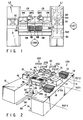
- the checkout device is shown in FIG. 2 and includes two scanning lanes 10A and 10B arranged in parallel to each other and a settlement section 20 disposed between the scanning lanes 10A and 10B.
- Each of the scanning lanes 10A and 10B has a carry-in table 11, stationary scanner 15, and carry-out table 18 disposed on a row.
- the carry-in table 11 is a table on which a basket 12 containing articles to be purchased by a customer is placed.
- the stationary scanner 15 is operated to input article codes affixed in the bar code form to the articles contained in the basket 12. The articles sequentially taken out from the basket 12 are optically scanned to read their codes.
- the carry-out table 18 is a table on which another basket 19 is placed to receive articles whose article codes have been read by the stationary scanner 15.
- the stationary scanner 15 is disposed between the carry-in table 11 and the carry-out table 18 and has a switching section 16 including instruction keys such as a scanning start key and a scanning end key.
- the carry-in table 11 and carry-out table 18 can be one component using a sacker table 1A (1B).
- the settlement section 20 includes electronic cash registers 20A and 20B which are respectively assigned to the scanning lanes 10A and 10B, a housing 30 for unifying the cash registers 20A and 20B, and a drawer 28 common to the electronic cash registers 20A and 20B.
- Each of the electronic cash registers 20A and 20B includes a control section 21U, keyboard 24, handy scanner 25, printer 26, cashier display unit 27CHR, customer display unit 27CST, mode switch 5, receipt issuing port 41, and article table 40.
- the width of the settlement section 20 is set to be as small as possible within an extent that two operators (cashiers) do not feel cramped to operate the settlement section 20.
- the distance between the scanning lanes 10A and 10B is set to be slightly larger than the width of the settlement section 20.
- the control section 21U includes a CPU, ROM and RAM, and performs various mode processes including a settlement process for sequentially registering items of article data (article names, unit prices, and the like) corresponding to article codes sequentially supplied from the stationary scanner 15 on the side of the corresponding scanning lane 10A (10B) as sales data items and totalizing all of the registered sales data items.
- the keyboard 24 is operated by the cashier CHR to input article codes and control instructions necessary for the settlement process.
- the keyboard 24 includes a Tendered/Amount Total key for instructing execution of the account totalization, a plurality of PLU keys for selecting articles such as articles for special sale and vegetables and numerals keys for inputting article codes of various articles.
- the handy scanner 25 is operated by the cashier CHR to selectively read one of the article codes printed on a bar code table sheet in the bar code form for articles such as vegetables and articles for special sale.
- the printer 26 is used to print the result of totalization obtained for all of the registered sales data items on receipt paper.
- the cashier display unit 27CHR and customer display unit 27CST are rotatable so as to face the positions of the cashier CHR and the customer CST-A (CST-B) and display each of the registered sales data items.
- the mode switch 5 is used to select a process mode of the control section 21U according to the position of the inserted key.
- the article table 40 is exposed in a portion between the display units 27CHR, 27CST and the keyboard 24, constructs a lid plate of the housing 30, and is used to temporarily hold an article whose article code is difficult to read by use of the scanner 15 on the corresponding scanning lane 10A (10B) side.
- the article table 40 is set at substantially the same height as the scanner 15.
- the drawer 28 is caused to slide towards the cashier CHR side by the control of each of the control sections 21U of the cash registers 20A and 20B so as to be set into an open state and receive cash which the cashier puts into the drawer.
- the receipt issuing port 41 is an opening formed in part of the article table 40 and permits a receipt supplied from a receipt discharging port 26R of the printer 26 to pass therethrough when the printer 26 is set in the housing 30 and guides the receipt to the cashier CHR side.
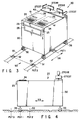
- the checkout device further includes a position adjusting mechanism 50 for variably setting the position of the settlement section 20 along the scanning lanes 10A and 10B.
- the position adjusting mechanism 50 is composed of two rails 51 and 55 mounted on the floor between the scanning lanes 10A and 10B and set in parallel to each other, and four casters 36 fixed to the bottom of the housing 30 of the settlement section 20 and movable on the rails 51 and 55.
- the rails 51 and 55 has plural groups of recesses 52 shown in FIGS. 3 and 4.
- the settlement section 20 is set or fixed at one of three positions PST1, PST2, and PST3 when the casters 52 are received in a corresponding group of the recesses 52.
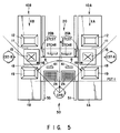
- FIG. 5 shows the checkout device wherein the settlement section 20 is set at the first position PST1.
- the first position PST1 is a reference position at which the settlement section is substantially aligned with the stationary scanners 15 forming central portions of the scanning lanes 10A and 10B, and used for permitting one cashier CHR to operate the cash registers 20A and 20B and two customers CST-A and CST-B to operate the stationary scanners 15.
- FIG. 6 shows the checkout device wherein the settlement section is set at the second position PST2.
- the second position PST2 is a position which is on the upstream side of the reference position PST1, and used for permitting two cashiers CHR-A and CHR-B to operate the stationary scanners 15 of the scanning lanes 10A and 10B and the cash registers 20A and 20B.
- the cashiers CHR-A and CHR-B can be located in front of the settlement section 20 between the stationary scanners 15 of the scanning lanes 10A and 10B.
- FIG. 7 shows the checkout device wherein the settlement section is set at the third position PST3.
- the third position PST3 is a position which is on the downstream side of the reference position PST1, and used for permitting two cashiers CHK-A and CHK-B to operate the stationary scanners 15 of the scanning lanes 10A and 10B and another cashier CHR to operate the cash registers 20A and 20B.
- the cashiers CHK-A and CHK-B can be located behind the settlement section 20 between the stationary scanners 15 of the scanning lanes 10A and 10B and the cashier CHR can be located in front of the settlement section 20.
- each sub-keyboard 24SB includes a plurality of PLU keys for selecting articles such as articles for special sale and vegetables and numerals keys for inputting article codes of various articles, and, as shown in FIG. 7,used on the carry-in tables 11 by the cashiers CHK-A and CHK-B. If the settlement section 20 is set at the position PST1 or PST2, these sub-keyboards are not used and put on shelves formed inside the sacker table 1A and 1B.
- a customer selects one of the scanning lanes 10A and 10B and moves to the selected scanning lane.
- the customer CST-A places on the carry-in table 11 the basket 12 containing articles to be purchased in the scanning lane 10A, and depresses the scanning start key of the switching section 16 in front of the scanner 15.
- the control section 21U of the cash register 20A starts the operation of the scanner 15.
- the customer CST-A takes the articles out of the basket 12 one by one, and inputs their article codes by use of the scanner 15.
- the customer CST-A then puts the articles into another empty basket 19 placed on the carry-out table 18.
- the control section 21U of the cash register 20A sequentially registers article data corresponding to each of the article codes supplied from the scanner 15 as sales data and causes the registered sales data to be displayed on the cashier display unit 27CHR and customer display unit 27CST. After the basket 12 becomes empty, the customer CST-A depresses the end key of the switching section 16. By this key operation, the control section 21U of the cash register 20A stops the operation of the scanner 15. The cashier CHR then depresses the Tendered/Amount Total key provided for execution of the account totalization.
- the control section 21U thus totalizes all of the registered sales data items, causes the printer 26 to print a receipt indicating the result of totalization containing article names, unit prices, the number of articles, and the total amount, and causes the cashier display unit 27CHR and customer display unit 27CST to display the total amount, and opens the drawer 28.
- the cashier CHR hands the receipt printed by the printer 26 and issued via the receipt issuing port 41 to the customer CST-A and puts cash paid by the customer CST-A into the drawer 28.
- the customer CST-A thus completes the checkout, puts all of the articles received in the basket 19 into a shopping bag in a preset place, and then carries the bag.
- the customer CST-B performs an operation for inputting article codes by using the scanner 15 on the scanning lane 10B side in the same manner as in the case of the customer CST-A.
- the cash register 20B performs the same settlement process as that performed by the cash register 20A according to the article codes supplied from the scanner 15 on the scanning lane 10B side.
- the cashier CHR operates the cash register 20B for the customer CST-B as she does the cash register 20A.
- the settlement section 20 performs the settlement processes for the customers CST-A and CST-B in parallel by use of the cash registers 20A and 20B.
- the articles to be purchased by the customer CST-A include an article such as a bargain or vegetables to which no article code in the bar code form is attached or an article whose article code in the bar code form is stained. Since it is hard for the stationary scanner 15 to read the article code from the above article, the cashier CHR must input the article code of the article.
- the customer CST-A places on the article table 40 the article whose article code is difficult to read using the stationary scanner 15.
- the cashier CHR inputs the article code of the article placed on the article table 40 by means of the keyboard 24 or handy scanner 25 and returns the article to the customer CST-A.
- the customer CST-A is able to confirm sales data of an article corresponding to the article code input by the cashier CHR by observing the contents displayed on the customer display unit 27CST.
- the checkout device When the checkout device is in a state shown in FIG. 6, the customer places on the carry-in table 11 the basket 12 containing articles to be purchased in the scanning lane 10A.
- the cashier CHR-A depresses the scanning start key of the switching section 16 in front of the scanner 15.
- the control section 21U of the cash register 20A starts the operation of the scanner 15.
- the cashier CHR-A takes the articles out of the basket 12 one by one, and inputs their article codes by use of the scanner 15.
- the cashier CHR-A then puts the articles into another empty basket 19 placed on the carry-out table 18.
- the control section 21U of the cash register 20A sequentially registers article data corresponding to each of the article codes supplied from the scanner 15 as sales data and causes the registered sales data to be displayed on the cashier display unit 27CHR and customer display unit 27CST. After the basket 12 becomes empty, the cashier CHR-A depresses the end key of the switching section 16. By this key operation, the control section 21U of the cash register 20A stops the operation of the scanner 15. The cashier CHR-A then depresses the Tendered/Amount Total key provided for execution of the account totalization.
- the control section 21U thus totalizes all of the registered sales data items, causes the printer 26 to print a receipt indicating the result of totalization containing article names, unit prices, the number of articles, and the total amount, and causes the cashier display unit 27CHR and customer display unit 27CST to display the total amount, and opens the drawer 28.
- the cashier CHR-A hands the receipt printed by the printer 26 and issued via the receipt issuing port 41 to the customer and puts cash paid by the customer into the drawer 28.
- the customer thus completes the checkout, puts all of the articles received in the basket 19 into a shopping bag in a preset place, and then carries the bag.
- the cashier CHR-B performs an operation for inputting article codes by using the scanner 15 on the scanning lane 10B side in the same manner as in the case of the cashier CHR-A.
- the cash register 20B performs the same settlement process as that performed by the cash register 20A according to the article codes supplied from the scanner 15 on the scanning lane 10B side. Further, the cashier CHR-B operates the cash register 20B for another customer as the cashier CHR-A does the cash register 20A.
- the settlement section 20 performs the settlement processes for the customers in parallel by use of the cash registers 20A and 20B.
- the articles to be purchased by the customer include an article such as a bargain or vegetables to which no article code in the bar code form is attached or an article whose article code in the bar code form is stained.
- the cashier CHR-A (CHR-B) inputs the article code of the article by means of the keyboard 24 or handy scanner 25 and put the article into the basket 19.
- the customer is able to confirm sales data of an article corresponding to the article code input by the cashier CHR-A (CHR-B) by observing the contents displayed on the customer display unit 27CST.
- the checkout device When the checkout device is in a state shown in FIG. 7, the customer places on the carry-in table 11 the basket 12 containing articles to be purchased in the scanning lane 10A.
- the cashier CHK-A depresses the scanning start key of the switching section 16 in front of the scanner 15.
- the control section 21U of the cash register 20A starts the operation of the scanner 15.
- the cashier CHK-A takes the articles out of the basket 12 one by one, and inputs their article codes by use of the scanner 15.
- the cashier CHK-A then puts the articles into another empty basket 19 placed on the carry-out table 18.
- the control section 21U of the cash register 20A sequentially registers article data corresponding to each of the article codes supplied from the scanner 15 as sales data and causes the registered sales data to be displayed on the cashier display unit 27CHR and customer display unit 27CST. After the basket 12 becomes empty, the cashier CHK-A depresses the end key of the switching section 16. By this key operation, the control section 21U of the cash register 20A stops the operation of the scanner 15. The cashier CHR then depresses the Tendered/Amount Total key provided for execution of the account totalization.
- the control section 21U thus totalizes all of the registered sales data items, causes the printer 26 to print a receipt indicating the result of totalization containing article names, unit prices, the number of articles, and the total amount, and causes the cashier display unit 27CHR and customer display unit 27CST to display the total amount, and opens the drawer 28.
- the cashier CHR hands the receipt printed by the printer 26 and issued via the receipt issuing port 41 to the customer and puts cash paid by the customer into the drawer 28.
- the customer thus completes the checkout, puts all of the articles received in the basket 19 into a shopping bag in a preset place, and then carries the bag.
- the cashier CHK-B performs an operation for inputting article codes by using the scanner 15 on the scanning lane 10B side in the same manner as in the case of the cashier CHK-A.
- the cash register 20B performs the same settlement process as that performed by the cash register 20A according to the article codes supplied from the scanner 15 on the scanning lane 10B side.
- the cashier CHR operates the cash register 20B for another customer as she does the cash register 20A.
- the settlement section 20 performs the settlement processes for the customers in parallel by use of the cash registers 20A and 20B.
- the articles to be purchased by the customer include an article such as a bargain or vegetables to which no article code in the bar code form is attached or an article whose article code in the bar code form is stained.
- the cashier CHK-A (CHK-B) inputs the article code of the article by means of the sub-keyboard 24SB and put the article into the basket 19.
- the customer is able to confirm sales data of an article corresponding to the article code input by the cashier CHK-A (CHK-B) by observing the contents displayed on the customer display unit 27CST.
- the position adjusting mechanism 50 variably sets a position of the settlement section 20 along the first and second scanning lanes 10A and 10B. Therefore, the position of the settlement section 20 can be changed without taking much labor.
- the settlement section is set at a reference position PST1 where it is aligned with the first and second stationary scanners 15, one operator stands in front of the settlement section 20 to operate it. In this case, the operator is able to monitor each of two customers who operate the first and second stationary scanners 15 to input article codes.
- the settlement section 20 is set on the upstream side of the reference position PST1, two operators stand in front of the settlement section 20 between the first and second stationary scanners 15 to operate the settlement section 20 and the first and second scanners 15.
- the checkout device can cope with an increase in the number of customers within a limited space.
- the number of operators can be increased in proportion to the number of customers, mental and physical burdens to the operators can be prevented from excessively increasing.
- the article table 40 is prepared for permit an article whose article code is hard to read by the stationary scanner 15 to be placed thereon.
- the cashier cannot immediately receive the article in some cases if the cashier is arranging the cash or checking the amount of money or she is dealing with another customer, for example. If, in such a case, the article is placed on the article table 40, its article code is input when the cashier becomes free. Therefore, the customer can resume the article code input operation immediately after the article whose article code is difficult to read by the stationary scanner 15 is placed on the article table 40. That is, the amount of time the article code input operation is interrupted can be shortened. On the other hand, since the article is not directly handed to the cashier CHR from the customer, the cashier is not forced to interrupt another operation which she is effecting.
- the carry-in table 11 and carry-out table 18 shown in FIG. 2 can be replaced with a pushcart storage space or a belt conveyor.
- the position adjusting mechanism 50 shown in FIG. 3 can be modified as shown in FIG. 8.
- the rails 51 and 55 are replaced with guide bars 2A and 2B fixed to the sacker tables 1A and 1B in parallel.
- the housing 30 of the settlement section 20 is bridged over the guide bars 2A and 2B, and slid along these bars 2A and 2B.
- the guide bars 2A and 2B can reinforce the sacker tables 1A and 1B with supporting the housing30.
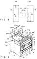
- the settlement section shown in FIG. 2 can be modified as shown in FIGS. 9 and 10.
- the settlement section of the modification includes electronic cash registers 20A and 20B which are respectively assigned to the scanning lanes 10A and 10B, a housing 30 for unifying the cash registers 20A and 20B, and a drawer 28 common to the electronic cash registers 20A and 20B.
- Each of the electronic cash registers 20A and 20B includes a control section 21U, keyboard 24, handy scanner 25, printer 26, cashier display unit 27CHR, customer display unit 27CST, mode switch 5, receipt issuing port 41, and article table 40.
- the housing 30 is constructed by right and left side plates 31, back plate 32, slide plate 24PL, slide guide plate 33, a plurality of support plates 34, base 35, four casters 36, and partition wall 42.
- the slide guide plate 33 and support plates 34 are fixed to the right and left side plates 31 and back plate 32.
- the right and left side plates 31 and back plate 32 are fixed to the base 35.
- the four casters 36 are mounted on the corners of the bottom portion of the base 35 so as to permit the settlement section 20 to be carried along the scanning lanes 10A and 10B.
- the position of the settlement section 20 is fixed by the braking mechanisms of the casters 36.
- the slide plate 24PL is put on the slide guide plate 33 so as to be drawn from the housing 30 towards the cashier CHR.
- the components of the electronic cash registers 20A and 20B are symmetrically arranged as shown in FIG. 9.
- control section 21U is mounted on the support plate 34.
- the control section 21U includes a CPU, ROM and RAM, and performs various mode processes including a settlement process for sequentially registering items of article data (article names, unit prices, and the like) corresponding to article codes sequentially supplied from the stationary scanner 15 on the side of the corresponding scanning lane 10A (10B) as sales data items and totalizing all of the registered sales data items.
- the keyboard 24 is fixed to the slide plate 24PL so as to be exposed at the top of the housing 30 and is operated by the cashier CHR to input article codes and control instructions necessary for the settlement process.
- the keyboard 24 includes a Tendered/Amount Total key for instructing execution of the account totalization, a plurality of PLU keys for selecting articles such as articles for special sale and vegetables and numerals keys for inputting article codes of various articles.
- the handy scanner 25 is set on the end portion of the keyboard 24 on the cashier CHR side and is operated by the cashier CHR to selectively read one of the article codes printed on a bar code table sheet in the bar code form for articles such as vegetables and articles for special sale.
- the printer 26 is fixed to the slide plate 24PL and is used to print the result of totalization obtained for all of the registered sales data items on receipt paper.
- the cashier display unit 27CHR and customer display unit 27CST are exposed at the top of the housing 30 and are respectively set to face the positions of the cashier CHR and the customer CST-A (CST-B) and display each of the registered sales data items.
- the mode switch 5 is fixed to the slide plate 24PL near the keyboard 24 to select a process mode of the control section 21U according to the position of the inserted key.
- the article table 40 is exposed in a portion between the display units 27CHR, 27CST and the keyboard 24, constructs a lid plate of the housing 30, and is used to temporarily hold an article whose article code is difficult to read by use of the scanner 15 on the corresponding scanning lane 10A (10B) side.
- the article table 40 is set at substantially the same height as the scanner 15.
- the partition wall 42 is disposed on the boundary portion between the article table of the cash register 20A and the article table of the cash register 20B.
- the drawer 28 is mounted on the support plate 34 and is caused to slide towards the cashier CHR side by the control of each of the control sections 21U of the cash registers 20A and 20B so as to be set into an open state and receive cash which the cashier puts into the drawer.
- the slide 24PL is normally set such that the end portion of the keyboard 24 will be set in contact with the end portion of the article table 40.
- the printer 26 and mode switch 5 are disposed below the article table 40 and received in the housing 30.
- the slide plate 24PL is drawn as shown in FIG. 5 and the end portion of the keyboard 24 is set in position apart from the end portion of the article table 40.
- the printer 26 and mode switch 5 are exposed from the housing 30 (each cash register can be used irrespective of the position of the slide plate 42).
- the receipt issuing port 41 is an opening formed in part of the article table 40 and permits a receipt supplied from a receipt discharging port 26R of the printer 26 to pass therethrough when the printer 26 is set in the housing 30 and guides the receipt to the cashier CHR side.
- the printer 26 can be exposed simply by drawing the slide plate 24PL towards the cashier CHR. Therefore, the cashier CHR is able to easily and rapidly maintain the printer 26, for example, to supply receipt paper.
- the mode switch 5 is usually fixed to the slide plate 24PL received in the housing 30. It is thus possible to prevent the cashier CHR from operating the mode switch 5 erroneously or another person from operating the same without permission.
- the slide plate 24PL can be slid more smoothly than in the case where the slide plate 24PL is directly placed on the slide guide plate 33.
- the printer 26 is entirely covered with the article table 40 since more articles can be placed on the table 40.
- the article table can be so designed that its part is exposed from the table 40.
Abstract
Description
- The present invention relates to a checkout device in which sales transactions for two customers can be effected in parallel.
- In recent years, a large number of large-scale stores such as supermarkets introduced various types of checkout devices for speeding up the checkout.
- FIG. 1 shows a conventional checkout device. The checkout device has two scanning lanes L1 and L2 which are symmetrically disposed with respect to the position of a cashier CHR. Each of the scanning lanes L1 and L2 has two tables TB1 and TB2 on which a basket BS is placed, and a stationary scanner SC disposed between the tables TB1 and TB2. Further, the checkout device has two electronic cash registers CR assigned to and installed between the scanning lanes L1 and L2. The scanner SC optically scans and reads an article code affixed to an article in the form of a bar code, and has a switching section SW for instructing start and end of scanning. The cash register CR performs a settlement process based on article codes read by the scanner SC.
- A customer CST selects one of the scanning lanes L1 and L2, for example, the scanning lane L1, places the basket BS containing articles to be purchased on the table TB1 on the scanning lane L1 side, and operates the switching section SW to instruct the scanner SC to start scanning. After this, the customer CST takes out the articles one by one from the basket BS, causes the scanner SC to read the article code of the article, and puts the article into another basket BS which is previously placed on the table TB2 and is first empty. After the article codes of all of the articles are input by use of the scanner SC, the customer CST operates the switching section SW to instruct the scanner SC to end the scanning. The cash register CR on the scanning lane L1 side registers article data (an article name, a unit price, and the like) corresponding to each of the article codes sequentially supplied from the scanner SC as sales data, causes the sales data to be displayed on the cashier display unit DP1 and customer display unit DP2, totalizes all of the sales data items according to the operation of the keyboard KB, and issues a receipt on which the result of totalization containing article names, unit prices, the number of articles, and the total amount is printed by the printer PR. As regards the foregoing articles whose article codes are difficult to be input by use of the scanner SC, the cashier CHR receives these articles from the customer CST and then their article codes by using the keyboard KB, for example.
- In the checkout device, the customer inputs the article codes instead of the cashier. Though the cashier has to monitor the customers who input the article codes on the scanning lanes L1 and L2 and carry out an operation of the cash register CR necessary for receiving cash from or giving cash to the customer, it is hardly a burden to the cashier. Further, time for the customer to look on the operation of the cashier without doing anything can be shortened by time corresponding to the input operation carried out by the customer. Therefore, a good impression can be given to the customer. In addition, since one cashier is in charge of two scanning lanes L1 and L2, the labor cost can be reduced.
- Nevertheless, the above checkout device is not widespread due to the following drawback. That is, in supermarkets, the time band of congestion periodically changes depending on the month, week, and day, for example. If article codes are input by a customer who is not familiar with the checkout device, a delay will easily occur in the input operation. This makes the time for waiting customers' turn for the checkout to be lengthened at the time of congestion. Further, both the scanning lanes L1 and L2 will be occupied to input article codes at the time of congestion. If the cashier is dealing with a customer who has finished to input article codes of articles on one scanning lane, the he or she cannot monitor another customer who inputs article codes of articles on the other scanning lane. It is therefore impossible to prevent a dishonesty in which some articles are put in the basket BS on the table TB2 without reading their code.
- An object of the present invention is to provide a checkout device in which quick and smooth checkout is not impaired due to an increase in the number of customers waiting their turn for checkout.
- The above object can be attained by a checkout device comprising first and second stationary scanners forming central portions of first and second scanning lanes set in parallel with each other, each for reading an article code affixed to an article which is moved from an upstream side to a down stream side in a corresponding scanning lane; and a settlement section arranged between the first and second scanning lanes for performing a settlement process based on article codes sequentially supplied from each of the stationary scanners; and a position adjusting mechanism for variably setting a position of the settlement section along the first and second scanning lanes.
- According to the foregoing checkout device, the position adjusting mechanism variably sets a position of the settlement section along the first and second scanning lanes. In a case where the settlement section is set at a reference position where it is on a line connecting the first and second stationary scanners, one operator stands in front of the settlement section to operate it. In this case, the operator can watch each of two customers who operate the first and second stationary scanners to input article codes. In a case where the settlement section is set on the upstream side of the reference position, two operators stand in front of the settlement section between the first and second stationary scanners to operate the settlement section and the first and second scanners. In this case, article codes are input by the two operators, it is possible to eliminate a delay caused when article codes are input by a customer who is not familiar with the checkout device. In a case where the settlement section is set on the down stream side of the reference position, two operators stand behind the settlement section between the first and second stationary scanners to operate first and second stationary scanners and another operator stands in front of the settlement section to operate the settlement section. In this case, the stationary scanners and settlement section are operated by different operators. Therefore, the checkout speed can be enhanced. Consequently, in the aforementioned checkout device, layout of operators can be optimized by varying the position of the settlement according to change in the number of customers waiting their turn for checkout. Therefore, quick and smooth checkout is not impaired due to an increase in the number of customers. Further, the checkout device can cope with an increase in the number of customers within a limited space. In addition, since the number of operators can be increased in proportion to the number of customers, mental and physical burdens to the operators can be prevented from excessively increasing.
- This invention can be more fully understood from the following detailed description when taken in conjunction with the accompanying drawings, in which:
- FIG. 1 is a plan view showing a conventional checkout device to which article codes are input by customers;
- FIG. 2 is a perspective view showing a checkout device according to an embodiment of the present invention;
- FIG. 3 is a perspective view showing a settlement section and position adjusting mechanism shown in FIG. 2;
- FIG. 4 is a view showing positions where the settlement section is variably set by means of the position adjusting mechanism shown in FIG. 3;
- FIG. 5 is a plan view showing the checkout device wherein the settlement section is set at a first position shown in FIG. 4;
- FIG. 6 is a plan view showing the checkout device wherein the settlement section is set at a second position shown in FIG. 4;
- FIG. 7 is a plan view showing the checkout device wherein the settlement section is set at a third section shown in FIG. 4;
- FIG. 8 is a plan view showing a modification of the position adjusting mechanism shown in FIG. 3;
- FIG. 9 is a perspective view showing a modification of the settlement section shown in FIG. 3; and
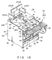
- FIG. 10 is a perspective view showing a structure for exposing a printer provided inside the settlement section shown in FIG. 9 for maintenance.
- There will now be described a checkout device according to an embodiment of the present invention with reference to the accompanying drawings.
- The checkout device is shown in FIG. 2 and includes two
scanning lanes settlement section 20 disposed between thescanning lanes - Each of the
scanning lanes stationary scanner 15, and carry-out table 18 disposed on a row. The carry-in table 11 is a table on which abasket 12 containing articles to be purchased by a customer is placed. Thestationary scanner 15 is operated to input article codes affixed in the bar code form to the articles contained in thebasket 12. The articles sequentially taken out from thebasket 12 are optically scanned to read their codes. The carry-out table 18 is a table on which anotherbasket 19 is placed to receive articles whose article codes have been read by thestationary scanner 15. Thestationary scanner 15 is disposed between the carry-in table 11 and the carry-out table 18 and has aswitching section 16 including instruction keys such as a scanning start key and a scanning end key. The carry-in table 11 and carry-out table 18 can be one component using a sacker table 1A (1B). - The
settlement section 20 includeselectronic cash registers scanning lanes housing 30 for unifying thecash registers drawer 28 common to theelectronic cash registers electronic cash registers keyboard 24,handy scanner 25,printer 26, cashier display unit 27CHR, customer display unit 27CST,mode switch 5,receipt issuing port 41, and article table 40. The width of thesettlement section 20 is set to be as small as possible within an extent that two operators (cashiers) do not feel cramped to operate thesettlement section 20. The distance between thescanning lanes settlement section 20. - In each of the
electronic cash registers stationary scanner 15 on the side of thecorresponding scanning lane 10A (10B) as sales data items and totalizing all of the registered sales data items. Thekeyboard 24 is operated by the cashier CHR to input article codes and control instructions necessary for the settlement process. Thekeyboard 24 includes a Tendered/Amount Total key for instructing execution of the account totalization, a plurality of PLU keys for selecting articles such as articles for special sale and vegetables and numerals keys for inputting article codes of various articles. Thehandy scanner 25 is operated by the cashier CHR to selectively read one of the article codes printed on a bar code table sheet in the bar code form for articles such as vegetables and articles for special sale. Theprinter 26 is used to print the result of totalization obtained for all of the registered sales data items on receipt paper. The cashier display unit 27CHR and customer display unit 27CST are rotatable so as to face the positions of the cashier CHR and the customer CST-A (CST-B) and display each of the registered sales data items. Themode switch 5 is used to select a process mode of the control section 21U according to the position of the inserted key. The article table 40 is exposed in a portion between the display units 27CHR, 27CST and thekeyboard 24, constructs a lid plate of thehousing 30, and is used to temporarily hold an article whose article code is difficult to read by use of thescanner 15 on the correspondingscanning lane 10A (10B) side. The article table 40 is set at substantially the same height as thescanner 15. Thedrawer 28 is caused to slide towards the cashier CHR side by the control of each of the control sections 21U of thecash registers receipt issuing port 41 is an opening formed in part of the article table 40 and permits a receipt supplied from areceipt discharging port 26R of theprinter 26 to pass therethrough when theprinter 26 is set in thehousing 30 and guides the receipt to the cashier CHR side. - The checkout device further includes a
position adjusting mechanism 50 for variably setting the position of thesettlement section 20 along thescanning lanes position adjusting mechanism 50 is composed of tworails scanning lanes casters 36 fixed to the bottom of thehousing 30 of thesettlement section 20 and movable on therails rails recesses 52 shown in FIGS. 3 and 4. Thesettlement section 20 is set or fixed at one of three positions PST1, PST2, and PST3 when thecasters 52 are received in a corresponding group of therecesses 52. - FIG. 5 shows the checkout device wherein the
settlement section 20 is set at the first position PST1. The first position PST1 is a reference position at which the settlement section is substantially aligned with thestationary scanners 15 forming central portions of thescanning lanes cash registers stationary scanners 15. In a state where thesettlement section 20 is set at the first position PST1, the cashier CHR can be located at a position where each of thestationary scanners 15 of thescanning lanes - FIG. 6 shows the checkout device wherein the settlement section is set at the second position PST2. The second position PST2 is a position which is on the upstream side of the reference position PST1, and used for permitting two cashiers CHR-A and CHR-B to operate the
stationary scanners 15 of thescanning lanes cash registers settlement section 20 between thestationary scanners 15 of thescanning lanes - FIG. 7 shows the checkout device wherein the settlement section is set at the third position PST3. The third position PST3 is a position which is on the downstream side of the reference position PST1, and used for permitting two cashiers CHK-A and CHK-B to operate the
stationary scanners 15 of thescanning lanes cash registers settlement section 20 between thestationary scanners 15 of thescanning lanes settlement section 20. In this state, thecash registers settlement section 20 is set at the position PST1 or PST2, these sub-keyboards are not used and put on shelves formed inside the sacker table 1A and 1B. - Next, an operation of the foregoing checkout device will now be described.
- A customer selects one of the
scanning lanes - When the checkout device is in a state shown in FIG. 5, the customer CST-A places on the carry-in table 11 the
basket 12 containing articles to be purchased in thescanning lane 10A, and depresses the scanning start key of theswitching section 16 in front of thescanner 15. By this key operation, the control section 21U of thecash register 20A starts the operation of thescanner 15. The customer CST-A takes the articles out of thebasket 12 one by one, and inputs their article codes by use of thescanner 15. The customer CST-A then puts the articles into anotherempty basket 19 placed on the carry-out table 18. The control section 21U of thecash register 20A sequentially registers article data corresponding to each of the article codes supplied from thescanner 15 as sales data and causes the registered sales data to be displayed on the cashier display unit 27CHR and customer display unit 27CST. After thebasket 12 becomes empty, the customer CST-A depresses the end key of theswitching section 16. By this key operation, the control section 21U of thecash register 20A stops the operation of thescanner 15. The cashier CHR then depresses the Tendered/Amount Total key provided for execution of the account totalization. The control section 21U thus totalizes all of the registered sales data items, causes theprinter 26 to print a receipt indicating the result of totalization containing article names, unit prices, the number of articles, and the total amount, and causes the cashier display unit 27CHR and customer display unit 27CST to display the total amount, and opens thedrawer 28. The cashier CHR hands the receipt printed by theprinter 26 and issued via thereceipt issuing port 41 to the customer CST-A and puts cash paid by the customer CST-A into thedrawer 28. The customer CST-A thus completes the checkout, puts all of the articles received in thebasket 19 into a shopping bag in a preset place, and then carries the bag. - On the other hand, the customer CST-B performs an operation for inputting article codes by using the
scanner 15 on thescanning lane 10B side in the same manner as in the case of the customer CST-A. Thecash register 20B performs the same settlement process as that performed by thecash register 20A according to the article codes supplied from thescanner 15 on thescanning lane 10B side. Further, the cashier CHR operates thecash register 20B for the customer CST-B as she does thecash register 20A. - The
settlement section 20 performs the settlement processes for the customers CST-A and CST-B in parallel by use of thecash registers - Now, assume a case where the articles to be purchased by the customer CST-A include an article such as a bargain or vegetables to which no article code in the bar code form is attached or an article whose article code in the bar code form is stained. Since it is hard for the
stationary scanner 15 to read the article code from the above article, the cashier CHR must input the article code of the article. The customer CST-A then places on the article table 40 the article whose article code is difficult to read using thestationary scanner 15. The cashier CHR inputs the article code of the article placed on the article table 40 by means of thekeyboard 24 orhandy scanner 25 and returns the article to the customer CST-A. The customer CST-A is able to confirm sales data of an article corresponding to the article code input by the cashier CHR by observing the contents displayed on the customer display unit 27CST. - When the checkout device is in a state shown in FIG. 6, the customer places on the carry-in table 11 the
basket 12 containing articles to be purchased in thescanning lane 10A. At this time, the cashier CHR-A depresses the scanning start key of theswitching section 16 in front of thescanner 15. By this key operation, the control section 21U of thecash register 20A starts the operation of thescanner 15. The cashier CHR-A takes the articles out of thebasket 12 one by one, and inputs their article codes by use of thescanner 15. The cashier CHR-A then puts the articles into anotherempty basket 19 placed on the carry-out table 18. The control section 21U of thecash register 20A sequentially registers article data corresponding to each of the article codes supplied from thescanner 15 as sales data and causes the registered sales data to be displayed on the cashier display unit 27CHR and customer display unit 27CST. After thebasket 12 becomes empty, the cashier CHR-A depresses the end key of theswitching section 16. By this key operation, the control section 21U of thecash register 20A stops the operation of thescanner 15. The cashier CHR-A then depresses the Tendered/Amount Total key provided for execution of the account totalization. The control section 21U thus totalizes all of the registered sales data items, causes theprinter 26 to print a receipt indicating the result of totalization containing article names, unit prices, the number of articles, and the total amount, and causes the cashier display unit 27CHR and customer display unit 27CST to display the total amount, and opens thedrawer 28. The cashier CHR-A hands the receipt printed by theprinter 26 and issued via thereceipt issuing port 41 to the customer and puts cash paid by the customer into thedrawer 28. The customer thus completes the checkout, puts all of the articles received in thebasket 19 into a shopping bag in a preset place, and then carries the bag. - On the other hand, the cashier CHR-B performs an operation for inputting article codes by using the
scanner 15 on thescanning lane 10B side in the same manner as in the case of the cashier CHR-A. Thecash register 20B performs the same settlement process as that performed by thecash register 20A according to the article codes supplied from thescanner 15 on thescanning lane 10B side. Further, the cashier CHR-B operates thecash register 20B for another customer as the cashier CHR-A does thecash register 20A. - The
settlement section 20 performs the settlement processes for the customers in parallel by use of thecash registers - Now, assume a case where the articles to be purchased by the customer include an article such as a bargain or vegetables to which no article code in the bar code form is attached or an article whose article code in the bar code form is stained. The cashier CHR-A (CHR-B) inputs the article code of the article by means of the
keyboard 24 orhandy scanner 25 and put the article into thebasket 19. The customer is able to confirm sales data of an article corresponding to the article code input by the cashier CHR-A (CHR-B) by observing the contents displayed on the customer display unit 27CST. - When the checkout device is in a state shown in FIG. 7, the customer places on the carry-in table 11 the
basket 12 containing articles to be purchased in thescanning lane 10A. At this time, the cashier CHK-A depresses the scanning start key of theswitching section 16 in front of thescanner 15. By this key operation, the control section 21U of thecash register 20A starts the operation of thescanner 15. The cashier CHK-A takes the articles out of thebasket 12 one by one, and inputs their article codes by use of thescanner 15. The cashier CHK-A then puts the articles into anotherempty basket 19 placed on the carry-out table 18. The control section 21U of thecash register 20A sequentially registers article data corresponding to each of the article codes supplied from thescanner 15 as sales data and causes the registered sales data to be displayed on the cashier display unit 27CHR and customer display unit 27CST. After thebasket 12 becomes empty, the cashier CHK-A depresses the end key of theswitching section 16. By this key operation, the control section 21U of thecash register 20A stops the operation of thescanner 15. The cashier CHR then depresses the Tendered/Amount Total key provided for execution of the account totalization. The control section 21U thus totalizes all of the registered sales data items, causes theprinter 26 to print a receipt indicating the result of totalization containing article names, unit prices, the number of articles, and the total amount, and causes the cashier display unit 27CHR and customer display unit 27CST to display the total amount, and opens thedrawer 28. The cashier CHR hands the receipt printed by theprinter 26 and issued via thereceipt issuing port 41 to the customer and puts cash paid by the customer into thedrawer 28. The customer thus completes the checkout, puts all of the articles received in thebasket 19 into a shopping bag in a preset place, and then carries the bag. - On the other hand, the cashier CHK-B performs an operation for inputting article codes by using the
scanner 15 on thescanning lane 10B side in the same manner as in the case of the cashier CHK-A. Thecash register 20B performs the same settlement process as that performed by thecash register 20A according to the article codes supplied from thescanner 15 on thescanning lane 10B side. Further, the cashier CHR operates thecash register 20B for another customer as she does thecash register 20A. - The
settlement section 20 performs the settlement processes for the customers in parallel by use of thecash registers - Now, assume a case where the articles to be purchased by the customer include an article such as a bargain or vegetables to which no article code in the bar code form is attached or an article whose article code in the bar code form is stained. The cashier CHK-A (CHK-B) inputs the article code of the article by means of the sub-keyboard 24SB and put the article into the
basket 19. The customer is able to confirm sales data of an article corresponding to the article code input by the cashier CHK-A (CHK-B) by observing the contents displayed on the customer display unit 27CST. - In the checkout device of this embodiment, the
position adjusting mechanism 50 variably sets a position of thesettlement section 20 along the first andsecond scanning lanes settlement section 20 can be changed without taking much labor. In a case where the settlement section is set at a reference position PST1 where it is aligned with the first and secondstationary scanners 15, one operator stands in front of thesettlement section 20 to operate it. In this case, the operator is able to monitor each of two customers who operate the first and secondstationary scanners 15 to input article codes. In a case where thesettlement section 20 is set on the upstream side of the reference position PST1, two operators stand in front of thesettlement section 20 between the first and secondstationary scanners 15 to operate thesettlement section 20 and the first andsecond scanners 15. In this case, article codes are input by the two operators, it is possible to eliminate a delay caused when article codes are input by a customer who is not familiar with the checkout device. In a case where thesettlement section 20 is set on the down stream side of the reference position PST1, two operators stand behind thesettlement section 20 between the first and secondstationary scanners 15 to operate first and secondstationary scanners 15 and another operator stands in front of thesettlement section 20 to operate thesettlement section 20. In this case, thestationary scanners 15 andsettlement section 20 are operated by different operators. Therefore, the checkout speed can be enhanced. Consequently, in the aforementioned checkout device, layout of operators can be optimized by varying the position of the settlement according to change in the number of customers waiting their turn for checkout. Therefore, quick and smooth checkout is not impaired due to an increase in the number of customers. Further, the checkout device can cope with an increase in the number of customers within a limited space. In addition, since the number of operators can be increased in proportion to the number of customers, mental and physical burdens to the operators can be prevented from excessively increasing. - Moreover, the article table 40 is prepared for permit an article whose article code is hard to read by the
stationary scanner 15 to be placed thereon. When the customer encounters such an article during the article code input operation, the cashier cannot immediately receive the article in some cases if the cashier is arranging the cash or checking the amount of money or she is dealing with another customer, for example. If, in such a case, the article is placed on the article table 40, its article code is input when the cashier becomes free. Therefore, the customer can resume the article code input operation immediately after the article whose article code is difficult to read by thestationary scanner 15 is placed on the article table 40. That is, the amount of time the article code input operation is interrupted can be shortened. On the other hand, since the article is not directly handed to the cashier CHR from the customer, the cashier is not forced to interrupt another operation which she is effecting. - The present invention is not limited to the above embodiment and can be variously modified without departing from the scope of the subject matter thereof.
- The carry-in table 11 and carry-out table 18 shown in FIG. 2 can be replaced with a pushcart storage space or a belt conveyor.
- The
position adjusting mechanism 50 shown in FIG. 3 can be modified as shown in FIG. 8. In this modification, therails guide bars housing 30 of thesettlement section 20 is bridged over the guide bars 2A and 2B, and slid along thesebars settlement section 20 and a position sensor for detecting which one of the positions PST1, PST2, and PST3 thesettlement section 20 is located at. - The settlement section shown in FIG. 2 can be modified as shown in FIGS. 9 and 10. The settlement section of the modification includes
electronic cash registers scanning lanes housing 30 for unifying thecash registers drawer 28 common to theelectronic cash registers electronic cash registers keyboard 24,handy scanner 25,printer 26, cashier display unit 27CHR, customer display unit 27CST,mode switch 5,receipt issuing port 41, and article table 40. Thehousing 30 is constructed by right and leftside plates 31, backplate 32, slide plate 24PL, slideguide plate 33, a plurality ofsupport plates 34,base 35, fourcasters 36, andpartition wall 42. Theslide guide plate 33 andsupport plates 34 are fixed to the right and leftside plates 31 and backplate 32. The right and leftside plates 31 and backplate 32 are fixed to thebase 35. The fourcasters 36 are mounted on the corners of the bottom portion of the base 35 so as to permit thesettlement section 20 to be carried along thescanning lanes settlement section 20 is fixed by the braking mechanisms of thecasters 36. The slide plate 24PL is put on theslide guide plate 33 so as to be drawn from thehousing 30 towards the cashier CHR. The components of theelectronic cash registers - In each of the
electronic cash registers support plate 34. The control section 21U includes a CPU, ROM and RAM, and performs various mode processes including a settlement process for sequentially registering items of article data (article names, unit prices, and the like) corresponding to article codes sequentially supplied from thestationary scanner 15 on the side of thecorresponding scanning lane 10A (10B) as sales data items and totalizing all of the registered sales data items. Thekeyboard 24 is fixed to the slide plate 24PL so as to be exposed at the top of thehousing 30 and is operated by the cashier CHR to input article codes and control instructions necessary for the settlement process. Thekeyboard 24 includes a Tendered/Amount Total key for instructing execution of the account totalization, a plurality of PLU keys for selecting articles such as articles for special sale and vegetables and numerals keys for inputting article codes of various articles. Thehandy scanner 25 is set on the end portion of thekeyboard 24 on the cashier CHR side and is operated by the cashier CHR to selectively read one of the article codes printed on a bar code table sheet in the bar code form for articles such as vegetables and articles for special sale. Theprinter 26 is fixed to the slide plate 24PL and is used to print the result of totalization obtained for all of the registered sales data items on receipt paper. The cashier display unit 27CHR and customer display unit 27CST are exposed at the top of thehousing 30 and are respectively set to face the positions of the cashier CHR and the customer CST-A (CST-B) and display each of the registered sales data items. Themode switch 5 is fixed to the slide plate 24PL near thekeyboard 24 to select a process mode of the control section 21U according to the position of the inserted key. The article table 40 is exposed in a portion between the display units 27CHR, 27CST and thekeyboard 24, constructs a lid plate of thehousing 30, and is used to temporarily hold an article whose article code is difficult to read by use of thescanner 15 on the correspondingscanning lane 10A (10B) side. The article table 40 is set at substantially the same height as thescanner 15. - The
partition wall 42 is disposed on the boundary portion between the article table of thecash register 20A and the article table of thecash register 20B. Thedrawer 28 is mounted on thesupport plate 34 and is caused to slide towards the cashier CHR side by the control of each of the control sections 21U of thecash registers - The slide 24PL is normally set such that the end portion of the
keyboard 24 will be set in contact with the end portion of the article table 40. In this condition, theprinter 26 andmode switch 5 are disposed below the article table 40 and received in thehousing 30. At the time of maintenance of theprinter 26, for example, at the time of supply of receipt paper to theprinter 26, the slide plate 24PL is drawn as shown in FIG. 5 and the end portion of thekeyboard 24 is set in position apart from the end portion of the article table 40. As a result, theprinter 26 andmode switch 5 are exposed from the housing 30 (each cash register can be used irrespective of the position of the slide plate 42). Thereceipt issuing port 41 is an opening formed in part of the article table 40 and permits a receipt supplied from areceipt discharging port 26R of theprinter 26 to pass therethrough when theprinter 26 is set in thehousing 30 and guides the receipt to the cashier CHR side. - According to the modification, the
printer 26 can be exposed simply by drawing the slide plate 24PL towards the cashier CHR. Therefore, the cashier CHR is able to easily and rapidly maintain theprinter 26, for example, to supply receipt paper. - The
mode switch 5 is usually fixed to the slide plate 24PL received in thehousing 30. It is thus possible to prevent the cashier CHR from operating themode switch 5 erroneously or another person from operating the same without permission. - In the above modification, it is possible to mount wheels on the bottom surface of the slide plate 24PL and rails on the upper surface of the
slide guide plate 33, and vice versa. In this case, the slide plate 24PL can be slid more smoothly than in the case where the slide plate 24PL is directly placed on theslide guide plate 33. - It is preferable that the
printer 26 is entirely covered with the article table 40 since more articles can be placed on the table 40. However, the article table can be so designed that its part is exposed from the table 40.
Claims (12)
- A checkout device comprising:
first and second stationary scanners forming central portions of first and second scanning lanes (10A, 10B) set in parallel with each other, each for reading an article code affixed to an article which is moved from an upstream side to a down stream side in a corresponding scanning lane; and
a settlement section (20) arranged between said first and second scanning lanes (10A, 10B) for performing a settlement process based on article codes sequentially supplied from each of said stationary scanners (15);
characterized by further comprising position adjusting means (50) for variably setting a position of said settlement section (20) along the first and second scanning lanes (10A, 10B). - A checkout device according to claim 1, characterized in that said position adjusting means (50) includes means for setting said settlement section (20) at a reference position where the settlement section (20) is substantially aligned with said first and second stationary scanners (15).
- A checkout device according to claim 2, characterized in that said position adjusting means (50) includes means for setting said settlement section (20) on an upstream side of the reference position.
- A checkout device according to claim 3, characterized in that said position adjusting means (50) includes means for setting said settlement section (20) on a downstream side of the reference position.
- A checkout device according to claim 2, characterized in that said position adjusting means (50) includes means for setting said settlement section (20) on a downstream side of the reference position.
- A checkout device according to claim 1, characterized in that said position adjusting means (50) includes a plurality of rails (51, 55) set in parallel with each other between said first and second scanning lanes (10A, 10B) and a plurality of casters (36) fixed to a bottom of said settlement section (20) and movable along said rails (51, 55).
- A checkout device according to claim 6, characterized in that said said plurality of rails (51, 55) have a plurality of recesses (52) for receiving said plurality of casters (36) to set the position of said settlement section (20).
- A checkout device according to claim 7, characterized in that said plurality of recesses are provided for at least two of first to third groups of caster positions, said first group of caster positions being for setting said settlement section (20) at the reference position where the settlement section (20) is aligned with said first and second stationary scanners (15), said second group of caster positions being for setting said settlement section (20) on an upstream side of the reference position, and said third group of caster positions being for setting said settlement section (20) on a downstream side of the reference position.
- A checkout device according to claim 1, characterized in that said position adjusting means (50) includes means for setting said settlement section (20) at a reference position for permitting one operator to stand in front of said settlement section (20).
- A checkout device according to claim 9, characterized in that said position adjusting means (50) includes means for setting said settlement section (20) at a position, different from said reference position, for permitting two operators to stand in front of said settlement section (20) between said first and second stationary scanners (15).
- A checkout device according to claim 10, characterized in that said position adjusting means (50) includes means for setting said settlement section (20) at a position, different from said reference position, for permitting two operators to stand behind said settlement section (20) between said first and second stationary scanners (15) and another operator to stand in front of said settlement section (20).
- A checkout device according to claim 9, characterized in that said position adjusting means (50) includes means for setting said settlement section (20) at a position, different from said reference position, for permitting two operators to stand behind said settlement section (20) between said first and second stationary scanners (15) and another operator to stand in front of said settlement section (20).
Applications Claiming Priority (3)
| Application Number | Priority Date | Filing Date | Title |
|---|---|---|---|
| JP541994 | 1994-01-21 | ||
| JP06005419A JP3102982B2 (en) | 1994-01-21 | 1994-01-21 | Scan switching checkout device |
| JP5419/94 | 1994-01-21 |
Publications (2)
| Publication Number | Publication Date |
|---|---|
| EP0664530A2 true EP0664530A2 (en) | 1995-07-26 |
| EP0664530A3 EP0664530A3 (en) | 2000-02-02 |
Family
ID=11610644
Family Applications (1)
| Application Number | Title | Priority Date | Filing Date |
|---|---|---|---|
| EP95100762A Withdrawn EP0664530A3 (en) | 1994-01-21 | 1995-01-20 | Check out device |
Country Status (4)
| Country | Link |
|---|---|
| US (1) | US5492199A (en) |
| EP (1) | EP0664530A3 (en) |
| JP (1) | JP3102982B2 (en) |
| KR (1) | KR0182323B1 (en) |
Cited By (8)
| Publication number | Priority date | Publication date | Assignee | Title |
|---|---|---|---|---|
| EP1098277A3 (en) * | 1999-11-02 | 2006-02-08 | Ncr International Inc. | Apparatus and method for operating convertable checkout system |
| EP1098281A3 (en) * | 1999-11-02 | 2006-02-08 | Ncr International Inc. | Apparatus and method for operating a checkout system |
| EP1098275A3 (en) * | 1999-11-02 | 2006-02-08 | Ncr International Inc. | Apparatus and method for operating a checkout system |
| EP1098274A3 (en) * | 1999-11-02 | 2006-02-08 | Ncr International Inc. | Apparatus and method for operating a checkout system |
| CN101840607A (en) * | 2009-03-17 | 2010-09-22 | 东芝泰格有限公司 | Checkout terminal apparatus |
| DE102011114359A1 (en) * | 2011-09-27 | 2013-03-28 | Awek Gmbh | Cash desk for self-service shop, has goods detecting module that is arranged between goods conveyor and pack region which is arranged at longitudinal side portion along goods conveying direction |
| WO2016013230A1 (en) * | 2014-07-25 | 2016-01-28 | Toshiba Global Commerce Solutions Holdings Corporation | Reconfigurable checkout station |
| EP3361458A1 (en) * | 2017-02-14 | 2018-08-15 | Mago S.A. | Cash register station |
Families Citing this family (13)
| Publication number | Priority date | Publication date | Assignee | Title |
|---|---|---|---|---|
| JP3157686B2 (en) * | 1994-11-08 | 2001-04-16 | 松下電器産業株式会社 | Battery charging control device |
| FR2738734B1 (en) * | 1995-09-20 | 1997-10-17 | Samu | ASSEMBLY FOR THE CONTROL AND RECORDING OF PURCHASES IN A SELF-SERVICE SELLING PLACE |
| US5923017A (en) * | 1997-01-23 | 1999-07-13 | United Parcel Service Of America | Moving-light indicia reader system |
| US5920056A (en) * | 1997-01-23 | 1999-07-06 | United Parcel Service Of America, Inc. | Optically-guided indicia reader system for assisting in positioning a parcel on a conveyor |
| US6588549B2 (en) * | 2001-07-06 | 2003-07-08 | Ncr Corporation | Checkout system convertible between assisted and non-assisted configurations |
| US7967112B2 (en) * | 2006-12-02 | 2011-06-28 | Royston, LLC. | Check stand with a two belted input and a slidable scanner |
| US20090119152A1 (en) * | 2007-11-02 | 2009-05-07 | Royston, Llc | Method of designing, manufacturing and standardizing custom-built check stands of different sizes and configurations |
| US9082114B2 (en) * | 2011-07-29 | 2015-07-14 | Ncr Corporation | Self-service terminal |
| JP6003456B2 (en) * | 2012-05-30 | 2016-10-05 | 株式会社寺岡精工 | POS system |
| NO335097B1 (en) | 2012-10-31 | 2014-09-15 | Peoplepos Ltd | Procedure and arrangement for payment of goods |
| US9002733B2 (en) * | 2012-12-14 | 2015-04-07 | Wal-Mart Stores, Inc. | Checkout station |
| JP5811295B1 (en) * | 2015-02-12 | 2015-11-11 | 日本電気株式会社 | Settlement processing unit assembly and cradle for settlement processing unit assembly |
| US10173706B2 (en) * | 2016-09-29 | 2019-01-08 | Walmart Apollo, Llc | Retail store cart |
Citations (7)
| Publication number | Priority date | Publication date | Assignee | Title |
|---|---|---|---|---|
| US3186515A (en) * | 1961-03-02 | 1965-06-01 | Potrafke Werner | Cashier's table for self-service stores |
| US3656587A (en) * | 1970-05-25 | 1972-04-18 | Joel S Siegel | Checkout counters |
| US3707826A (en) * | 1971-03-11 | 1973-01-02 | Peters E | Check-out counter |
| US4105096A (en) * | 1977-05-31 | 1978-08-08 | Unarco Industries, Inc. | Checkstand |
| EP0283241A2 (en) * | 1987-03-16 | 1988-09-21 | Kabushiki Kaisha TEC | Apparatus for checking out purchases |
| WO1990013873A1 (en) * | 1989-05-12 | 1990-11-15 | Trinics Ab | A device for handling goods marked with a price code |
| US5031098A (en) * | 1989-04-28 | 1991-07-09 | Norand Corporation | Transaction control system including portable data terminal and mobile customer service station |
Family Cites Families (9)
| Publication number | Priority date | Publication date | Assignee | Title |
|---|---|---|---|---|
| US4792018A (en) * | 1984-07-09 | 1988-12-20 | Checkrobot Inc. | System for security processing of retailed articles |
| US5412193A (en) * | 1988-05-11 | 1995-05-02 | Symbol Technologies, Inc. | Mobile point-of-sale supermarket checkout system |
| US5316107A (en) * | 1989-06-20 | 1994-05-31 | Siemens Nixdorf Informationssysteme Ag | Device for checking out goods |
| US5178234A (en) * | 1990-03-15 | 1993-01-12 | Tokyo Electric Co., Ltd. | Checkout apparatus |
| IT1251551B (en) * | 1991-09-05 | 1995-05-17 | Awax Progettazione | MOBILE CASE FOR SUPERMARKETS INCORPORATING A PAIR OF DELIVERY DEVICES EQUIPPED WITH A SCANNER AND RELATED MONITOR, AS WELL AS A CASH REGISTER CONNECTED TO THEM. |
| JP2731310B2 (en) * | 1992-01-07 | 1998-03-25 | 株式会社テック | Product sales registration device |
| CA2089997A1 (en) * | 1992-02-24 | 1993-08-25 | Tsutomu Ikeda | Check-out device |
| US5311969A (en) * | 1992-03-17 | 1994-05-17 | Checkrobot, Inc. | Article checkout system with enhanced throughput |
| DE9211226U1 (en) * | 1992-08-21 | 1992-10-29 | Karl Gutmann Kg, 7731 Unterkirnach, De |
-
1994
- 1994-01-21 JP JP06005419A patent/JP3102982B2/en not_active Expired - Fee Related
-
1995
- 1995-01-20 EP EP95100762A patent/EP0664530A3/en not_active Withdrawn
- 1995-01-21 KR KR1019950001022A patent/KR0182323B1/en not_active IP Right Cessation
- 1995-01-23 US US08/376,871 patent/US5492199A/en not_active Expired - Fee Related
Patent Citations (7)
| Publication number | Priority date | Publication date | Assignee | Title |
|---|---|---|---|---|
| US3186515A (en) * | 1961-03-02 | 1965-06-01 | Potrafke Werner | Cashier's table for self-service stores |
| US3656587A (en) * | 1970-05-25 | 1972-04-18 | Joel S Siegel | Checkout counters |
| US3707826A (en) * | 1971-03-11 | 1973-01-02 | Peters E | Check-out counter |
| US4105096A (en) * | 1977-05-31 | 1978-08-08 | Unarco Industries, Inc. | Checkstand |
| EP0283241A2 (en) * | 1987-03-16 | 1988-09-21 | Kabushiki Kaisha TEC | Apparatus for checking out purchases |
| US5031098A (en) * | 1989-04-28 | 1991-07-09 | Norand Corporation | Transaction control system including portable data terminal and mobile customer service station |
| WO1990013873A1 (en) * | 1989-05-12 | 1990-11-15 | Trinics Ab | A device for handling goods marked with a price code |
Cited By (13)
| Publication number | Priority date | Publication date | Assignee | Title |
|---|---|---|---|---|
| EP1098277A3 (en) * | 1999-11-02 | 2006-02-08 | Ncr International Inc. | Apparatus and method for operating convertable checkout system |
| EP1098281A3 (en) * | 1999-11-02 | 2006-02-08 | Ncr International Inc. | Apparatus and method for operating a checkout system |
| EP1098275A3 (en) * | 1999-11-02 | 2006-02-08 | Ncr International Inc. | Apparatus and method for operating a checkout system |
| EP1098274A3 (en) * | 1999-11-02 | 2006-02-08 | Ncr International Inc. | Apparatus and method for operating a checkout system |
| CN101840607A (en) * | 2009-03-17 | 2010-09-22 | 东芝泰格有限公司 | Checkout terminal apparatus |
| DE102011114359B4 (en) * | 2011-09-27 | 2013-09-05 | Awek Gmbh | Express checkout counter |
| DE102011114359A1 (en) * | 2011-09-27 | 2013-03-28 | Awek Gmbh | Cash desk for self-service shop, has goods detecting module that is arranged between goods conveyor and pack region which is arranged at longitudinal side portion along goods conveying direction |
| WO2016013230A1 (en) * | 2014-07-25 | 2016-01-28 | Toshiba Global Commerce Solutions Holdings Corporation | Reconfigurable checkout station |
| US9275382B2 (en) | 2014-07-25 | 2016-03-01 | Toshiba Global Commerce Solutions Holdings Corporation | Reconfigurable checkout station |
| GB2543223A (en) * | 2014-07-25 | 2017-04-12 | Toshiba Global Commerce Solutions Holdings Corp | Reconfigurable checkout station |
| GB2543223B (en) * | 2014-07-25 | 2020-05-13 | Toshiba Global Commerce Solutions Holdings Corp | Reconfigurable checkout station |
| EP3361458A1 (en) * | 2017-02-14 | 2018-08-15 | Mago S.A. | Cash register station |
| RU2766533C2 (en) * | 2017-02-14 | 2022-03-15 | Маго С.А. | Cash register |
Also Published As
| Publication number | Publication date |
|---|---|
| KR0182323B1 (en) | 1999-04-15 |
| US5492199A (en) | 1996-02-20 |
| JPH07210756A (en) | 1995-08-11 |
| EP0664530A3 (en) | 2000-02-02 |
| KR950024091A (en) | 1995-08-21 |
| JP3102982B2 (en) | 2000-10-23 |
Similar Documents
| Publication | Publication Date | Title |
|---|---|---|
| EP0664529B1 (en) | Self-scanning check out device | |
| US5492199A (en) | Checkout device | |
| CA2197042C (en) | Self-service checkout system | |
| JP5817628B2 (en) | POS system | |
| EP1696394A1 (en) | Self-service checkout system | |
| US4618032A (en) | Two belted supermarket checkout system | |
| US5316107A (en) | Device for checking out goods | |
| JP2005242728A (en) | Pos system | |
| JP3912918B2 (en) | Product sales registration processing system | |
| JPH09330475A (en) | Transaction processing system | |
| JP5729501B2 (en) | POS register | |
| JP2599704Y2 (en) | Checkout lane | |
| JPS63298690A (en) | Goods vending apparatus | |
| JP3216939B2 (en) | Product sales registration data processing device | |
| JPH06266961A (en) | Article sales registration data processor | |
| JPS60205773A (en) | Goods data input device | |
| JP2549502B2 (en) | Product information reader | |
| JPH06266956A (en) | Check-out device for self-scanning system | |
| JPH0348698Y2 (en) | ||
| JP3049532U (en) | checkout counter | |
| JP2005235044A (en) | Pos system | |
| JP5729499B2 (en) | POS register | |
| JPH04245593A (en) | Goods sales register | |
| JP5729500B2 (en) | POS register | |
| JP5476804B2 (en) | POS register |
Legal Events
| Date | Code | Title | Description |
|---|---|---|---|
| PUAI | Public reference made under article 153(3) epc to a published international application that has entered the european phase |
Free format text: ORIGINAL CODE: 0009012 |
|
| AK | Designated contracting states |
Kind code of ref document: A2 Designated state(s): BE DE FR GB NL |
|
| RAP1 | Party data changed (applicant data changed or rights of an application transferred) |
Owner name: TOSHIBA TEC KABUSHIKI KAISHA |
|
| PUAL | Search report despatched |
Free format text: ORIGINAL CODE: 0009013 |
|
| AK | Designated contracting states |
Kind code of ref document: A3 Designated state(s): BE DE FR GB NL |
|
| 17P | Request for examination filed |
Effective date: 20000412 |
|
| 17Q | First examination report despatched |
Effective date: 20000713 |
|
| GRAH | Despatch of communication of intention to grant a patent |
Free format text: ORIGINAL CODE: EPIDOS IGRA |
|
| STAA | Information on the status of an ep patent application or granted ep patent |
Free format text: STATUS: THE APPLICATION IS DEEMED TO BE WITHDRAWN |
|
| 18D | Application deemed to be withdrawn |
Effective date: 20030709 |