EP0663506A2 - Door frame - Google Patents
Door frame Download PDFInfo
- Publication number
- EP0663506A2 EP0663506A2 EP94308992A EP94308992A EP0663506A2 EP 0663506 A2 EP0663506 A2 EP 0663506A2 EP 94308992 A EP94308992 A EP 94308992A EP 94308992 A EP94308992 A EP 94308992A EP 0663506 A2 EP0663506 A2 EP 0663506A2
- Authority
- EP
- European Patent Office
- Prior art keywords
- mounting bracket
- limb
- frame member
- door frame
- studs
- Prior art date
- Legal status (The legal status is an assumption and is not a legal conclusion. Google has not performed a legal analysis and makes no representation as to the accuracy of the status listed.)
- Ceased
Links
Images

Classifications
-
- E—FIXED CONSTRUCTIONS
- E06—DOORS, WINDOWS, SHUTTERS, OR ROLLER BLINDS IN GENERAL; LADDERS
- E06B—FIXED OR MOVABLE CLOSURES FOR OPENINGS IN BUILDINGS, VEHICLES, FENCES OR LIKE ENCLOSURES IN GENERAL, e.g. DOORS, WINDOWS, BLINDS, GATES
- E06B1/00—Border constructions of openings in walls, floors, or ceilings; Frames to be rigidly mounted in such openings
- E06B1/02—Base frames, i.e. template frames for openings in walls or the like, provided with means for securing a further rigidly-mounted frame; Special adaptations of frames to be fixed therein
Definitions
- the present invention relates to door frames and, in particular, to door frames which are suitable for use with security doors of the type having metal skins, such as described in the Applicants' co-pending European Patent Application entitled "Security Door”.
- Heavy duty security doors particularly those formed with metal skins and optionally including a foam insert, require special considerations when fitting to an opening.
- Such doors are usually supplied in a range of standard sizes. Whilst openings are nominally dimensioned to receive standard-size doors, it is seldom the case in practice that the opening is perfectly true and consistent in size.
- packing material In matching a frame assembly to an opening, it is therefore necessary to use packing material to provide the necessary adjustment between the frame and the opening. This is difficult to achieve without imparting at least a small degree of distortion to the frame. In this event, final adjustment may be achieved by modification of the door leaf.
- the invention is a door frame comprising a mounting bracket adapted to abut in use with at least two sides of a reveal in an opening, a frame member mountable on the mounting bracket and a capping member extending between the mounting bracket and the frame member, characterised in that said mounting bracket comprises an elongate metal angle having an L-shaped cross-section a first limb of which is adapted to be secured to the reveal and the second limb of which has a plurality of studs facilitating connection of said mounting bracket to the frame member, and in that said frame member comprises a metal section having a mounting portion extending perpendicularly to the first limb of said mounting bracket, at least one wall portion extending parallel to said first limb but spaced apart therefrom, and a returned portion extending parallel to said mounting portion, said returned portion having access means allowing access to said studs, wherein the capping member extends between the extremity of the first limb of said mounting bracket and the returned portion of said frame member.
- the door frame according to the invention has the advantage of simplicity of construction in relation to metal frames of the prior art.
- the simple L-shaped cross-section of the mounting bracket makes it especially cheap to manufacture.
- the frame member also has a simple cross-section, being substantially U-shaped.
- pivotal movement of the door may be checked by arranging for the mounting bracket first limb to extend a little way beyond the mounting portion of the frame member.
- the mounting portion and the returned portion of the frame member are of different lengths, depending on whether the door opens inwardly or outwardly.
- the longer portion is presented on the outside of the building (or to the exterior of the room or section which the door protects) so that access to the stud fixings is prevented.
- the frame member may be provided with slots or holes in its mounting portion to receive the studs of the mounting bracket.
- the mounting portion of the frame member may be drilled on site once the mounting bracket has been secured in place and the precise location of the studs is known.
- the studs may be formed with an enlarged head portion which is loosely retained behind a slotted bracket, allowing sliding adjustment of the position of the studs.
- the mounting portion of the frame member may be pre-drilled off site, the required adjustments being performed during installation by sliding the studs into the desired positions.
- the frame member and the mounting bracket are connected to each other by clamps which overlie the mounting portion of the frame member and which are secured to the studs on the mounting bracket by nuts or similar fastening means.
- the clamps Prior to the time when the frame member is finally clamped to the mounting bracket, the clamps may be arranged to swivel on the studs so that they can be "parked” in a substantially vertical orientation. This means that positioning of the frame member can be performed without fouling - and possibly damaging - the clamps.
- stop means are provided which check the rotation of the clamps on the studs so that they merely need to be disturbed from their "parking" orientation to assume the desired orientation for clamping. This is useful during installation of the frame assembly, particularly when the arrangement of parts is such that there is only minimal access to the fixing means.
- the wall portion of the frame member is stepped to provide first and second wall portions connected by an intermediate stepped portion.
- the intermediate stepped portion serves as a stop or slamming post which limits pivotal movement of the door and either faces the interior of the building (room/section as appropriate) or the exterior, depending on whether the door opens inwardly or outwardly.
- the capping member may be clipped, glued or screwed in place. Preferably, it is secured in place with screws, since this allows subsequent removal of the capping member to facilitate access to the fixing studs. Also, this allows the cavity within the frame to be used to run services such as electric cables, or to house locks or sensors.
- screw-fixing is that it increases the rigidity of the entire frame assembly.
- the first limb of the mounting bracket may be provided with a plurality of capping support brackets at intervals around the opening. If desired, the end of the first limb of the mounting bracket may be slightly bent in a direction away from the reveal in order to provide an abutment against which the capping member is braced.
- the mounting bracket may be formed with a return limb at the extremity of its first limb.
- the return limb extends parallel to the second limb but is spaced apart therefrom.
- Self-tapping screws may then be used to fasten the capping member to the mounting bracket by engagement with the capping support brackets, or the return limb, as appropriate.
- the capping member may be independently fastened to the returned portion of the frame member.
- the frame assembly comprises an elongate mounting bracket 20 of generally L-shaped cross-section, a frame member 30 engageable with the mounting bracket, and a capping member 40 which serves to disguise any unsightly gaps between the mounting bracket and the frame member.
- the mounting bracket 20 has a first limb 21 adapted to be secured to the opening, for example by bolts or other suitable wall fixings (not shown).
- the second limb 22 of the mounting bracket is perpendicular to the first limb 21 and bears a plurality of studs 23 on its internal surface which project in a plane substantially parallel to the plane of the first limb 21.
- Each stud 23 carries a substantially U-shaped clamp 24 which is retained on the stud by a nut and washer combination 25, 26.
- first limb 21 of the mounting bracket 20 there is a bent portion 27 which creates a slight gap between the mounting bracket and the wall 11. The purpose of this is to provide an abutment 28 against which the capping member 40 can be braced.
- the extremity of first limb 21 is also provided with a plurality of capping support brackets 29 to which the capping member 40 is secured by means of self-tapping screws 41.
- the frame member 30 comprises a mounting portion 31, a first wall portion 32, a stepped portion 35, a second wall portion 33 and a returned portion 34.
- the frame member 30 is oriented so that the mounting portion 31 is perpendicular to the first limb 21 of the mounting bracket 20, and is positioned such that it overlaps the second limb 22 on the stud-bearing surface thereof.
- First wall portion 32 extends parallel to first limb 21 of the mounting bracket 20 and is spaced apart therefrom.
- Stepped portion 35 extends a short distance in a direction towards the first limb 21 of the mounting bracket 20 and serves as a stop or slamming post which limits pivotal movement of the door leaf 50.
- second wall portion 33 of the frame member is adapted to mount either a part of a locking mechanism or the hinges from which the door leaf 50 is suspended.
- the returned portion 34 of the frame member extends further in the direction towards the first limb 21 of the mounting bracket 20, but stops short thereof in order to leave access to the studs 23 and clamps 24.
- the returned portion 34 also serves as a second fixing support for capping member 40, which is held in place by self-tapping screws 42. Screw-fixing is the preferred mode of fastening of the capping member 40 since this results in a rigid assembly.
- Figure 1 depicts the frame assembly in the condition of minimum adjustment.
- the frame member 30 is urged as close as possible to the wall 11 before clamping.
- each of the arms of the U-shaped clamp 26 has its end urged against one of either the second limb 22 of the mounting bracket 20 or mounting portion 31 of the frame member 30. This clamps the frame member to the mounting bracket in a secure manner.
- the nut 25 is fully-tightened on the stud 23 using any suitable means such as a socket wrench, prior to fastening of the capping member 40 in position.
- Figure 2 shows the same frame assembly as Figure 1, but in the condition of maximum adjustment.
- the frame member 30 is positioned as far as possible from the wall 11 before clamping, so that there is very little overlap between the mounting portion 31 and the second limb 22 of the mounting bracket 20.
- This condition of maximum adjustment necessitates use of a wider capping member 40 and also clamps 24 having a wider separation between their arms.
- the degree of adjustment available on each side of the opening is about 30 mm, giving a total of 60 mm adjustment.
- FIG. 3 here there is shown a frame assembly according to the invention configured for an outwardly-opening door and which includes a modified form of mounting bracket.
- the frame assembly is depicted in a condition of intermediate adjustment.
- the frame assembly comprises an elongate mounting bracket 120 of generally L-shaped cross-section, a frame member 130 engageable with the mounting bracket, and a capping member 40 serving to disguise unsightly gaps between the mounting bracket and the frame member.
- the mounting bracket 120 and capping member 40 are similar to those described in relation to Figures 1 and 2 so need not be described in detail again for a complete understanding of the embodiment of Figure 3.
- Mounting bracket 120 has a first limb 121 adapted to be secured to the opening, for example by bolts or other suitable wall fixings (not shown).
- the second limb 122 of the mounting bracket is perpendicular to the first limb 121 and bears a plurality of studs 123 on its internal surface which project in a plane substantially parallel to the plane of the first limb 121.
- Each stud 123 carries a substantially U-shaped clamp 124 which is retained on the stud by a nut and washer combination 125, 126.
- Frame member 130 comprises a mounting portion 131, a first wall portion 132, a stepped portion 135, a second wall portion 133 and a returned portion 134.
- the frame member 130 is positioned with its mounting portion 131 overlapping the second limb 122 on the stud-bearing surface thereof.
- First wall portion 132 extends parallel to first limb 121 of the mounting bracket 120 and is spaced apart therefrom.
- Stepped portion 135 extends a short distance in a direction away from the first limb 121 of the mounting bracket and serves as a stop or slamming post which limits pivotal movement of the door leaf 50.
- First wall portion 132 receives either the hinges from which the door leaf 50 is suspended or a part of a locking mechanism, depending on whether the door has a left- or right-opening leaf.
- the returned portion 134 extends towards the first limb 121 of the mounting bracket 120, but stops short thereof in order to leave access to the studs 123 and clamps 124.
- the stepped portion 135 extends in the opposite direction compared to stepped portion 35 of Figures 1 and 2
- the returned portion 134 is longer in the frame configured for an outwardly-opening door. Nevertheless, returned portion 134 still serves as a second fixing support for capping member 40.
- a door frame in accordance with the invention will additionally comprise at least a second side and may also include a top portion.
- Other variations of the invention may be apparent to persons skilled in the art without departing from the scope of the claims which follow.
Landscapes
- Engineering & Computer Science (AREA)
- Civil Engineering (AREA)
- Structural Engineering (AREA)
- Door And Window Frames Mounted To Openings (AREA)
- Hinges (AREA)
Abstract
Description
- The present invention relates to door frames and, in particular, to door frames which are suitable for use with security doors of the type having metal skins, such as described in the Applicants' co-pending European Patent Application entitled "Security Door".
- Heavy duty security doors, particularly those formed with metal skins and optionally including a foam insert, require special considerations when fitting to an opening. Such doors are usually supplied in a range of standard sizes. Whilst openings are nominally dimensioned to receive standard-size doors, it is seldom the case in practice that the opening is perfectly true and consistent in size. In matching a frame assembly to an opening, it is therefore necessary to use packing material to provide the necessary adjustment between the frame and the opening. This is difficult to achieve without imparting at least a small degree of distortion to the frame. In this event, final adjustment may be achieved by modification of the door leaf.
- Clearly such modification of the door leaf is not possible with metal-skinned doors. Where such doors are to be installed it is therefore necessary to use a frame assembly which provides all the necessary adjustment without leading to distortion.
- It is therefore an object of the invention to provide a door frame which is adjustable within an opening without distortion. It is also an object of the invention to provide a door frame in which access to the fixing means is prevented from one side of the opening.
- The invention is a door frame comprising a mounting bracket adapted to abut in use with at least two sides of a reveal in an opening, a frame member mountable on the mounting bracket and a capping member extending between the mounting bracket and the frame member, characterised in that said mounting bracket comprises an elongate metal angle having an L-shaped cross-section a first limb of which is adapted to be secured to the reveal and the second limb of which has a plurality of studs facilitating connection of said mounting bracket to the frame member, and in that said frame member comprises a metal section having a mounting portion extending perpendicularly to the first limb of said mounting bracket, at least one wall portion extending parallel to said first limb but spaced apart therefrom, and a returned portion extending parallel to said mounting portion, said returned portion having access means allowing access to said studs, wherein the capping member extends between the extremity of the first limb of said mounting bracket and the returned portion of said frame member.
- The door frame according to the invention has the advantage of simplicity of construction in relation to metal frames of the prior art. In particular, the simple L-shaped cross-section of the mounting bracket makes it especially cheap to manufacture. In its most elementary form, the frame member also has a simple cross-section, being substantially U-shaped. In this embodiment, pivotal movement of the door may be checked by arranging for the mounting bracket first limb to extend a little way beyond the mounting portion of the frame member.
- Preferably, the mounting portion and the returned portion of the frame member are of different lengths, depending on whether the door opens inwardly or outwardly. In practice, the longer portion is presented on the outside of the building (or to the exterior of the room or section which the door protects) so that access to the stud fixings is prevented.
- Conveniently, the frame member may be provided with slots or holes in its mounting portion to receive the studs of the mounting bracket. Alternatively, the mounting portion of the frame member may be drilled on site once the mounting bracket has been secured in place and the precise location of the studs is known.
- In another alternative, the studs may be formed with an enlarged head portion which is loosely retained behind a slotted bracket, allowing sliding adjustment of the position of the studs. In this arrangement, the mounting portion of the frame member may be pre-drilled off site, the required adjustments being performed during installation by sliding the studs into the desired positions.
- In a particularly preferred embodiment, the frame member and the mounting bracket are connected to each other by clamps which overlie the mounting portion of the frame member and which are secured to the studs on the mounting bracket by nuts or similar fastening means. Prior to the time when the frame member is finally clamped to the mounting bracket, the clamps may be arranged to swivel on the studs so that they can be "parked" in a substantially vertical orientation. This means that positioning of the frame member can be performed without fouling - and possibly damaging - the clamps. Conveniently, stop means are provided which check the rotation of the clamps on the studs so that they merely need to be disturbed from their "parking" orientation to assume the desired orientation for clamping. This is useful during installation of the frame assembly, particularly when the arrangement of parts is such that there is only minimal access to the fixing means.
- In an especially preferred form, the wall portion of the frame member is stepped to provide first and second wall portions connected by an intermediate stepped portion. The intermediate stepped portion serves as a stop or slamming post which limits pivotal movement of the door and either faces the interior of the building (room/section as appropriate) or the exterior, depending on whether the door opens inwardly or outwardly.
- The capping member may be clipped, glued or screwed in place. Preferably, it is secured in place with screws, since this allows subsequent removal of the capping member to facilitate access to the fixing studs. Also, this allows the cavity within the frame to be used to run services such as electric cables, or to house locks or sensors. Another advantage of screw-fixing is that it increases the rigidity of the entire frame assembly. In order to facilitate such screw-fixing, the first limb of the mounting bracket may be provided with a plurality of capping support brackets at intervals around the opening. If desired, the end of the first limb of the mounting bracket may be slightly bent in a direction away from the reveal in order to provide an abutment against which the capping member is braced. Alternatively, the mounting bracket may be formed with a return limb at the extremity of its first limb. The return limb extends parallel to the second limb but is spaced apart therefrom. Self-tapping screws may then be used to fasten the capping member to the mounting bracket by engagement with the capping support brackets, or the return limb, as appropriate. The capping member may be independently fastened to the returned portion of the frame member.
- The invention will now be described with reference to the drawings, in which:-
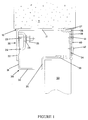
- Figure 1
- is a cross-section through a door frame in accordance with the present invention configured for an inwardly-opening door;
- Figure 2
- is a similar view to Figure 1, showing the same door frame at its maximum extent of adjustment, and
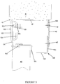
- Figure 3
- is a cross-section through a door frame in accordance with the invention configured for an outwardly-opening door, and showing an alternative embodiment of mounting bracket.
- Referring now to Figure 1, there is shown generally an
opening 10 in awall 11 to which a frame assembly according to the present invention has been fitted. The frame assembly comprises anelongate mounting bracket 20 of generally L-shaped cross-section, aframe member 30 engageable with the mounting bracket, and acapping member 40 which serves to disguise any unsightly gaps between the mounting bracket and the frame member. - As shown, the
mounting bracket 20 has afirst limb 21 adapted to be secured to the opening, for example by bolts or other suitable wall fixings (not shown). Thesecond limb 22 of the mounting bracket is perpendicular to thefirst limb 21 and bears a plurality ofstuds 23 on its internal surface which project in a plane substantially parallel to the plane of thefirst limb 21. Eachstud 23 carries a substantiallyU-shaped clamp 24 which is retained on the stud by a nut andwasher combination - At the extremity of the
first limb 21 of themounting bracket 20, there is abent portion 27 which creates a slight gap between the mounting bracket and thewall 11. The purpose of this is to provide anabutment 28 against which the cappingmember 40 can be braced. The extremity offirst limb 21 is also provided with a plurality ofcapping support brackets 29 to which thecapping member 40 is secured by means of self-tappingscrews 41. - The
frame member 30 comprises amounting portion 31, afirst wall portion 32, astepped portion 35, asecond wall portion 33 and a returnedportion 34. In use, theframe member 30 is oriented so that themounting portion 31 is perpendicular to thefirst limb 21 of themounting bracket 20, and is positioned such that it overlaps thesecond limb 22 on the stud-bearing surface thereof.First wall portion 32 extends parallel tofirst limb 21 of themounting bracket 20 and is spaced apart therefrom. Steppedportion 35 extends a short distance in a direction towards thefirst limb 21 of themounting bracket 20 and serves as a stop or slamming post which limits pivotal movement of thedoor leaf 50. Depending on whether the door has a left- or right-opening leaf,second wall portion 33 of the frame member is adapted to mount either a part of a locking mechanism or the hinges from which thedoor leaf 50 is suspended. Thereturned portion 34 of the frame member extends further in the direction towards thefirst limb 21 of themounting bracket 20, but stops short thereof in order to leave access to thestuds 23 andclamps 24. The returnedportion 34 also serves as a second fixing support forcapping member 40, which is held in place by self-tappingscrews 42. Screw-fixing is the preferred mode of fastening of thecapping member 40 since this results in a rigid assembly. - Figure 1 depicts the frame assembly in the condition of minimum adjustment. In other words, the
frame member 30 is urged as close as possible to thewall 11 before clamping. In the fully-assembled condition as shown, each of the arms of the U-shapedclamp 26 has its end urged against one of either thesecond limb 22 of themounting bracket 20 or mountingportion 31 of theframe member 30. This clamps the frame member to the mounting bracket in a secure manner. Thenut 25 is fully-tightened on thestud 23 using any suitable means such as a socket wrench, prior to fastening of the cappingmember 40 in position. - Figure 2 shows the same frame assembly as Figure 1, but in the condition of maximum adjustment. Here, the
frame member 30 is positioned as far as possible from thewall 11 before clamping, so that there is very little overlap between the mountingportion 31 and thesecond limb 22 of the mountingbracket 20. This condition of maximum adjustment necessitates use of awider capping member 40 and also clamps 24 having a wider separation between their arms. - Typically, the degree of adjustment available on each side of the opening is about 30 mm, giving a total of 60 mm adjustment. This results in considerable versatility since only the capping member and clamps need to be supplied in different sizes. In practice, it makes good sense to use clamps of only two sizes, i.e. small and large, because installation may be rendered unduly complicated by providing a range of intermediate sizes. In these circumstances, clamps having separation distances differing by 15 mm between their arms would be suitable.
- Turning now to Figure 3, here there is shown a frame assembly according to the invention configured for an outwardly-opening door and which includes a modified form of mounting bracket. The frame assembly is depicted in a condition of intermediate adjustment.
- As previously described, the frame assembly comprises an elongate mounting
bracket 120 of generally L-shaped cross-section, aframe member 130 engageable with the mounting bracket, and a cappingmember 40 serving to disguise unsightly gaps between the mounting bracket and the frame member. - The mounting
bracket 120 and cappingmember 40 are similar to those described in relation to Figures 1 and 2 so need not be described in detail again for a complete understanding of the embodiment of Figure 3. - Mounting
bracket 120 has afirst limb 121 adapted to be secured to the opening, for example by bolts or other suitable wall fixings (not shown). Thesecond limb 122 of the mounting bracket is perpendicular to thefirst limb 121 and bears a plurality of studs 123 on its internal surface which project in a plane substantially parallel to the plane of thefirst limb 121. Each stud 123 carries a substantiallyU-shaped clamp 124 which is retained on the stud by a nut andwasher combination - At the extremity of the
first limb 121 of the mountingbracket 120, there is areturn limb 129 to which the cappingmember 40 is fastened by means of self-tappingscrews 41. -
Frame member 130 comprises a mountingportion 131, afirst wall portion 132, a steppedportion 135, asecond wall portion 133 and a returnedportion 134. In use, theframe member 130 is positioned with its mountingportion 131 overlapping thesecond limb 122 on the stud-bearing surface thereof.First wall portion 132 extends parallel tofirst limb 121 of the mountingbracket 120 and is spaced apart therefrom. Steppedportion 135 extends a short distance in a direction away from thefirst limb 121 of the mounting bracket and serves as a stop or slamming post which limits pivotal movement of thedoor leaf 50.First wall portion 132 receives either the hinges from which thedoor leaf 50 is suspended or a part of a locking mechanism, depending on whether the door has a left- or right-opening leaf. The returnedportion 134 extends towards thefirst limb 121 of the mountingbracket 120, but stops short thereof in order to leave access to the studs 123 and clamps 124. By virtue of the fact that the steppedportion 135 extends in the opposite direction compared to steppedportion 35 of Figures 1 and 2, the returnedportion 134 is longer in the frame configured for an outwardly-opening door. Nevertheless, returnedportion 134 still serves as a second fixing support for cappingmember 40. - Although the invention has been particularly described with reference to Figures which show only one edge of an opening and hence only one side of the door frame, it will be understood by persons skilled in the art that a door frame in accordance with the invention will additionally comprise at least a second side and may also include a top portion. Other variations of the invention may be apparent to persons skilled in the art without departing from the scope of the claims which follow.
Claims (14)
- A door frame comprising a mounting bracket (20) adapted to abut in use with at least two sides of a reveal in an opening, a frame member (30) mountable on the mounting bracket (20) and a capping member (40) extending between the mounting bracket (20) and the frame member (30), characterised in that said mounting bracket (20) comprises an elongate metal angle having an L-shaped cross-section a first limb (21) of which is adapted to be secured to the reveal and the second limb (22) of which has a plurality of studs (23) facilitating connection of said mounting bracket (20) to the frame member (30), and in that said frame member (30) comprises a metal section having a mounting portion (31) extending perpendicularly to the first limb (21) of said mounting bracket (20), at least one wall portion (32, 33) extending parallel to said first limb (21) but spaced apart therefrom, and a returned portion (34) extending parallel to said mounting portion (31), said returned portion (34) having access means allowing access to said studs (23), wherein the capping member (40) extends between the extremity of the first limb (21) of said mounting bracket (20) and the returned portion (34) of said frame member (30).
- A door frame as claimed in claim 1 wherein the frame member (30) is substantially U-shaped in cross-section.
- A door frame as claimed in claim 2 wherein the mounting bracket (20) second limb (22) extends beyond the mounting portion (31) of the frame member (30) to serve as a stop for checking pivotal movement of the door.
- A door frame as claimed in any preceding claim wherein the mounting portion (31) and the returned portion (34) of the frame member (30) are of different lengths.
- A door frame as claimed in any preceding claim wherein the frame member (30) is fastened to the mounting bracket (20) by clamps (24) which overlie the mounting portion (31) of the frame member (30) and which are secured to the studs (23) on the mounting bracket (20) by suitable fastening means (25, 26).
- A door frame as claimed in claim 5 wherein the studs (23) are threaded and the fastening means comprise nuts (25).
- A door frame as claimed in claim 5 or claim 6 wherein the clamps (24) are arranged to swivel on the studs (23) between a parking position in which they do not engage the frame member (30) and a clamping position in which they can be fastened to the frame member (30).
- A door frame as claimed in any one of claims 1, 2 and 4 to 7 wherein said wall portion (32, 33) of the frame member (30) is stepped to provide first (32) and second (33) wall portions connected to each other by an intermediate stepped portion (35).
- A door frame as claimed in claim 8 wherein the intermediate stepped portion (35) serves as a stop or slamming post which limits pivotal movement of the door.
- A door frame as claimed in any one of claims 1 to 4 wherein the mounting portion (31) of the frame member (30) is provided with holes or slots to receive the studs (23) of the mounting bracket (20).
- A door frame as claimed in claim 10 wherein the studs (23) are formed with an enlarged head portion which is loosely held behind a retaining bracket to allow sliding adjustment of the position of the studs (23).
- A door frame as claimed in any preceding claim wherein the extremity of the first limb (21) of the mounting bracket (20) is bent away from the wall to provide an abutment against which the capping member (40) is braced.
- A door frame as claimed in any preceding claim wherein the first limb (21) of the mounting bracket (20) has a plurality of capping support brackets.
- A door frame as claimed in any one of claims 1 to 12 wherein there is a return limb at the extremity of the first limb (21) of the mounting bracket (20) for mounting the capping member (40).
Applications Claiming Priority (2)
| Application Number | Priority Date | Filing Date | Title |
|---|---|---|---|
| GB9400489A GB2285827A (en) | 1994-01-12 | 1994-01-12 | Door frame |
| GB9400489 | 1994-01-12 |
Publications (2)
| Publication Number | Publication Date |
|---|---|
| EP0663506A2 true EP0663506A2 (en) | 1995-07-19 |
| EP0663506A3 EP0663506A3 (en) | 1995-10-11 |
Family
ID=10748681
Family Applications (1)
| Application Number | Title | Priority Date | Filing Date |
|---|---|---|---|
| EP94308992A Ceased EP0663506A3 (en) | 1994-01-12 | 1994-12-02 | Door frame. |
Country Status (2)
| Country | Link |
|---|---|
| EP (1) | EP0663506A3 (en) |
| GB (1) | GB2285827A (en) |
Cited By (1)
| Publication number | Priority date | Publication date | Assignee | Title |
|---|---|---|---|---|
| FR2960901A1 (en) * | 2010-06-08 | 2011-12-09 | Baumert Technologies | DOOR BLOCK STRUCTURE |
Families Citing this family (1)
| Publication number | Priority date | Publication date | Assignee | Title |
|---|---|---|---|---|
| GB9421200D0 (en) * | 1994-10-20 | 1994-12-07 | Sapa Holdings Ltd | Improvements in or relating to door frame structures |
Family Cites Families (4)
| Publication number | Priority date | Publication date | Assignee | Title |
|---|---|---|---|---|
| US4179849A (en) * | 1978-03-02 | 1979-12-25 | Kueffner Products, Inc. | Door frame assembly |
| SE8104185L (en) * | 1981-07-06 | 1983-01-07 | Hellbergs Ind Ab | FRAME |
| US4878325A (en) * | 1987-02-25 | 1989-11-07 | Tuyl James E Van | Two piece adjustable, reusable metal door frame |
| GB8710118D0 (en) * | 1987-04-29 | 1987-06-03 | Huelin Kirk John | Door frame structure |
-
1994
- 1994-01-12 GB GB9400489A patent/GB2285827A/en not_active Withdrawn
- 1994-12-02 EP EP94308992A patent/EP0663506A3/en not_active Ceased
Cited By (4)
| Publication number | Priority date | Publication date | Assignee | Title |
|---|---|---|---|---|
| FR2960901A1 (en) * | 2010-06-08 | 2011-12-09 | Baumert Technologies | DOOR BLOCK STRUCTURE |
| WO2011154618A1 (en) * | 2010-06-08 | 2011-12-15 | BAUMERT TECHNOLOGIES (Société par Actions Simplifiée Unipersonnelle) | Prehung door unit structure |
| CN102947529A (en) * | 2010-06-08 | 2013-02-27 | 博脉特(有限公司) | Prehung door unit structure |
| US8733025B2 (en) | 2010-06-08 | 2014-05-27 | Baumert | Prehung door unit structure |
Also Published As
| Publication number | Publication date |
|---|---|
| EP0663506A3 (en) | 1995-10-11 |
| GB2285827A (en) | 1995-07-26 |
| GB9400489D0 (en) | 1994-03-09 |
Similar Documents
| Publication | Publication Date | Title |
|---|---|---|
| US6286274B1 (en) | Clip mounting system for door frame | |
| US5566995A (en) | Door security system | |
| US4223494A (en) | Doorframe assembly for partition wall construction | |
| US5070650A (en) | Door jamb reinforcing apparatus | |
| US3571995A (en) | Adjustable doorframe | |
| US4179849A (en) | Door frame assembly | |
| US5581948A (en) | Kick resistant door assembly | |
| US5722206A (en) | Flexible storm resistant system | |
| US20020043033A1 (en) | Access door mounted on pivoting frame | |
| US4878325A (en) | Two piece adjustable, reusable metal door frame | |
| US4699289A (en) | Structure of switch box | |
| US5661935A (en) | Storm panel track | |
| US7340866B1 (en) | Wall adapter | |
| US5904014A (en) | Fireproof trim for a landing door for a lift | |
| US5701813A (en) | Pet door for screen applications | |
| US5263295A (en) | Suspended security ceiling system | |
| AU2003203700A1 (en) | Device for holding panels and separating element | |
| US4872717A (en) | Strike plate reinforcing device | |
| US7165793B2 (en) | Door jamb security plate | |
| GB2285827A (en) | Door frame | |
| US6293060B1 (en) | Door frame with securing and sealing flange | |
| US7516581B2 (en) | Split door frame assembly | |
| US6314616B1 (en) | Cabinet door securement system for a face frame cabinet | |
| US5199235A (en) | Clean room wall system | |
| US20040103587A1 (en) | Access door |
Legal Events
| Date | Code | Title | Description |
|---|---|---|---|
| PUAI | Public reference made under article 153(3) epc to a published international application that has entered the european phase |
Free format text: ORIGINAL CODE: 0009012 |
|
| AK | Designated contracting states |
Kind code of ref document: A2 Designated state(s): BE DE FR GB LU NL |
|
| PUAL | Search report despatched |
Free format text: ORIGINAL CODE: 0009013 |
|
| AK | Designated contracting states |
Kind code of ref document: A3 Designated state(s): BE DE FR GB LU NL |
|
| 17P | Request for examination filed |
Effective date: 19960410 |
|
| GRAG | Despatch of communication of intention to grant |
Free format text: ORIGINAL CODE: EPIDOS AGRA |
|
| 17Q | First examination report despatched |
Effective date: 19970613 |
|
| STAA | Information on the status of an ep patent application or granted ep patent |
Free format text: STATUS: THE APPLICATION HAS BEEN REFUSED |
|
| 18R | Application refused |
Effective date: 19971201 |