EP0662203B1 - Manual transmission shifter - Google Patents
Manual transmission shifter Download PDFInfo
- Publication number
- EP0662203B1 EP0662203B1 EP93922137A EP93922137A EP0662203B1 EP 0662203 B1 EP0662203 B1 EP 0662203B1 EP 93922137 A EP93922137 A EP 93922137A EP 93922137 A EP93922137 A EP 93922137A EP 0662203 B1 EP0662203 B1 EP 0662203B1
- Authority
- EP
- European Patent Office
- Prior art keywords
- axis
- shift lever
- cable
- bellcrank
- shifter
- Prior art date
- Legal status (The legal status is an assumption and is not a legal conclusion. Google has not performed a legal analysis and makes no representation as to the accuracy of the status listed.)
- Expired - Lifetime
Links
- 230000005540 biological transmission Effects 0.000 title claims abstract description 22
- 230000000717 retained effect Effects 0.000 claims description 2
- 238000005452 bending Methods 0.000 description 2
- 239000002184 metal Substances 0.000 description 2
- 239000004033 plastic Substances 0.000 description 2
- 238000005728 strengthening Methods 0.000 description 2
- 229910000831 Steel Inorganic materials 0.000 description 1
- 238000006243 chemical reaction Methods 0.000 description 1
- 238000010276 construction Methods 0.000 description 1
- 230000013011 mating Effects 0.000 description 1
- 230000004048 modification Effects 0.000 description 1
- 238000012986 modification Methods 0.000 description 1
- 239000002991 molded plastic Substances 0.000 description 1
- 230000007935 neutral effect Effects 0.000 description 1
- 125000006850 spacer group Chemical group 0.000 description 1
- 239000010959 steel Substances 0.000 description 1
Images

Classifications
-
- F—MECHANICAL ENGINEERING; LIGHTING; HEATING; WEAPONS; BLASTING
- F16—ENGINEERING ELEMENTS AND UNITS; GENERAL MEASURES FOR PRODUCING AND MAINTAINING EFFECTIVE FUNCTIONING OF MACHINES OR INSTALLATIONS; THERMAL INSULATION IN GENERAL
- F16H—GEARING
- F16H61/00—Control functions within control units of change-speed- or reversing-gearings for conveying rotary motion ; Control of exclusively fluid gearing, friction gearing, gearings with endless flexible members or other particular types of gearing
- F16H61/26—Generation or transmission of movements for final actuating mechanisms
- F16H61/36—Generation or transmission of movements for final actuating mechanisms with at least one movement being transmitted by a cable
-
- Y—GENERAL TAGGING OF NEW TECHNOLOGICAL DEVELOPMENTS; GENERAL TAGGING OF CROSS-SECTIONAL TECHNOLOGIES SPANNING OVER SEVERAL SECTIONS OF THE IPC; TECHNICAL SUBJECTS COVERED BY FORMER USPC CROSS-REFERENCE ART COLLECTIONS [XRACs] AND DIGESTS
- Y10—TECHNICAL SUBJECTS COVERED BY FORMER USPC
- Y10T—TECHNICAL SUBJECTS COVERED BY FORMER US CLASSIFICATION
- Y10T74/00—Machine element or mechanism
- Y10T74/20—Control lever and linkage systems
- Y10T74/20012—Multiple controlled elements
- Y10T74/20018—Transmission control
- Y10T74/20049—Transmission controlled by flexible cable
-
- Y—GENERAL TAGGING OF NEW TECHNOLOGICAL DEVELOPMENTS; GENERAL TAGGING OF CROSS-SECTIONAL TECHNOLOGIES SPANNING OVER SEVERAL SECTIONS OF THE IPC; TECHNICAL SUBJECTS COVERED BY FORMER USPC CROSS-REFERENCE ART COLLECTIONS [XRACs] AND DIGESTS
- Y10—TECHNICAL SUBJECTS COVERED BY FORMER USPC
- Y10T—TECHNICAL SUBJECTS COVERED BY FORMER US CLASSIFICATION
- Y10T74/00—Machine element or mechanism
- Y10T74/20—Control lever and linkage systems
- Y10T74/20012—Multiple controlled elements
- Y10T74/20018—Transmission control
- Y10T74/2014—Manually operated selector [e.g., remotely controlled device, lever, push button, rotary dial, etc.]
- Y10T74/20159—Control lever movable through plural planes
-
- Y—GENERAL TAGGING OF NEW TECHNOLOGICAL DEVELOPMENTS; GENERAL TAGGING OF CROSS-SECTIONAL TECHNOLOGIES SPANNING OVER SEVERAL SECTIONS OF THE IPC; TECHNICAL SUBJECTS COVERED BY FORMER USPC CROSS-REFERENCE ART COLLECTIONS [XRACs] AND DIGESTS
- Y10—TECHNICAL SUBJECTS COVERED BY FORMER USPC
- Y10T—TECHNICAL SUBJECTS COVERED BY FORMER US CLASSIFICATION
- Y10T74/00—Machine element or mechanism
- Y10T74/20—Control lever and linkage systems
- Y10T74/20012—Multiple controlled elements
- Y10T74/20201—Control moves in two planes
-
- Y—GENERAL TAGGING OF NEW TECHNOLOGICAL DEVELOPMENTS; GENERAL TAGGING OF CROSS-SECTIONAL TECHNOLOGIES SPANNING OVER SEVERAL SECTIONS OF THE IPC; TECHNICAL SUBJECTS COVERED BY FORMER USPC CROSS-REFERENCE ART COLLECTIONS [XRACs] AND DIGESTS
- Y10—TECHNICAL SUBJECTS COVERED BY FORMER USPC
- Y10T—TECHNICAL SUBJECTS COVERED BY FORMER US CLASSIFICATION
- Y10T74/00—Machine element or mechanism
- Y10T74/20—Control lever and linkage systems
- Y10T74/20396—Hand operated
- Y10T74/20402—Flexible transmitter [e.g., Bowden cable]
-
- Y—GENERAL TAGGING OF NEW TECHNOLOGICAL DEVELOPMENTS; GENERAL TAGGING OF CROSS-SECTIONAL TECHNOLOGIES SPANNING OVER SEVERAL SECTIONS OF THE IPC; TECHNICAL SUBJECTS COVERED BY FORMER USPC CROSS-REFERENCE ART COLLECTIONS [XRACs] AND DIGESTS
- Y10—TECHNICAL SUBJECTS COVERED BY FORMER USPC
- Y10T—TECHNICAL SUBJECTS COVERED BY FORMER US CLASSIFICATION
- Y10T74/00—Machine element or mechanism
- Y10T74/20—Control lever and linkage systems
- Y10T74/20396—Hand operated
- Y10T74/20402—Flexible transmitter [e.g., Bowden cable]
- Y10T74/2042—Flexible transmitter [e.g., Bowden cable] and hand operator
Definitions
- This invention relates generally to manual transmission shifters and, more particularly, to a manual transmission shifter which operates two control cables that move independently of each other.
- Shifters for operating manual transmissions have been in existence for decades. These shifters have taken many forms and have been located in many different positions on a vehicle. Some shifters are mounted directly atop the transmission and control the transmissions by directly moving levers.
- DE-U-90 02 840 (on which the two-part form of independent claim 1 is based) there is disclosed a shifter which controls two transmission control cables by moving the shift lever about orthogonal axes to operate one cable without moving the non-operated cable.
- the lever is connected by linkages to two shift cables which are located outside the shifter base.
- This shifter arrangement requires bending of the cable sheaths to achieve side-by-side arrangement of the cables for entraining through the vehicle to the transmission. This arrangement would incur excessive friction forces due to bending of the cable sheaths.
- a shifter for operating a pair of transmission control cables, comprising a base, a shift lever, a lever support mounted on the base for relative pivotal movement about a first axis and mounting said lever for relative pivotal movement about a second intersecting orthogonal axis, a cable control member mounted for pivotal movement with the lever support about the first axis and having its lower end connected directly to one of the control cables, a bellcrank pivotally mounted on the base, and a control arm pivotally connecting one leg of the bellcrank to the shift lever for movement of the bellcrank by movement of the shift lever about said second axis, the other leg of the bellcrank being operatively connected to the other control cable adjacent the base, whereby movement of the shift lever about the first axis operates said one cable without moving said other cable, characterized in that the base includes a housing and the lever support is mounted at spaced points on the housing, and that the cable control member is connected directly to said one control cable within the housing directly beneath the shift lever and has
- the bellcrank pivotal mounting on the base is on a third axis that is coplanar with the orthogonal axes, which enables operation of the one cable by movement of the shift lever and cross about the second axis without moving the other cable.
- this invention features a control arm connected to the bellcrank one leg via a pivotal connection which permits both universal and sliding movement of the control arm relative to the bellcrank one arm.
- the pivotal connection to the bellcrank one leg is on the first axis and comprises a slot in the bellcrank one arm, a shoe slidably retained in the slot, and a universal connection comprising a ball on the control arm and a socket on the shoe which receives the ball.
- the cross has a body with the ends of both axles extending therefrom
- the shift lever bracket includes a pair of spaced legs pivotally attached to the ends of the second axle
- the cable control member includes a pair of spaced arms pivotally attached to the second axle outwardly of the shift lever bracket legs.
- a shifter 10 generally comprises a shift lever 12 mounted on a base 14 that operates a pair of push-pull, or Bowden cables 16 and 18.
- Lever 12 is pivoted about intersecting, orthogonal axes X and Y to reciprocate cable wires 16a and 18a within sheaths 16b and 18b longitudinally of base 14 to control a manual transmission (not shown) in a conventional and well-known manner.
- Shifter base 14 includes a lower housing 20 that has an upper wall 22 connecting a rear end wall 24 and a front end wall 26.
- An apertured horizontal mounting flange 28 extends rearwardly from rear end wall 24.
- a boxed mounting flange 30 extends forwardly from front end wall 26 which includes a rectangular opening 31 through which cable wire 16a extends.
- Flange 30 includes an apertured bottom wall 32 and upstanding front walls 34 and 36 connected by strengthening ribs 38, 40 and 42. Strengthening ribs 44 and 46 extend between rear end wall 24 and mounting flange 28.
- Front walls 34 and 36 include keyhole-shaped slots 48 and 50 which mount end fittings 16c and 18c of cable sheaths 16b and 18b, respectively.
- Plastic mounting grommets 52 are inserted into the apertures in mounting flange 28 and flange floor 32.
- Upper housing 54 is mounted atop lower housing 20 by bolting flange 56 to upper wall 22. Both lower and upper housings 20 and 54 are illustrated as separate metal parts but can be formed as a single cast metal or molded plastic housing. Upper housing 54 includes front and rear walls 58 and 60 and side walls 62 and 64 which extend upwardly from flange 56 and define a central opening 66 which mates with a similar opening 68 in lower housing upper wall 22.
- Side wall 64 includes a full-length notch 70, while both side walls 62 and 64 include aligned holes 72a and 72b.
- a headed mounting pin or axle 74 is received through aligned holes 72a and 72b and is secured by a circlip 76.
- Pin 74 extends through a bore 78 in a shift lever support or cross 80 to mount cross 80 to upper housing 54 for pivotal movement about axis X which pin 74 defines.
- Cross 80 also includes another bore 82 which is orthogonal to and intersects bore 78.
- Bore 82 receives a pin 84 at its rear end and a headed and knurled stud 86 at its front end which together constitute another axle that defines axis Y .
- Stud 86 extends through an aperture 88a in a depending flange 90a of a mounting bracket 90 and through a spacer 85 into bore 82.
- pin 84 extends through an aligned aperture 88b formed in another depending leg 90b of mounting bracket 90 and into bore 82.
- Shift lever 12 is preferably steel and is welded, screwed or otherwise affixed to mounting bracket 90 for pivotal movement about axis X of pin 84 and stud 86 relative to cross 80. At its upper end, shift lever 12 mounts a knob 92.
- a control arm 94 is secured to pin 84 for movement therewith and mounts a spherical ball 96 on one end thereof.
- Ball 96 is located on axis X and is received in a mating socket of a plastic rectangular slide block 98.
- Slide block 98 is slidingly received in an elongated, flanged rectangular slot 100 in a leg 102 of a bellcrank 104.
- a pivot pin 106 in the form of a flanged stud, is rigidly mounted on the corner of bellcrank 104.
- Stud 106 extends through the bore of a boss 108 formed on upper housing 54 adjacent rear wall 60 and is secured by a circlip 110.
- Stud 106 defines an axis Z about which bellcrank 104 pivots and that is coplanar with axis X .
- the other leg 112 of bellcrank 104 mounts a stud 114 that pivotally mounts end fitting 116 on cable wire 18a. Pivotal movement of bellcrank 104 about axis Z moves bellcrank leg 112 longitudinally and reciprocates cable wire 18a through cable sheath 18b.
- a cable control member or link 120 comprises a Y -shaped body 122 flanked by a pair of angled flanges 124 and 126. Aligned holes 128a and 128b are formed in flanges 124 and 126 to mount the flanges to pin 84 and stud 86 outboard of shift lever mounting bracket flanges 90a and 90b.
- Link 120 is pivotable about axis Y of pin 84 and stud 86 relative to cross 80 and is independent of shift lever mounting bracket 90.
- link 120 carries a stud 130 that pivotally mounts end fitting 132 on cable wire 16a. Pivotal movement of link 120 about axis X moves stud 130 and end fitting 132 longitudinally and reciprocates wire 16a through cable sheath 16b.
- This invention enables each of shifter cable wires 16a and 18a to be moved completely independently of any movement of the other wire. This occurs because both shift lever 12, via its mounting bracket 90, and link 120 are independently pivotable about axis Y relative to cross 80, and are movable with cross 80 as a unit about axis X . Since ball 96 is located on axis X , and block 98 slides in slot 100, movement of shift lever 12 about axis X will shift cable wire 16a without any lateral movement of the end of cable wire 18a. Also, since link 120 is independent of shift lever 12, movement of the shift lever 12 about axis Y will shift cable wire 18a without any movement of cable wire 16a.
- shifter 10 Operation of shifter 10 is as follows. When shifter 10 is in a transmission neutral position, lever 12 is centered longitudinally of base 14, as is conventional. To select a gear, lever 12 is moved laterally of base 14 by pivoting it about the Y axis. This action pivots control arm 94, lifting or lowering bellcrank leg 102, which pivots bellcrank 104 about axis Z . This moves bellcrank leg 112 longitudinally, which reciprocates cable wire 18a. The pivoting of ball 96 in slide 98 and the sliding of slide 98 in slot 100 permit this conversion of lateral lever movement to longitudinal cable wire movement. Since link 120 is independently mounted on axis Y , it and the end of cable wire 16a experience no lateral movement during this shifting of cable wire 18a.
- the shifting movement of shifter 10 is completed by moving lever 12 longitudinally of base 14 to select a gear.
- ball 96 which connects lever 12 to bellcrank 104 via slide block 98, is located on axis X , this longitudinal movement of lever 12 to shift wire 16a does not move the end of wire 18a.
Landscapes
- Engineering & Computer Science (AREA)
- General Engineering & Computer Science (AREA)
- Mechanical Engineering (AREA)
- Gear-Shifting Mechanisms (AREA)
- Arrangement Or Mounting Of Control Devices For Change-Speed Gearing (AREA)
Abstract
Description
- This invention relates generally to manual transmission shifters and, more particularly, to a manual transmission shifter which operates two control cables that move independently of each other.
- Shifters for operating manual transmissions have been in existence for decades. These shifters have taken many forms and have been located in many different positions on a vehicle. Some shifters are mounted directly atop the transmission and control the transmissions by directly moving levers.
- Other shifters have been mounted on the vehicle's steering column remote from the transmission and operate the transmission by a series of articulated linkages. Currently, most shifters are floor-mounted at a location remote from the transmission. Recently, vehicles have become smaller, more compact and burdened with under-floor pollution control equipment. This has complicated the use of articulated linkages, because there is no longer an uncluttered straight path between the shifter and the transmission.
- Accordingly, so-called "cable shifters" have been developed. These shifters manipulate two Bowden, or push-pull, cables to operate the transmission. An early example of a cable shifter of this type is shown in US-A-4,143,560 which features a ball shifter which operates a pair of transmission control cables by moving a shift lever about intersecting orthogonal shift lever axes. One of the control cables is operated directly by a lower extension of the shift lever when the lever is moved about one of the shift lever axes. The other cable is indirectly operated by a bellcrank which is pivoted by movement of the shift lever about the other shift lever axis.
- One problem encountered with this type of shifter is lateral flexing movement of the directly-operated cable when the other cable is operated by the shift lever. In an attempt to overcome this problem, a depending pivoted link was interposed between the shift lever and the directly-operated control cable. This arrangement is disclosed in US-A-4,693,135 which features a similar ball shifter which operates two transmission control cables by moving a shift lever about intersecting orthogonal axes. This arrangement reduces the unwanted lateral flexing movement of the cable. However, this movement is not eliminated and the added pivot point introduces a point of potential looseness, or "play" in the linkage.
- In DE-U-90 02 840 (on which the two-part form of independent claim 1 is based) there is disclosed a shifter which controls two transmission control cables by moving the shift lever about orthogonal axes to operate one cable without moving the non-operated cable. In this known shifter the lever is connected by linkages to two shift cables which are located outside the shifter base. This shifter arrangement requires bending of the cable sheaths to achieve side-by-side arrangement of the cables for entraining through the vehicle to the transmission. This arrangement would incur excessive friction forces due to bending of the cable sheaths.
- There is provided in accordance with the invention a shifter for operating a pair of transmission control cables, comprising a base, a shift lever, a lever support mounted on the base for relative pivotal movement about a first axis and mounting said lever for relative pivotal movement about a second intersecting orthogonal axis, a cable control member mounted for pivotal movement with the lever support about the first axis and having its lower end connected directly to one of the control cables, a bellcrank pivotally mounted on the base, and a control arm pivotally connecting one leg of the bellcrank to the shift lever for movement of the bellcrank by movement of the shift lever about said second axis, the other leg of the bellcrank being operatively connected to the other control cable adjacent the base, whereby movement of the shift lever about the first axis operates said one cable without moving said other cable, characterized in that the base includes a housing and the lever support is mounted at spaced points on the housing, and that the cable control member is connected directly to said one control cable within the housing directly beneath the shift lever and has a pair of spaced flanges pivoted at their upper ends directly to said lever support to enable pivotal movement of the control member relative to the lever support about said second axis, while enabling said pivotal movement of the cable control member with the lever support about the first axis.
- Preferably, the bellcrank pivotal mounting on the base is on a third axis that is coplanar with the orthogonal axes, which enables operation of the one cable by movement of the shift lever and cross about the second axis without moving the other cable.
- In an advantageous one embodiment, this invention features a control arm connected to the bellcrank one leg via a pivotal connection which permits both universal and sliding movement of the control arm relative to the bellcrank one arm. Preferably, the pivotal connection to the bellcrank one leg is on the first axis and comprises a slot in the bellcrank one arm, a shoe slidably retained in the slot, and a universal connection comprising a ball on the control arm and a socket on the shoe which receives the ball.
- Preferably, the cross has a body with the ends of both axles extending therefrom, the shift lever bracket includes a pair of spaced legs pivotally attached to the ends of the second axle, and the cable control member includes a pair of spaced arms pivotally attached to the second axle outwardly of the shift lever bracket legs.
- These and further features of this invention will become more readily apparent upon reference to the following detailed description of a preferred embodiment, as illustrated in the accompanying drawings, in which:
-
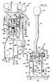
- Fig. 1 is an exploded perspective view of a manual transmission shifter, according to this invention;
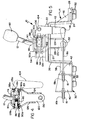
- Fig. 2 is a sectional plan view of the shifter of Fig. 1, taken along line 2 - 2 of Fig. 3;
- Fig. 3 is a sectional end view of the shifter of Fig. 1, taken along line 3 - 3 of Fig. 2;
- Fig. 4 is a detail view of a portion of the shifter of Fig. 1, partially broken away to show details of construction; and
- Fig. 5 is a side elevational view of the shifter of Fig. 1.
- Referring now to the drawings, a shifter 10 generally comprises a
shift lever 12 mounted on abase 14 that operates a pair of push-pull, or Bowdencables Lever 12 is pivoted about intersecting, orthogonal axes X and Y to reciprocatecable wires sheaths base 14 to control a manual transmission (not shown) in a conventional and well-known manner. - Shifter
base 14 includes alower housing 20 that has anupper wall 22 connecting arear end wall 24 and afront end wall 26. An aperturedhorizontal mounting flange 28 extends rearwardly fromrear end wall 24. A boxedmounting flange 30 extends forwardly fromfront end wall 26 which includes arectangular opening 31 through whichcable wire 16a extends.Flange 30 includes an apertured bottom wall 32 and upstandingfront walls ribs rear end wall 24 and mountingflange 28. -
Front walls shaped slots end fittings cable sheaths Plastic mounting grommets 52 are inserted into the apertures in mountingflange 28 and flange floor 32. - An
upper housing 54 is mounted atoplower housing 20 by boltingflange 56 toupper wall 22. Both lower andupper housings Upper housing 54 includes front andrear walls side walls flange 56 and define acentral opening 66 which mates with asimilar opening 68 in lower housingupper wall 22. -
Side wall 64 includes a full-length notch 70, while bothside walls holes axle 74 is received through alignedholes circlip 76.Pin 74 extends through abore 78 in a shift lever support or cross 80 to mountcross 80 toupper housing 54 for pivotal movement about axis X whichpin 74 defines. - Cross 80 also includes another
bore 82 which is orthogonal to and intersects bore 78. Bore 82 receives apin 84 at its rear end and a headed andknurled stud 86 at its front end which together constitute another axle that defines axis Y.Stud 86 extends through anaperture 88a in a dependingflange 90a of amounting bracket 90 and through aspacer 85 intobore 82. Similarly,pin 84 extends through an alignedaperture 88b formed in another dependingleg 90b ofmounting bracket 90 and intobore 82.Shift lever 12 is preferably steel and is welded, screwed or otherwise affixed to mountingbracket 90 for pivotal movement about axis X ofpin 84 andstud 86 relative tocross 80. At its upper end, shift lever 12 mounts aknob 92. - As best seen in Figs. 2 and 3, a
control arm 94 is secured topin 84 for movement therewith and mounts aspherical ball 96 on one end thereof.Ball 96 is located on axis X and is received in a mating socket of a plasticrectangular slide block 98.Slide block 98 is slidingly received in an elongated, flangedrectangular slot 100 in aleg 102 of abellcrank 104. - A
pivot pin 106, in the form of a flanged stud, is rigidly mounted on the corner ofbellcrank 104.Stud 106 extends through the bore of aboss 108 formed onupper housing 54 adjacentrear wall 60 and is secured by acirclip 110.Stud 106 defines an axis Z about whichbellcrank 104 pivots and that is coplanar with axis X. Theother leg 112 ofbellcrank 104 mounts astud 114 that pivotally mounts end fitting 116 oncable wire 18a. Pivotal movement ofbellcrank 104 about axis Z movesbellcrank leg 112 longitudinally and reciprocatescable wire 18a throughcable sheath 18b. - A cable control member or link 120 comprises a Y-shaped body 122 flanked by a pair of
angled flanges holes flanges stud 86 outboard of shift lever mountingbracket flanges Link 120 is pivotable about axis Y ofpin 84 andstud 86 relative to cross 80 and is independent of shiftlever mounting bracket 90. At its lower end, link 120 carries astud 130 that pivotally mounts end fitting 132 oncable wire 16a. Pivotal movement oflink 120 about axis X movesstud 130 and end fitting 132 longitudinally and reciprocateswire 16a throughcable sheath 16b. - This invention enables each of
shifter cable wires shift lever 12, via its mountingbracket 90, and link 120 are independently pivotable about axis Y relative to cross 80, and are movable withcross 80 as a unit about axis X. Sinceball 96 is located on axis X, and block 98 slides inslot 100, movement ofshift lever 12 about axis X will shiftcable wire 16a without any lateral movement of the end ofcable wire 18a. Also, sincelink 120 is independent ofshift lever 12, movement of theshift lever 12 about axis Y will shiftcable wire 18a without any movement ofcable wire 16a. - Operation of shifter 10 is as follows. When shifter 10 is in a transmission neutral position,
lever 12 is centered longitudinally ofbase 14, as is conventional. To select a gear,lever 12 is moved laterally ofbase 14 by pivoting it about the Y axis. This action pivotscontrol arm 94, lifting or loweringbellcrank leg 102, which pivotsbellcrank 104 about axis Z. This movesbellcrank leg 112 longitudinally, which reciprocatescable wire 18a. The pivoting ofball 96 inslide 98 and the sliding ofslide 98 inslot 100 permit this conversion of lateral lever movement to longitudinal cable wire movement. Sincelink 120 is independently mounted on axis Y, it and the end ofcable wire 16a experience no lateral movement during this shifting ofcable wire 18a. - The shifting movement of shifter 10 is completed by moving
lever 12 longitudinally ofbase 14 to select a gear. This pivotslever 12, cross 80 and link 120 as a unit about axis X to movestud 130 and end fitting 132 longitudinally ofbase 14, reciprocatingcable wire 16a withinsheath 16b. Sinceball 96, which connectslever 12 to bellcrank 104 viaslide block 98, is located on axis X, this longitudinal movement oflever 12 to shiftwire 16a does not move the end ofwire 18a. - While only a preferred embodiment has been illustrated and described, obvious modifications thereof are contemplated within the scope of this invention and the following claims.
Claims (7)
- A shifter (10) for operating a pair of transmission control cables (16, 18), comprisinga base (14),a shift lever (12),a lever support (80) mounted on the base (14) for relative pivotal movement about a first axis (X) and mounting said lever (12) for relative pivotal movement about a second intersecting orthogonal axis (Y),a cable control member (120) mounted for pivotal movement with the lever support (80) about the first axis (X) and having its lower end connected directly to one of the control cables (16),a bellcrank (104) pivotally mounted on the base (14), anda control arm (94) pivotally connecting one leg (102) of the bellcrank (104) to the shift lever (12) for movement of the bellcrank (104) by movement of the shift lever (12) about said second axis (Y),the other leg (112) of the bellcrank (104) being operatively connected to the other control cable (18) adjacent the base (14), whereby movement of the shift lever (12) about the first axis (X) operates said one cable (16) without moving said other cable (18),characterized in that the base (14) includes a housing (20, 54) and the lever support (80) is mounted at spaced points (72a, 72b) on the housing (54), and that the cable control member (120) is connected directly to said one control cable (16) within the housing (20) directly beneath the shift lever (12) and has a pair of spaced flanges (124, 126) pivoted at their upper ends (128a, 128b) directly to said lever support (80) to enable pivotal movement of the control member (120) relative to the lever support (80) about said second axis (Y), while enabling said pivotal movement of the cable control member (120) with the lever support (80) about the first axis (X).
- The shifter (10) of claim 1, wherein the bellcrank pivotal mounting (106) on the base (14) is located on a third axis (Z) that is coplanar with the orthogonal axes (X and Y).
- The shifter (10) of claim 2, wherein the control arm (94) has a pivotal connection (96, 98, 100) to the bellcrank one leg (102) which permits both universal and sliding movement of the control arm (94) relative to the bellcrank one leg (102).
- The shifter (10) of claim 3, wherein the control arm pivotal connection (96, 98, 100) to the bellcrank one leg (102) is located on the first axis (X).
- The shifter (10) of claim 4, wherein the pivotal connection (96, 98, 100) comprises a slot (100) in the bellcrank one leg (102), a shoe (98) slidably retained in the slot (100), and a universal connection (96) mounting the control arm (94) to the shoe (98).
- The shifter (10) of claim 5, wherein the universal connection (96, 98) comprises a ball (96) on the control arm (94) and a socket on the shoe (98) which receives the ball (96).
- The shifter (10) of claim 6, wherein the shift lever (12) is mounted on a bracket (90) having a pair of spaced flanges (90a, 90b) mounting the shift lever (12) on the lever support (80) for relative pivotal movement about the second axis (Y) and for movement therewith about the first axis (X).
Applications Claiming Priority (3)
| Application Number | Priority Date | Filing Date | Title |
|---|---|---|---|
| US07/950,462 US5287743A (en) | 1992-09-24 | 1992-09-24 | Manual transmission shifter |
| US950462 | 1992-09-24 | ||
| PCT/US1993/008171 WO1994007059A1 (en) | 1992-09-24 | 1993-08-30 | Manual transmission shifter |
Publications (2)
| Publication Number | Publication Date |
|---|---|
| EP0662203A1 EP0662203A1 (en) | 1995-07-12 |
| EP0662203B1 true EP0662203B1 (en) | 1996-09-25 |
Family
ID=25490462
Family Applications (1)
| Application Number | Title | Priority Date | Filing Date |
|---|---|---|---|
| EP93922137A Expired - Lifetime EP0662203B1 (en) | 1992-09-24 | 1993-08-30 | Manual transmission shifter |
Country Status (4)
| Country | Link |
|---|---|
| US (1) | US5287743A (en) |
| EP (1) | EP0662203B1 (en) |
| DE (1) | DE69305086T2 (en) |
| WO (1) | WO1994007059A1 (en) |
Cited By (2)
| Publication number | Priority date | Publication date | Assignee | Title |
|---|---|---|---|---|
| DE19716992C1 (en) * | 1997-04-23 | 1998-11-19 | United Parts Fhs Automobil Sys | Vehicle gearbox shaft plastics mounting bush |
| DE112008001395T5 (en) | 2007-05-30 | 2010-04-22 | Kongsberg Automotive Ab | Gear shift system for operating a pair of transmission cables |
Families Citing this family (30)
| Publication number | Priority date | Publication date | Assignee | Title |
|---|---|---|---|---|
| BR7401842U (en) * | 1994-10-19 | 1995-03-21 | Paolo Paparoni | Arrangement introduced in articulation mechanism for automotive gear lever with cable drive. |
| IT1276394B1 (en) * | 1995-06-16 | 1997-10-31 | Roltra Morse Spa | COMMAND DEVICE FOR A VEHICLE SPEED CHANGE |
| IT1276393B1 (en) * | 1995-06-16 | 1997-10-31 | Roltra Morse Spa | COMMAND DEVICE FOR A VEHICLE SPEED CHANGE |
| IT1276419B1 (en) * | 1995-06-16 | 1997-10-31 | Roltra Morse Spa | COMMAND DEVICE FOR A VEHICLE SPEED CHANGE |
| IT1276392B1 (en) * | 1995-06-16 | 1997-10-31 | Roltra Morse Spa | COMMAND DEVICE FOR A VEHICLE SPEED CHANGE |
| IT1276396B1 (en) * | 1995-06-16 | 1997-10-31 | Roltra Morse Spa | COMMAND DEVICE FOR A VEHICLE SPEED CHANGE |
| US6286385B1 (en) | 1997-12-02 | 2001-09-11 | Kabushiki Kaisha Tokai-Rika-Denki-Seisakusho | Shift lever device |
| US5845536A (en) * | 1997-03-21 | 1998-12-08 | Saturn Corporation | Transmission shift control mechanism |
| JP3167958B2 (en) * | 1997-05-08 | 2001-05-21 | コナミ株式会社 | Multi-directional switching operation device |
| DE19817166B4 (en) * | 1998-04-17 | 2008-01-31 | Fico Triad S.A., Rubi | lever element |
| JP4143213B2 (en) * | 1999-04-02 | 2008-09-03 | 株式会社アツミテック | Speed change operation device for vehicle |
| US6539822B1 (en) * | 2000-08-09 | 2003-04-01 | Trw Inc. | Transmission shifter assembly with indicator |
| JP3611111B2 (en) * | 2001-04-17 | 2005-01-19 | 川崎重工業株式会社 | Shift lever device for vehicle |
| US6722224B2 (en) * | 2002-01-07 | 2004-04-20 | Husco International, Inc. | Dual axis joystick for operating hydraulic valves |
| US20030213326A1 (en) * | 2002-05-14 | 2003-11-20 | Fett Brian W. | Cable-operated transmission shifters |
| KR20040038206A (en) * | 2002-10-31 | 2004-05-08 | 현대자동차주식회사 | Adjust Mechanism of Manual- Transmission Cable |
| US6837124B2 (en) * | 2002-12-11 | 2005-01-04 | Tonic Fitness Technology, Inc. | Directly-driven power swing rod device without dead points |
| DE10353240A1 (en) * | 2003-11-13 | 2005-06-16 | Zf Friedrichshafen Ag | switching device |
| DE102004056778A1 (en) * | 2004-11-24 | 2006-06-01 | Volkswagen Ag | Shift console of a motor vehicle transmission |
| CN101315124B (en) * | 2007-05-30 | 2012-10-03 | 光阳工业股份有限公司 | Electric wheelchair transmission |
| DE102008052377B4 (en) * | 2008-10-20 | 2013-10-31 | Jopp Gmbh | lever assembly |
| IT1401003B1 (en) * | 2010-06-15 | 2013-07-05 | Cnh Italia Spa | JOYSTICK CHECK FOR A SPEED CHANGE |
| DE102010051074A1 (en) * | 2010-11-12 | 2012-05-16 | Dura Automotive Systems Einbeck Gmbh | lever unit |
| US9327792B2 (en) | 2011-01-28 | 2016-05-03 | Paha Designs, Llc | Gear transmission and derailleur system |
| US10207772B2 (en) | 2011-01-28 | 2019-02-19 | Paha Designs, Llc | Gear transmission and derailleur system |
| US9033833B2 (en) | 2011-01-28 | 2015-05-19 | Paha Designs, Llc | Gear transmission and derailleur system |
| JP5809504B2 (en) * | 2011-09-22 | 2015-11-11 | 富士機工株式会社 | Shift lever device |
| US9003917B2 (en) * | 2012-02-24 | 2015-04-14 | Dg Auto Sales And Service Llc | Adjustable shifter mechanism |
| US8701819B2 (en) * | 2012-03-30 | 2014-04-22 | Toyota Motor Engineering & Manufacturing North America, Inc. | Console bracket for attachment to lower console |
| USD702165S1 (en) | 2013-01-17 | 2014-04-08 | Daniel Geberth | Floor shifter |
Family Cites Families (9)
| Publication number | Priority date | Publication date | Assignee | Title |
|---|---|---|---|---|
| GB979574A (en) * | 1962-11-05 | 1965-01-06 | Austin Motor Co Ltd | Improvements relating to the remote control of gearbox mechanism |
| US3808907A (en) * | 1972-06-09 | 1974-05-07 | E Yamaguchi | Shift lever device for speed change gear transmission train of a bicycle |
| US4143560A (en) * | 1977-10-19 | 1979-03-13 | General Motors Corporation | Transmission shift control |
| USRE31451E (en) * | 1978-05-12 | 1983-11-29 | Jsj Corporation | Manual transmission shifter for operating a transmission with elongated actuators such as flexible cables |
| JPS57157320A (en) * | 1981-03-24 | 1982-09-28 | Chuo Spring Co Ltd | Operating device for speed change gear device for automobile |
| US4541300A (en) * | 1983-03-28 | 1985-09-17 | Gulf & Western Manufacturing Company | Manually operable gearshift mechanism |
| US4583417A (en) * | 1984-06-25 | 1986-04-22 | Cablecraft, Inc. | Two-cable shifting mechanism for transmissions |
| US4693135A (en) * | 1986-06-05 | 1987-09-15 | Wickes Manufacturing Company | Manually operable gearshift mechanism |
| IT1231869B (en) * | 1989-03-10 | 1992-01-14 | Fiat Auto Spa | FLEXIBLE CABLE DRIVE DEVICE FOR THE CONTROL OF A SPEED CHANGE |
-
1992
- 1992-09-24 US US07/950,462 patent/US5287743A/en not_active Expired - Fee Related
-
1993
- 1993-08-30 DE DE69305086T patent/DE69305086T2/en not_active Expired - Fee Related
- 1993-08-30 EP EP93922137A patent/EP0662203B1/en not_active Expired - Lifetime
- 1993-08-30 WO PCT/US1993/008171 patent/WO1994007059A1/en not_active Ceased
Cited By (2)
| Publication number | Priority date | Publication date | Assignee | Title |
|---|---|---|---|---|
| DE19716992C1 (en) * | 1997-04-23 | 1998-11-19 | United Parts Fhs Automobil Sys | Vehicle gearbox shaft plastics mounting bush |
| DE112008001395T5 (en) | 2007-05-30 | 2010-04-22 | Kongsberg Automotive Ab | Gear shift system for operating a pair of transmission cables |
Also Published As
| Publication number | Publication date |
|---|---|
| DE69305086T2 (en) | 1997-02-06 |
| WO1994007059A1 (en) | 1994-03-31 |
| US5287743A (en) | 1994-02-22 |
| DE69305086D1 (en) | 1996-10-31 |
| EP0662203A1 (en) | 1995-07-12 |
Similar Documents
| Publication | Publication Date | Title |
|---|---|---|
| US5287743A (en) | Manual transmission shifter | |
| EP0624265B1 (en) | Simplified automatic transmission shifter | |
| US4245521A (en) | Manual transmission shifter for operating a transmission with flexible cables | |
| EP0899478A1 (en) | Shift lever apparatus for automatic transmission | |
| EP0770799A2 (en) | Shift select lever device for automatic transmission | |
| US5419214A (en) | Shift lever mounting with independent movement in shifting plane and selection plane | |
| US5372051A (en) | Shift lever assembly for power transmission of automotive vehicle | |
| JPH10501202A (en) | Shift control mechanism for manually shifting automatic transmission | |
| US5927150A (en) | Apparatus for manipulating a transmission for a vehicle | |
| US4827793A (en) | Forward/center control shifting apparatus for a vehicle transmission | |
| JP3497473B2 (en) | Switching device for automobile transmission | |
| US6536299B2 (en) | Shift switch-actuating mechanism for dual mode shift lever unit | |
| US5417126A (en) | Selector lever arrangement for an automatic transmission of a motor vehicle | |
| JPH0454362Y2 (en) | ||
| US6142034A (en) | Manual transmission shifter with reverse lockout device | |
| US5156061A (en) | Shift device for automotive automatic transmission | |
| USRE31451E (en) | Manual transmission shifter for operating a transmission with elongated actuators such as flexible cables | |
| EP0655569B1 (en) | Shift lever structure for operating automatic transmission | |
| US6272944B1 (en) | Shift lever system of automatic transmission for vehicle | |
| US4524634A (en) | Transmission shifting mechanism | |
| US4138903A (en) | Hydrostatic transmission control | |
| US5022281A (en) | Arrangement for preselecting and shifting a motor vehicle gear shift transmission | |
| EP4238819A1 (en) | Improved armrest arrangement for a work vehicle | |
| EP0001478A1 (en) | Gear ratio changing mechanism | |
| JPH1067244A (en) | Transmission operation lever |
Legal Events
| Date | Code | Title | Description |
|---|---|---|---|
| PUAI | Public reference made under article 153(3) epc to a published international application that has entered the european phase |
Free format text: ORIGINAL CODE: 0009012 |
|
| 17P | Request for examination filed |
Effective date: 19950313 |
|
| AK | Designated contracting states |
Kind code of ref document: A1 Designated state(s): DE FR GB IT |
|
| 17Q | First examination report despatched |
Effective date: 19950616 |
|
| GRAG | Despatch of communication of intention to grant |
Free format text: ORIGINAL CODE: EPIDOS AGRA |
|
| GRAH | Despatch of communication of intention to grant a patent |
Free format text: ORIGINAL CODE: EPIDOS IGRA |
|
| GRAH | Despatch of communication of intention to grant a patent |
Free format text: ORIGINAL CODE: EPIDOS IGRA |
|
| GRAA | (expected) grant |
Free format text: ORIGINAL CODE: 0009210 |
|
| AK | Designated contracting states |
Kind code of ref document: B1 Designated state(s): DE FR GB IT |
|
| ET | Fr: translation filed | ||
| REF | Corresponds to: |
Ref document number: 69305086 Country of ref document: DE Date of ref document: 19961031 |
|
| ITF | It: translation for a ep patent filed | ||
| PLBE | No opposition filed within time limit |
Free format text: ORIGINAL CODE: 0009261 |
|
| STAA | Information on the status of an ep patent application or granted ep patent |
Free format text: STATUS: NO OPPOSITION FILED WITHIN TIME LIMIT |
|
| PG25 | Lapsed in a contracting state [announced via postgrant information from national office to epo] |
Ref country code: GB Free format text: LAPSE BECAUSE OF NON-PAYMENT OF DUE FEES Effective date: 19970830 |
|
| 26N | No opposition filed | ||
| GBPC | Gb: european patent ceased through non-payment of renewal fee |
Effective date: 19970830 |
|
| PG25 | Lapsed in a contracting state [announced via postgrant information from national office to epo] |
Ref country code: FR Free format text: LAPSE BECAUSE OF NON-PAYMENT OF DUE FEES Effective date: 19980430 |
|
| PG25 | Lapsed in a contracting state [announced via postgrant information from national office to epo] |
Ref country code: DE Free format text: LAPSE BECAUSE OF NON-PAYMENT OF DUE FEES Effective date: 19980501 |
|
| REG | Reference to a national code |
Ref country code: FR Ref legal event code: ST |
|
| PG25 | Lapsed in a contracting state [announced via postgrant information from national office to epo] |
Ref country code: IT Free format text: LAPSE BECAUSE OF NON-PAYMENT OF DUE FEES;WARNING: LAPSES OF ITALIAN PATENTS WITH EFFECTIVE DATE BEFORE 2007 MAY HAVE OCCURRED AT ANY TIME BEFORE 2007. THE CORRECT EFFECTIVE DATE MAY BE DIFFERENT FROM THE ONE RECORDED. Effective date: 20050830 |