EP0661603B1 - Drum supporting hub and drum assembly - Google Patents
Drum supporting hub and drum assembly Download PDFInfo
- Publication number
- EP0661603B1 EP0661603B1 EP95300004A EP95300004A EP0661603B1 EP 0661603 B1 EP0661603 B1 EP 0661603B1 EP 95300004 A EP95300004 A EP 95300004A EP 95300004 A EP95300004 A EP 95300004A EP 0661603 B1 EP0661603 B1 EP 0661603B1
- Authority
- EP
- European Patent Office
- Prior art keywords
- drum
- hub
- resilient member
- resilient
- electrically conductive
- Prior art date
- Legal status (The legal status is an assumption and is not a legal conclusion. Google has not performed a legal analysis and makes no representation as to the accuracy of the status listed.)
- Expired - Lifetime
Links
- 238000003384 imaging method Methods 0.000 claims description 20
- 239000000758 substrate Substances 0.000 claims description 12
- 238000003780 insertion Methods 0.000 claims description 11
- 230000037431 insertion Effects 0.000 claims description 11
- 238000000034 method Methods 0.000 claims description 7
- 238000009434 installation Methods 0.000 claims description 3
- 239000002184 metal Substances 0.000 description 9
- 229910052751 metal Inorganic materials 0.000 description 9
- 239000000463 material Substances 0.000 description 8
- 108091008695 photoreceptors Proteins 0.000 description 6
- 239000004033 plastic Substances 0.000 description 6
- 229920003023 plastic Polymers 0.000 description 6
- 230000006378 damage Effects 0.000 description 5
- 238000000576 coating method Methods 0.000 description 3
- 230000008878 coupling Effects 0.000 description 3
- 238000010168 coupling process Methods 0.000 description 3
- 238000005859 coupling reaction Methods 0.000 description 3
- 238000004064 recycling Methods 0.000 description 3
- 229920001187 thermosetting polymer Polymers 0.000 description 3
- 229910000906 Bronze Inorganic materials 0.000 description 2
- RYGMFSIKBFXOCR-UHFFFAOYSA-N Copper Chemical compound [Cu] RYGMFSIKBFXOCR-UHFFFAOYSA-N 0.000 description 2
- 239000000853 adhesive Substances 0.000 description 2
- 230000001070 adhesive effect Effects 0.000 description 2
- 239000010974 bronze Substances 0.000 description 2
- 229910052802 copper Inorganic materials 0.000 description 2
- 239000010949 copper Substances 0.000 description 2
- KUNSUQLRTQLHQQ-UHFFFAOYSA-N copper tin Chemical compound [Cu].[Sn] KUNSUQLRTQLHQQ-UHFFFAOYSA-N 0.000 description 2
- 150000002739 metals Chemical class 0.000 description 2
- 238000000465 moulding Methods 0.000 description 2
- 229920005989 resin Polymers 0.000 description 2
- 239000011347 resin Substances 0.000 description 2
- 229920005992 thermoplastic resin Polymers 0.000 description 2
- 229910000952 Be alloy Inorganic materials 0.000 description 1
- 229910001369 Brass Inorganic materials 0.000 description 1
- 239000004593 Epoxy Substances 0.000 description 1
- 229910000639 Spring steel Inorganic materials 0.000 description 1
- 229910000831 Steel Inorganic materials 0.000 description 1
- -1 acrilonitrile butadiene styrenes Chemical class 0.000 description 1
- 229920006397 acrylic thermoplastic Polymers 0.000 description 1
- 238000004026 adhesive bonding Methods 0.000 description 1
- 230000002411 adverse Effects 0.000 description 1
- 229920000180 alkyd Polymers 0.000 description 1
- 125000000746 allylic group Chemical group 0.000 description 1
- 229910052782 aluminium Inorganic materials 0.000 description 1
- XAGFODPZIPBFFR-UHFFFAOYSA-N aluminium Chemical compound [Al] XAGFODPZIPBFFR-UHFFFAOYSA-N 0.000 description 1
- 238000004873 anchoring Methods 0.000 description 1
- 238000005452 bending Methods 0.000 description 1
- 239000011230 binding agent Substances 0.000 description 1
- 230000015572 biosynthetic process Effects 0.000 description 1
- 239000010951 brass Substances 0.000 description 1
- 238000004140 cleaning Methods 0.000 description 1
- 239000011248 coating agent Substances 0.000 description 1
- 230000006835 compression Effects 0.000 description 1
- 238000007906 compression Methods 0.000 description 1
- 238000003618 dip coating Methods 0.000 description 1
- 230000000694 effects Effects 0.000 description 1
- 125000003700 epoxy group Chemical group 0.000 description 1
- BHEPBYXIRTUNPN-UHFFFAOYSA-N hydridophosphorus(.) (triplet) Chemical compound [PH] BHEPBYXIRTUNPN-UHFFFAOYSA-N 0.000 description 1
- 238000004519 manufacturing process Methods 0.000 description 1
- 229920001778 nylon Polymers 0.000 description 1
- 239000002245 particle Substances 0.000 description 1
- 239000000049 pigment Substances 0.000 description 1
- 229920003229 poly(methyl methacrylate) Polymers 0.000 description 1
- 239000004417 polycarbonate Substances 0.000 description 1
- 229920000515 polycarbonate Polymers 0.000 description 1
- 229920000647 polyepoxide Polymers 0.000 description 1
- 235000013824 polyphenols Nutrition 0.000 description 1
- 238000003825 pressing Methods 0.000 description 1
- 239000007787 solid Substances 0.000 description 1
- 239000010935 stainless steel Substances 0.000 description 1
- 229910001220 stainless steel Inorganic materials 0.000 description 1
- 239000010959 steel Substances 0.000 description 1
- ISXSCDLOGDJUNJ-UHFFFAOYSA-N tert-butyl prop-2-enoate Chemical compound CC(C)(C)OC(=O)C=C ISXSCDLOGDJUNJ-UHFFFAOYSA-N 0.000 description 1
- KAKZBPTYRLMSJV-UHFFFAOYSA-N vinyl-ethylene Natural products C=CC=C KAKZBPTYRLMSJV-UHFFFAOYSA-N 0.000 description 1
- 239000002699 waste material Substances 0.000 description 1
Images



Classifications
-
- G—PHYSICS
- G03—PHOTOGRAPHY; CINEMATOGRAPHY; ANALOGOUS TECHNIQUES USING WAVES OTHER THAN OPTICAL WAVES; ELECTROGRAPHY; HOLOGRAPHY
- G03G—ELECTROGRAPHY; ELECTROPHOTOGRAPHY; MAGNETOGRAPHY
- G03G15/00—Apparatus for electrographic processes using a charge pattern
- G03G15/75—Details relating to xerographic drum, band or plate, e.g. replacing, testing
- G03G15/751—Details relating to xerographic drum, band or plate, e.g. replacing, testing relating to drum
Definitions
- the present invention relates to a drum supporting hub of the type as described in the preamble of claim 1.
- a drum supporting hub of this type is described in US-A 5210574.
- the known apparatus includes two long thin electrically conductive resilient members which provide for grounding and rotational coupling of the hub to the drum.
- Each of the members has a pointed tip for positive engagement with the drum and a resilient free end for frictional connection with a portion of the hub.
- the points of positive engagement of the two members are arranged diametrically opposing each other.
- the members require mounting means for being attached to the hub which requires fastening by screwing.
- JP-A-61-056379 describes a photosensitive drum having grounding means formed by a plate spring having two areas of contact with the drum which are arranged diametrically opposing each other. Therefore, the spring has to be bound around the shaft of the drum which also provides grounding. The rotational coupling between the shaft and the drum is provided by flanges, and not by the spring.
- JP-A-57-141676 describes an attachment aid for attaching flanges to a drum by a coupling pawls.
- a photoreceptor conventionally utilized for copiers and printers comprises a hollow electrically conductive cylindrical drum substrate which has been dip coated with various coatings including at least one photoconductive coating comprising pigment particles dispersed in a film-forming binder.
- These drum type photoreceptors are supported on an electrically conductive shaft by drum supporting hubs.
- the hubs are usually constructed of plastic material and have a hole through their center into which a supporting axle shaft is inserted. Since hubs are usually constructed of electrically insulating plastic material, an electrical grounding means comprising a flexible spring steel metal strip is secured to the hub and positioned to contact both the electrically conductive axle shaft and the electrically conductive metal substrate of the photoreceptor drum.
- One type of grounding means is illustrated in US-A 4,561,763.
- This metal ground strip is often bent out of alignment when inserted into one end of a photoreceptor drum. Such misalignment can result in the metal strip not contacting the interior of the drum or the axle or both after insertion of the hub into the end of the drum is completed. Further, coatings electrically insulating in the dark that are formed on the surface of the interior of the drum during dip coating can adversely affect electrical grounding of the drum to the electrically conductive drum axle shaft. If inadequate electrical grounding of the drum to the axle shaft is detected after the drum has been inserted into a modular replacement unit in which photoreceptor and various other subsystems such as cleaning and charging units are permanently mounted, repair of the drum is usually impossible without destruction of the module. Often the hub is secured to the end of the drum by a thermosetting resin.
- a drum supporting hub having a tapered pot-like hub configuration comprising a bottom section and a rim, the rim comprising a plurality of circumferentially spaced resilient fingers extending at a slight incline outwardly from the axis of the pot-like hub away from the bottom section, at least three of the fingers having lips at the ends of the fingers, the lips projecting away from the axis for engagement with an end of a cylindrical drum upon insertion of the pot-like hub into the drum, the rim other than the lips having an outside diameter slightly larger than the outside diameter of the bottom.
- the drum supporting hub is employed in a drum assembly comprising the hub, a cylindrical drum having a circular cross-section and a shaft positioned along the axis of the drum. A metal shim is utilized to electrically ground the drum to the shaft.
- an object of the present invention to strive to provide an improved drum supporting hub and imaging member assembly which overcomes the above-noted disadvantages; and to strive to provide an improved drum supporting hub and imaging member assembly which achieve excellent electrical grounding of an electrostatographic substrate which does not degrade over time.
- Embodiments of this invention provide an improved drum supporting hub and imaging member assembly including this hub which facilitate recycling of electrostatographic drums and hubs; which reduces the number of assembly steps utilized to manufacture an electrostatographic drum; which eliminates the need for gluing to mount a hub to the end of an electrostatographic drum; and which quickly achieves excellent anchoring of the hub to the drum.
- the hub of the present invention may be inserted in at least one end of a cylindrical electrostatographic imaging member to produce an imaging member assembly.
- the present invention may be employed in any suitable device that requires support for a drum.
- the invention will be described with reference to an electrostatographic imaging system.
- a typical electrophotographic imaging system is illustrated in US-A 3,900,258 to R. F. Hoppner et al, the entire disclosure thereof being incorporated herein by reference.
- a long thin substantially flat electrically conductive resilient member 10 is illustrated having opposite ends which terminate into at least one pointed tip 12.
- the ends of the resilient member 10 should have at least one pointed tip 12 to achieve embedding of the end of the resilient member into the interior surface of hollow cylindrical electrically conductive substrates (not shown) into the interior of which resilient member 10 is inserted.
- Resilient member 10 should be tapered at each end with the taper terminating in at least one point 12. The amount of taper does not appear critical but is desirable to facilitate insertion of the resilient member into the interior of the substrate when the drum supporting hub is inserted by a twisting motion.
- a taper may be used on both sides of tip 12 or on only one side, the other side being straight (not shown).
- Resilient member 10 has a central section 16, the center region 17 of which contains at least one flared edge 14. Any suitable material may be utilized for long thin substantially flat electrically conductive resilient member 10.
- Resilient member 10 should also be bendable, but resist permanent deformation.
- resilient member 10 comprises a metal having hard, spring-like properties. Typical hard, spring-like metals include, for example, stainless steel, copper beryllium alloy, phosphorous bronze and the like or a conductive plastic.
- Resilient member 10 should have an electrical resistivity of less than about 1000 ohm cm. The specific material and length, width, and thickness selected affect the resiliency of resilient member 10.
- the width and thickness should be sufficient to resist permanent deformation and to retain the drum supporting hub (not shown) in position at at least one end of the hollow cylindrical drum.
- Typical physical widths are, for example, between about 0.2 centimeter and about 1 centimeter and typical thicknesses are between about 0.25 millimeter and about 1 millimeter.
- FIG.3 a cross section of resilient member 10 is shown taken in the direction shown by the arrows illustrated in FIG. 2.
- a drum supporting hub 20 which comprises disk shaped member 21 to which is attached optional drive gear 22 having gear teeth 23 arranged around the periphery thereof.
- disk shaped member 21 and drive gear 22 may be formed as a unitary article by any suitable technique such as molding.
- Gear teeth 23 are adapted to engage with the teeth of another gear (not shown) connected to a suitable power source as is conventional in the art.
- hub 20 may be driven directly by hexagonal or square axle shafts (not shown) which mate with correspondingly shaped openings in hub 20.
- Disk shaped member 21 has a circular periphery 24 and a centered hole 26.
- a circular rib or ridge 28 is formed as an integral part of the molded disk shaped member 21 by conventional processes such as molding. If desired, circular ridge 28 can be preformed and thereafter fastened to disk shaped member 21 by any suitable means such as by an adhesive, screw or the like. Circular ridge 28 secures a pair of spaced, parallel resilient elements 10 to disk shaped member 21 adjacent to hole 26.
- Disk shaped member 21 utilized in drum supporting hub 20 may be made of any suitable material such as plastic or metal. Typical plastic materials include thermosetting or thermoplastic resins which are dimensionally stable.
- plastic members may be filled or unfilled. Any suitable conventional filling material may be utilized.
- Typical thermoplastic resins include, for example, acrilonitrile butadiene styrenes (ABS), polycarbonates, nylons, acrylics and the like.
- Typical thermosetting resins include, for example, alkyds, allylics, epoxies, phenolics, and the like.
- metals such as steel, aluminum, copper, bronze, brass and the like may be utilized in disk shaped member 21.
- resilient member 10 is shown secured to hub 20 by ridge 28 into which resilient member 10 is molded, it may be secured to disk shaped member 21 by any other suitable means.
- resilient member 10 may be bolted or otherwise screwed to ridge 28 or other suitable projections extending toward the interior of a hollow cylindrical drum supported by hub 20.
- ridge 28 may contain slots in which the resilient member 10 is glued or secured by mechanical fastening means such as screws, clamps or the like.
- the central section 16 of resilient members 10 have a major plane substantially parallel to the axis of hole 26.
- the larger surface rather than the thin edge surfaces of resilient members 10 will come into substantially tangential contact with the arcuate surface of the axle shaft (not shown) that will eventually be used to support the hub 20.
- resilient member 10 is substantially flat, the expression "major plane”, as employed herein, is defined as in the plane of either side of the central section 16 of the large exposed surfaces of resilient member 10 rather than in the plane of either of the narrow edge surfaces of thin resilient member 10.
- Resilient members 10 are aligned so that they interfere slightly with the installation of an axle shaft (not shown) through hole 26 and bow slightly (not shown) away from the axle shaft after it is inserted between resilient members 10.
- a second resilient member 10 positioned on the other side of the axle shaft is preferred to achieve a balanced load on the axle shaft and to ensure electrical contact between the axle shaft and the interior of the hollow cylindrical electrically conductive substrate.
- flared edges 14 are provided on each resilient member to initially engage the end an axle shaft as it is inserted between resilient members 10.
- the flared edges 14 function as inclined planes to spread apart resilient members 10 and prevent damage to resilient members 10 when the axle shaft is inserted.
- the location of flared edge 14 depends on the direction in which the axle shaft is inserted.
- Drum alignment ridges 30 are also molded into disk shaped member 21. If desired, alignment ridges 30 can be preformed and thereafter fastened to disk shaped member 21 by any suitable means such as by an adhesive, screw or the like. Drum alignment ridges 30 ensures that drum supporting hub 20 is centered in the end of drum (not shown). If desired, the side of drum alignment ridge 30 facing the interior surface of the drum may be tapered, beveled or otherwise or inclined toward the drum centerline (not shown) to facilitate insertion of hub 20 into one end of the drum and to promote a snug fit between hub 20 and the drum. Thus, for example, drum alignment ridges 30 may have a truncated cross section.
- a conventional recess may be formed in circular periphery 24 to accept the end of a drum or a conventional recess (not shown) may be formed in the end of a drum adjacent the interior surface of the drum to accept hub 20.
- the pointed tips 12 of the resilient members 10 Prior to installation into the end of a drum, the pointed tips 12 of the resilient members 10 extend beyond the outer edge of semi-circular drum alignment ridge 30 as shown in FIGS. 4 and 5.
- the amount that resilient members 10 extend beyond the outer edge of semi-circular drum alignment ridge 30 should be sufficient to achieve compression of resilient member 10 and ensure positive engagement of pointed tips 12 with the interior surface of a cylindrical drum upon insertion of hub 20 into one end of the drum.
- the opening between adjacent ends of alignment ridge 30 should be sufficiently wide to permit adequate movement of the resilient fingers 10 during insertion of the supporting hub 16 into the end of cylindrical drum 12 (see FIG. 6).
- the pointed tip of the resilient member extends about 1 millimeters (1/32) inch beyond the outer edge of the drum alignment ridge 30.
- a landing 32 is provided on the face of disk shaped member 21 to engage with and align supporting hub 20 with the drum into which supporting hub 20 is inserted. If desired, landing 32 may alternatively be formed as a recessed surface (not shown) cut or molded into circular periphery 24.
- Electrostatographic imaging drum 34 comprises a hollow cylindrical electrically conductive substrate 36 and at least one electrostatographic layer 38. Electrostatographic layers are well known in the art and may comprise a dielectric layer for electrographic imaging or at least one electrophotographic imaging layer for electrophotographic imaging.
- An axle shaft 40 has been installed through hole 26 and in the space between resilient members 10. Flared edges 14 facilitated insertion of axle shaft 40 between resilient members 10. Since the space between resilient members 10 prior to insertion of axle shaft 40 is less than the diameter of axle shaft 40, frictional engagement between axle shaft 40 and resilient members 10 is achieved. Frictional engagement ensures electrical contact. This arrangement permits electrical grounding of drum 34 through resilient member 10 and axle shaft 40.
- Drum supporting hub 20 is inserted into the end of drum 34 with a twisting motion of either.drum supporting hub 20 or drum 34, or both drum supporting hub 20 and drum 34.
- end regions 18 at each end of resilient member 10 adjacent pointed tip 12 are bent at an angle of up to about 60 degrees measured from the original plane of resilient member 10 prior to bending to enhance the attack angle of pointed tip 12 into the interior surface of drum 34 Atypical angle of attack is 30°. This prevents slippage between hub 20 and drum 34 when hub 20 is driven by any suitable means as drive gear 22.
- the distance of the bend from pointed tip 12 is between about 2 millimeters and about 25 percent of the total length of resilient member 10.
- the direction of rotation for driving is in a direction which increases bite of the pointed tip into the substrate.
- hub 20 When drum 34 is stationary and hub 20 is inserted into the end of drum 34 opposite the end closest to the viewer of FIG. 6, hub 20 is twisted in a clockwise direction. If hub 20 is held stationary, drum 34 is moved in a counter-clockwise direction when it is mounted onto hub 20. The twisting motion causes the bent adjacent end region 18 to bend even more thereby facilitating insertion of resilient members 10 into the interior of drum 34.
- drum 34 When drum 34 is rotated by drive means which engage gear teeth 23 of drive gear 22, the direction of motion of hub 20 should be in the direction indicated by arrow B. This causes pointed tips 12 to further embed themselves into the interior surface of drum 34 to prevent slippage between drum 34 and hub 20. Avoidance of slippage assures registration of electrostatographic images and enhances achievement of quality electrostatographic images.
- hub 20 When it is desired to remove hub 20 from the end of drum 34 and drum 34 is to be held stationary, hub 20 should be twisted in the direction illustrated by arrow A in FIG. 6. Since hub 20 may be readily removed from drum 34 without damage to drum 34 or hub 20, both components may be easily recycled with less waste of material and less expenditure of time.
- drum supporting hub 50 comprises an annular outer member 52 and a bearing member 54.
- a pair of long thin substantially flat electrically conductive resilient members 56 are molded into bearing member 54.
- bearing member 54 Also molded into bearing member 54 is an annular retainer ridge 58 and a key 60.
- any other suitable means may be substituted for key 60 for securing bearing member 54 to annular outer member 52.
- Typical alternative means include, for example, collar in annular outer member 52 fitted with a set screw (not shown).
- Bearing member 54 along with resilient members 56 can be readily mounted into annular outer member 52 by merely pressing bearing member 54 into a hole 62 located at the center of annular outer member 52 until retainer ridge 58 extends through to the opposite side of annular member 52 thereby locking bearing member 54 into annular outer member 52. If removal of bearing member 54 from annular outer member 52 is desirable at a later date, such removal may be readily facilitated by means of an ordinary punch. Key 60 of bearing member 54 engages a corresponding slot in hole 62 in annular outer member 52 to prevent rotation of bearing member 54 in hole 62.
- drum supporting hub 70 comprises a plurality of separate drum alignment projections arranged in a generally circular formation instead of a solid ridge such as semi-circular drum alignment ridges 30 shown in FIG. 4.
- a long thin substantially flat electrically conductive resilient member 76 is secured to support hub 70 by means of support projections 78.
- Resilient member 76 may be directly molded into the support projections 78 or merely inserted and glued into slots formed in support projections 78. Any other suitable means of mounting resilient member 76 to hub 70 may be substituted for support projections 78, if desired.
- Resilient member 80 comprises a centrally located flared edge 82 and pointed tip 84 at each end. End region 86 adjacent to tip 84 is not bent and is in the same plane as most of resilient member 80. At least one tapered side 88 leading to pointed tip 84 facilitates entry of resilient member 80 into the interior of the drum when the drum supporting hub (not shown) is twisted into one end a drum (not shown). If only one tapered side is utilized at each end of a resilient member, the tapered side should face the end of the drum into which the hub is inserted.
- the expression "tapered side" as employed herein is intended to indicate an edge leading to a pointed tip, the edge being inclined relative to the longitudinal centerline of a long thin substantially flat electrically conductive resilient member.
- FIG. 11 another embodiment of a long thin substantially flat electrically conductive resilient member 90 is shown with flared edges 92 and a plurality of pointed tips 94. Although only two pointed tips 94 at each end of resilient member 90 are shown, three or more tips may be utilized if desired.
- FIG. 12 illustrates another drum supporting hub 100 of this invention.
- Hub 100 comprises a disk shaped member 102 bearing arc shaped alignment ridges 104 and a circular ridge 106 which supports a pair of long thin substantially flat electrically conductive resilient members 108 arranged perpendicular to another pair of long thin substantially flat electrically resilient members 112.
- Resilient members 108 and 112 straddle hole 110 which is provided for an axle shaft (not shown) to increase the surface area available for frictional engagement and electrical contact between resilient members 108, 112 and the exterior surface of an axle shaft and also to promote enhanced self centering of hub 20 and drum (not shown) around the axle shaft.
- the space between each resilient member of a pair should be slightly less than the diameter of the axle shaft to ensure positive electrical contact with the axle shaft.
- hubs illustrated in the drawings may be identical at each end of the drum, the drum supporting hubs need not be identical.
Landscapes
- Physics & Mathematics (AREA)
- General Physics & Mathematics (AREA)
- Discharging, Photosensitive Material Shape In Electrophotography (AREA)
Description
- The present invention relates to a drum supporting hub of the type as described in the preamble of claim 1.
- A drum supporting hub of this type is described in US-A 5210574. The known apparatus includes two long thin electrically conductive resilient members which provide for grounding and rotational coupling of the hub to the drum. Each of the members has a pointed tip for positive engagement with the drum and a resilient free end for frictional connection with a portion of the hub. The points of positive engagement of the two members are arranged diametrically opposing each other. The members require mounting means for being attached to the hub which requires fastening by screwing.
- JP-A-61-056379 describes a photosensitive drum having grounding means formed by a plate spring having two areas of contact with the drum which are arranged diametrically opposing each other. Therefore, the spring has to be bound around the shaft of the drum which also provides grounding. The rotational coupling between the shaft and the drum is provided by flanges, and not by the spring.
- JP-A-57-141676 describes an attachment aid for attaching flanges to a drum by a coupling pawls.
- A photoreceptor conventionally utilized for copiers and printers comprises a hollow electrically conductive cylindrical drum substrate which has been dip coated with various coatings including at least one photoconductive coating comprising pigment particles dispersed in a film-forming binder. These drum type photoreceptors are supported on an electrically conductive shaft by drum supporting hubs. The hubs are usually constructed of plastic material and have a hole through their center into which a supporting axle shaft is inserted. Since hubs are usually constructed of electrically insulating plastic material, an electrical grounding means comprising a flexible spring steel metal strip is secured to the hub and positioned to contact both the electrically conductive axle shaft and the electrically conductive metal substrate of the photoreceptor drum. One type of grounding means is illustrated in US-A 4,561,763. This metal ground strip is often bent out of alignment when inserted into one end of a photoreceptor drum. Such misalignment can result in the metal strip not contacting the interior of the drum or the axle or both after insertion of the hub into the end of the drum is completed. Further, coatings electrically insulating in the dark that are formed on the surface of the interior of the drum during dip coating can adversely affect electrical grounding of the drum to the electrically conductive drum axle shaft. If inadequate electrical grounding of the drum to the axle shaft is detected after the drum has been inserted into a modular replacement unit in which photoreceptor and various other subsystems such as cleaning and charging units are permanently mounted, repair of the drum is usually impossible without destruction of the module. Often the hub is secured to the end of the drum by a thermosetting resin. Recycling of used drums having glued hubs is difficult, if not impossible, because of damage to the hub or the drum or both during removal of the hub from the drum by common techniques such as by hammering. Such removal techniques damage or destroy both the drum and the hub. The use of bolts and nuts to secure hubs to drums requires time intensive activity and does not address the problem of electrically grounding a drum substrate to the drum axle shaft.
- Thus, there is a continuing need for improved photoreceptors that are more reliable and facilitate recycling.
- US-A 4,561,763 to D. Basch issued on December 31, 1985 a drum supporting hub is disclosed having a tapered pot-like hub configuration comprising a bottom section and a rim, the rim comprising a plurality of circumferentially spaced resilient fingers extending at a slight incline outwardly from the axis of the pot-like hub away from the bottom section, at least three of the fingers having lips at the ends of the fingers, the lips projecting away from the axis for engagement with an end of a cylindrical drum upon insertion of the pot-like hub into the drum, the rim other than the lips having an outside diameter slightly larger than the outside diameter of the bottom. The drum supporting hub is employed in a drum assembly comprising the hub, a cylindrical drum having a circular cross-section and a shaft positioned along the axis of the drum. A metal shim is utilized to electrically ground the drum to the shaft.
- It is, therefore, an object of the present invention to strive to provide an improved drum supporting hub and imaging member assembly which overcomes the above-noted disadvantages; and to strive to provide an improved drum supporting hub and imaging member assembly which achieve excellent electrical grounding of an electrostatographic substrate which does not degrade over time.
- The foregoing objects of the resent invention are accomplished by providing a hub comprising the features of claim 1.
- Embodiments of this invention provide an improved drum supporting hub and imaging member assembly including this hub which facilitate recycling of electrostatographic drums and hubs; which reduces the number of assembly steps utilized to manufacture an electrostatographic drum; which eliminates the need for gluing to mount a hub to the end of an electrostatographic drum; and which quickly achieves excellent anchoring of the hub to the drum.
- The hub of the present invention may be inserted in at least one end of a cylindrical electrostatographic imaging member to produce an imaging member assembly.
- Other embodiments of the invention are defined in the appended claims.
- The present invention will be described further, by way of examples, with reference to the accompanying drawings, in which:-
- FIG. 1 is a schematic illustration of a long thin substantially flat electrically conductive resilient member utilized in the drum supporting hub of this invention;
- FIG. 2 is a schematic illustration of the resilient member illustrated in FIG. 1 viewed from one side;
- FIG. 3 is a cross section of the resilient member viewed in the direction illustrated by the arrows in FIG. 2;
- FIG. 4 is a drum supporting hub of this invention utilizing a pair of resilient members;
- FIG. 5 is a schematic illustration of the drum supporting hub illustrated in FIG. 4 viewed from one side;
- FIG. 6 is a schematic illustration of the drum supporting hub illustrated in FIG. 4 mounted in one end of an electrostatographic imaging member;
- FIG. 7 is another embodiment of a drum supporting hub of this invention in which a pair of resilient members are supported by a bearing component of the drum supporting hub;
- FIG. 8 is a schematic illustration of the drum supporting hub illustrated in, FIG. 7 viewed from one side;
- FIG. 9 is another embodiment of a drum supporting hub of this invention;
- FIG. 10 is still another embodiment of a resilient member of this invention;
- FIG. 11 is an illustration of another embodiment of a resilient member of this invention; and
- FIG. 12 is schematic illustration of still another embodiment of a drum supporting hub of this invention.
-
- The present invention may be employed in any suitable device that requires support for a drum. However, for purposes of illustration, the invention will be described with reference to an electrostatographic imaging system. A typical electrophotographic imaging system is illustrated in US-A 3,900,258 to R. F. Hoppner et al, the entire disclosure thereof being incorporated herein by reference.
- Referring to FIGS. 1 and 2, a long thin substantially flat electrically conductive
resilient member 10 is illustrated having opposite ends which terminate into at least onepointed tip 12. The ends of theresilient member 10 should have at least onepointed tip 12 to achieve embedding of the end of the resilient member into the interior surface of hollow cylindrical electrically conductive substrates (not shown) into the interior of whichresilient member 10 is inserted.Resilient member 10 should be tapered at each end with the taper terminating in at least onepoint 12. The amount of taper does not appear critical but is desirable to facilitate insertion of the resilient member into the interior of the substrate when the drum supporting hub is inserted by a twisting motion. A taper may be used on both sides oftip 12 or on only one side, the other side being straight (not shown).Tip 12 andadjacent end region 18 ofresilient member 10 are shown bent in opposite directions from each other in FIG. 2.Resilient member 10 has acentral section 16, thecenter region 17 of which contains at least one flarededge 14. Any suitable material may be utilized for long thin substantially flat electrically conductiveresilient member 10.Resilient member 10 should also be bendable, but resist permanent deformation. Preferably,resilient member 10 comprises a metal having hard, spring-like properties. Typical hard, spring-like metals include, for example, stainless steel, copper beryllium alloy, phosphorous bronze and the like or a conductive plastic.Resilient member 10 should have an electrical resistivity of less than about 1000 ohm cm. The specific material and length, width, and thickness selected affect the resiliency ofresilient member 10. The width and thickness should be sufficient to resist permanent deformation and to retain the drum supporting hub (not shown) in position at at least one end of the hollow cylindrical drum. Typical physical widths are, for example, between about 0.2 centimeter and about 1 centimeter and typical thicknesses are between about 0.25 millimeter and about 1 millimeter. - In FIG.3, a cross section of
resilient member 10 is shown taken in the direction shown by the arrows illustrated in FIG. 2. - In FIG. 4, a
drum supporting hub 20 is shown which comprises disk shapedmember 21 to which is attachedoptional drive gear 22 havinggear teeth 23 arranged around the periphery thereof. If desired, disk shapedmember 21 and drivegear 22 may be formed as a unitary article by any suitable technique such as molding.Gear teeth 23 are adapted to engage with the teeth of another gear (not shown) connected to a suitable power source as is conventional in the art. Such an arrangement is well known in the art and is illustrated, for example, in US-A 3,900,258 to R. F. Hoppner et al, the entire disclosure thereof being incorporated herein by reference. Alternatively,hub 20 may be driven directly by hexagonal or square axle shafts (not shown) which mate with correspondingly shaped openings inhub 20. The axle shaft can be driven directly by an electric motor (not shown) or by any other suitable power source as is well known in the art. Disk shapedmember 21 has acircular periphery 24 and acentered hole 26. A circular rib orridge 28 is formed as an integral part of the molded disk shapedmember 21 by conventional processes such as molding. If desired,circular ridge 28 can be preformed and thereafter fastened to disk shapedmember 21 by any suitable means such as by an adhesive, screw or the like.Circular ridge 28 secures a pair of spaced, parallelresilient elements 10 to disk shapedmember 21 adjacent to hole 26. Disk shapedmember 21 utilized indrum supporting hub 20 may be made of any suitable material such as plastic or metal. Typical plastic materials include thermosetting or thermoplastic resins which are dimensionally stable. These plastic members may be filled or unfilled. Any suitable conventional filling material may be utilized. Typical thermoplastic resins include, for example, acrilonitrile butadiene styrenes (ABS), polycarbonates, nylons, acrylics and the like. Typical thermosetting resins include, for example, alkyds, allylics, epoxies, phenolics, and the like. Although more expensive, metals such as steel, aluminum, copper, bronze, brass and the like may be utilized in disk shapedmember 21. - Although
resilient member 10 is shown secured tohub 20 byridge 28 into whichresilient member 10 is molded, it may be secured to disk shapedmember 21 by any other suitable means. For example,resilient member 10 may be bolted or otherwise screwed toridge 28 or other suitable projections extending toward the interior of a hollow cylindrical drum supported byhub 20. If desired,ridge 28 may contain slots in which theresilient member 10 is glued or secured by mechanical fastening means such as screws, clamps or the like. - The
central section 16 ofresilient members 10 have a major plane substantially parallel to the axis ofhole 26. In other words, the larger surface rather than the thin edge surfaces ofresilient members 10 will come into substantially tangential contact with the arcuate surface of the axle shaft (not shown) that will eventually be used to support thehub 20. Sinceresilient member 10 is substantially flat, the expression "major plane", as employed herein, is defined as in the plane of either side of thecentral section 16 of the large exposed surfaces ofresilient member 10 rather than in the plane of either of the narrow edge surfaces of thinresilient member 10.Resilient members 10 are aligned so that they interfere slightly with the installation of an axle shaft (not shown) throughhole 26 and bow slightly (not shown) away from the axle shaft after it is inserted betweenresilient members 10. This slight interference insures frictional and electrical contact after the axle shaft has been inserted throughhole 26 and through the space betweenresilient members 10. Although a single long thin substantially flat electricallyresilient member 10 may be utilized, a secondresilient member 10 positioned on the other side of the axle shaft is preferred to achieve a balanced load on the axle shaft and to ensure electrical contact between the axle shaft and the interior of the hollow cylindrical electrically conductive substrate. To facilitate insertion of an axle shaft in the space betweenresilient members 10, flared edges 14 are provided on each resilient member to initially engage the end an axle shaft as it is inserted betweenresilient members 10. The flared edges 14 function as inclined planes to spread apartresilient members 10 and prevent damage toresilient members 10 when the axle shaft is inserted. The location of flarededge 14 depends on the direction in which the axle shaft is inserted. Thus, if the axle shaft is initially inserted intohole 26 prior to passage through the space betweenresilient members 10, flared edges 14 are located on the side ofresilient members 10 closest to disk shapedmember 21. However, if the axle shaft is initially inserted into the far end of a drum prior to passage through the space betweenresilient members 10, flared edges 14 are located on the side ofresilient members 10 facing the far end of the drum. If the axle shaft might be inserted from either end of the drum, it is desirable that a flarededge 14 be provided on both edges of eachresilient member 10. - Semi-circular
drum alignment ridges 30 are also molded into disk shapedmember 21. If desired,alignment ridges 30 can be preformed and thereafter fastened to disk shapedmember 21 by any suitable means such as by an adhesive, screw or the like.Drum alignment ridges 30 ensures thatdrum supporting hub 20 is centered in the end of drum (not shown). If desired, the side ofdrum alignment ridge 30 facing the interior surface of the drum may be tapered, beveled or otherwise or inclined toward the drum centerline (not shown) to facilitate insertion ofhub 20 into one end of the drum and to promote a snug fit betweenhub 20 and the drum. Thus, for example, drumalignment ridges 30 may have a truncated cross section. Alternatively, instead of usingalignment ridges 30, a conventional recess (not shown) may be formed incircular periphery 24 to accept the end of a drum or a conventional recess (not shown) may be formed in the end of a drum adjacent the interior surface of the drum to accepthub 20. - Prior to installation into the end of a drum, the pointed
tips 12 of theresilient members 10 extend beyond the outer edge of semi-circulardrum alignment ridge 30 as shown in FIGS. 4 and 5. The amount thatresilient members 10 extend beyond the outer edge of semi-circulardrum alignment ridge 30 should be sufficient to achieve compression ofresilient member 10 and ensure positive engagement ofpointed tips 12 with the interior surface of a cylindrical drum upon insertion ofhub 20 into one end of the drum. Similarly, the opening between adjacent ends ofalignment ridge 30 should be sufficiently wide to permit adequate movement of theresilient fingers 10 during insertion of the supportinghub 16 into the end of cylindrical drum 12 (see FIG. 6). In a typical example, the pointed tip of the resilient member extends about 1 millimeters (1/32) inch beyond the outer edge of thedrum alignment ridge 30. The width of the sides of flarededge 14 should be sufficient to catch and guideaxle shaft 40 when it is inserted into the hole of thedrum supporting hub 20. A landing 32 is provided on the face of disk shapedmember 21 to engage with and align supportinghub 20 with the drum into which supportinghub 20 is inserted. If desired, landing 32 may alternatively be formed as a recessed surface (not shown) cut or molded intocircular periphery 24. - Referring to FIG. 6,
drum supporting hub 20 is shown after it has been inserted into one end of anelectrostatographic imaging drum 34.Electrostatographic imaging drum 34 comprises a hollow cylindrical electricallyconductive substrate 36 and at least oneelectrostatographic layer 38. Electrostatographic layers are well known in the art and may comprise a dielectric layer for electrographic imaging or at least one electrophotographic imaging layer for electrophotographic imaging. Anaxle shaft 40 has been installed throughhole 26 and in the space betweenresilient members 10. Flared edges 14 facilitated insertion ofaxle shaft 40 betweenresilient members 10. Since the space betweenresilient members 10 prior to insertion ofaxle shaft 40 is less than the diameter ofaxle shaft 40, frictional engagement betweenaxle shaft 40 andresilient members 10 is achieved. Frictional engagement ensures electrical contact. This arrangement permits electrical grounding ofdrum 34 throughresilient member 10 andaxle shaft 40. -
Drum supporting hub 20 is inserted into the end ofdrum 34 with a twisting motion of either.drum supporting hub 20 ordrum 34, or bothdrum supporting hub 20 anddrum 34. Preferably, endregions 18 at each end ofresilient member 10 adjacentpointed tip 12 are bent at an angle of up to about 60 degrees measured from the original plane ofresilient member 10 prior to bending to enhance the attack angle of pointedtip 12 into the interior surface ofdrum 34 Atypical angle of attack is 30°. This prevents slippage betweenhub 20 anddrum 34 whenhub 20 is driven by any suitable means asdrive gear 22. Preferably, the distance of the bend from pointedtip 12 is between about 2 millimeters and about 25 percent of the total length ofresilient member 10. The direction of rotation for driving is in a direction which increases bite of the pointed tip into the substrate. Whendrum 34 is stationary andhub 20 is inserted into the end ofdrum 34 opposite the end closest to the viewer of FIG. 6,hub 20 is twisted in a clockwise direction. Ifhub 20 is held stationary,drum 34 is moved in a counter-clockwise direction when it is mounted ontohub 20. The twisting motion causes the bentadjacent end region 18 to bend even more thereby facilitating insertion ofresilient members 10 into the interior ofdrum 34. Whendrum 34 is rotated by drive means which engagegear teeth 23 ofdrive gear 22, the direction of motion ofhub 20 should be in the direction indicated by arrow B. This causes pointedtips 12 to further embed themselves into the interior surface ofdrum 34 to prevent slippage betweendrum 34 andhub 20. Avoidance of slippage assures registration of electrostatographic images and enhances achievement of quality electrostatographic images. - When it is desired to remove
hub 20 from the end ofdrum 34 anddrum 34 is to be held stationary,hub 20 should be twisted in the direction illustrated by arrow A in FIG. 6. Sincehub 20 may be readily removed fromdrum 34 without damage to drum 34 orhub 20, both components may be easily recycled with less waste of material and less expenditure of time. - In FIG. 7, another embodiment is illustrated in which
drum supporting hub 50 comprises an annularouter member 52 and a bearingmember 54. A pair of long thin substantially flat electrically conductiveresilient members 56 are molded into bearingmember 54. Also molded into bearingmember 54 is anannular retainer ridge 58 and a key 60. If desired, any other suitable means may be substituted forkey 60 for securing bearingmember 54 to annularouter member 52. Typical alternative means include, for example, collar in annularouter member 52 fitted with a set screw (not shown). Bearingmember 54 along withresilient members 56 can be readily mounted into annularouter member 52 by merely pressing bearingmember 54 into a hole 62 located at the center of annularouter member 52 untilretainer ridge 58 extends through to the opposite side ofannular member 52 thereby locking bearingmember 54 into annularouter member 52. If removal of bearingmember 54 from annularouter member 52 is desirable at a later date, such removal may be readily facilitated by means of an ordinary punch.Key 60 of bearingmember 54 engages a corresponding slot in hole 62 in annularouter member 52 to prevent rotation of bearingmember 54 in hole 62. - Still another embodiment of this invention is shown in FIG. 9 in which
drum supporting hub 70 comprises a plurality of separate drum alignment projections arranged in a generally circular formation instead of a solid ridge such as semi-circulardrum alignment ridges 30 shown in FIG. 4. A long thin substantially flat electrically conductiveresilient member 76 is secured to supporthub 70 by means ofsupport projections 78.Resilient member 76 may be directly molded into thesupport projections 78 or merely inserted and glued into slots formed insupport projections 78. Any other suitable means of mountingresilient member 76 tohub 70 may be substituted forsupport projections 78, if desired. - In FIG. 10, another embodiment of a long thin substantially flat electrically conductive
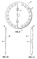
resilient member 80 is shown.Resilient member 80 comprises a centrally located flarededge 82 and pointedtip 84 at each end. End region 86 adjacent to tip 84 is not bent and is in the same plane as most ofresilient member 80. At least one tapered side 88 leading topointed tip 84 facilitates entry ofresilient member 80 into the interior of the drum when the drum supporting hub (not shown) is twisted into one end a drum (not shown). If only one tapered side is utilized at each end of a resilient member, the tapered side should face the end of the drum into which the hub is inserted. The expression "tapered side" as employed herein is intended to indicate an edge leading to a pointed tip, the edge being inclined relative to the longitudinal centerline of a long thin substantially flat electrically conductive resilient member. - In FIG. 11, another embodiment of a long thin substantially flat electrically conductive
resilient member 90 is shown with flarededges 92 and a plurality ofpointed tips 94. Although only two pointedtips 94 at each end ofresilient member 90 are shown, three or more tips may be utilized if desired. - FIG. 12 illustrates another
drum supporting hub 100 of this invention.Hub 100 comprises a disk shapedmember 102 bearing arc shapedalignment ridges 104 and acircular ridge 106 which supports a pair of long thin substantially flat electrically conductiveresilient members 108 arranged perpendicular to another pair of long thin substantially flat electricallyresilient members 112.Resilient members straddle hole 110 which is provided for an axle shaft (not shown) to increase the surface area available for frictional engagement and electrical contact betweenresilient members hub 20 and drum (not shown) around the axle shaft. The space between each resilient member of a pair should be slightly less than the diameter of the axle shaft to ensure positive electrical contact with the axle shaft. - Although, the hubs illustrated in the drawings may be identical at each end of the drum, the drum supporting hubs need not be identical.
Claims (10)
- A hub (20, 50, 70, 100) adapted to support a drum (34), said hub including a disk shaped member (21, 102) having a circular periphery (24), drum alignment_means (30, 72, 104), a hole (26, 110) extending axially through the centre of said disk shaped member, and at least one long thin electrically conductive resilient member (10, 56, 76, 80, 90, 108, 112) secured to said disk shaped member, said resilient member having a section (16) adjacent said hole for electrical contact with an axle shaft (40, 54) and an end region (18, 88) terminating into at least one pointed tip (12, 84, 94) arranged adjacent said circular periphery (24) of said disk shaped member (21, 102) and extending beyond said drum alignment means (30, 72, 104), for positive engagement into the interior surface of said cylindrical drum (34) upon insertion of said hub into said drum to prevent slippage therebetween,
wherein
said long thin electrically conductive resilient member (10, 56, 76, 80, 90, 108, 112) has a central section (16) adjacent said hole and opposite first and second end regions (18, 88), each of which terminate into at least one pointed tip (12, 84, 94), and said resilient member between said first and second end regions (18, 88) forming a major plane substantially parallel and spaced to the axis of said disk shaped member, said first and second end regions (18, 88) being bent in opposite directions from each other or being in said major plane, with said pointed tips (12, 84, 94) of said first and second end regions (18, 88) extending beyond said drum alignment means (30, 72, 104) at locations not diametrically opposing each other with respect to the axis of said disk shaped member (21, 102) before inserting said resilient member into said drum. - A hub according to claim 1, wherein said central section (16) is arranged to interfere with the installation of said axle shaft (10) to be bowed in frictional contact with said axle (40) inserted through said hole.
- A hub according to claim 1 or 2, wherein at least an edge (14, 82, 92) of said resilient member (10, 56, 76, 80, 90,108, 112) facing said disk shaped member (21, 102) is flared in a direction away from said axis of said disk to initially contact an end of an axle (40) as it is inserted through said hole (26, 110) andlor wherein the edge of said resilient member facing away from said disk shaped member is flared in a direction away from said axis of said disk.
- A hub according to any one of claims 1 to 3, wherein each of said ends of said resilient member (90) terminates into a plurality of pointed tips (94).
- A hub according to any one of claim 1 to 4, wherein a first pair of said electrically conductive resilient members (10, 56, 80, 90, 108) are mounted parallel to each other on said disk shaped member (21) on opposite sides of said hole (26) with flared edges (14, 82, 92) facing away from said axis and, optionally, wherein a second pair of said flat electrically conductive resilient members (112) are mounted parallel to each other on said disk shaped member on opposite sides of said hole and perpendicular to said first pair of said electrically conductive resilient members (108).
- A hub according to any one of claims 1 to 5, wherein said disk shaped member comprises an annular outer member (52) having a centrally located hole (62) into which a bearing member (54) has been mounted, said flat electrically conductive resilient member (56) being carried by said bearing member.
- An electrostatographic imaging member assembly comprising a hollow cylindrical electrically conductive substrate (36) having an interior surface and a coated outer surface (38) and a drum supporting hub of any one of claims 1 to 6, mounted on at least one end of said conductive substrate, and having the pointed tips (12) of said at least one resilient member embedded into said interior surface of said substrate.
- An electrostatographic imaging process comprising rotating said electrostatographic imaging member assembly of claim 7 in a direction generally opposite the direction in which each of said ends of said resilient member (10, 56, 76, 108, 112) are bent, forming an electrostatic latent image on said coated outer surface and developing said electrostatic latent image with a toner to form a toner image corresponding to said electrostatic latent image.
- A process for fabricating an electrostatographic imaging member assembly comprising providing a hollow cylindrically shaped electrostatographic imaging member having an interior surface, a coated outer surface and two ends, providing a drum supporting hub (20, 50, 70, 100) of any one of claims 1 to 6, and inserting said hub with a twisting motion into one of said ends of said hollow cylindrically shaped electrostatographic imaging member to bend said electrically conductive resilient member (10, 56, 76, 80, 90, 108, 112) whereby said pointed tip (12, 84, 94) at each end of said resilient member engages said interior surface to retain said hub in an end of said hollow cylindrically shaped electrostatographic imaging member.
- A process according to claim 9, including engaging a flared edge (14, 82, 92) of said central section (16) with an axle inserted through said hole (26, 110) whereby said flared edge is urged away form the axis of said disk.
Applications Claiming Priority (2)
| Application Number | Priority Date | Filing Date | Title |
|---|---|---|---|
| US08/177,033 US5357321A (en) | 1994-01-04 | 1994-01-04 | Drum supporting hub and drum assembly |
| US177033 | 1994-01-04 |
Publications (3)
| Publication Number | Publication Date |
|---|---|
| EP0661603A2 EP0661603A2 (en) | 1995-07-05 |
| EP0661603A3 EP0661603A3 (en) | 1996-01-10 |
| EP0661603B1 true EP0661603B1 (en) | 2001-09-26 |
Family
ID=22646914
Family Applications (1)
| Application Number | Title | Priority Date | Filing Date |
|---|---|---|---|
| EP95300004A Expired - Lifetime EP0661603B1 (en) | 1994-01-04 | 1995-01-03 | Drum supporting hub and drum assembly |
Country Status (5)
| Country | Link |
|---|---|
| US (1) | US5357321A (en) |
| EP (1) | EP0661603B1 (en) |
| JP (1) | JPH07219390A (en) |
| CA (1) | CA2139459C (en) |
| DE (1) | DE69522839T2 (en) |
Families Citing this family (19)
| Publication number | Priority date | Publication date | Assignee | Title |
|---|---|---|---|---|
| US5581325A (en) * | 1993-10-01 | 1996-12-03 | Canon Kabushiki Kaisha | Process cartridge having an electroconductive grounding member and an image forming apparatus using such a process cartridge |
| US5630196A (en) * | 1994-12-19 | 1997-05-13 | Xerox Corporation | Recyclable photoreceptor end flange |
| US5613931A (en) * | 1994-12-19 | 1997-03-25 | Xerox Corporation | Segmented end bell |
| US5599265A (en) * | 1994-12-19 | 1997-02-04 | Xerox Corporation | Barbed ring flange assembly |
| US5634175A (en) * | 1995-03-28 | 1997-05-27 | Steven Bruce Michlin | Electrical contact device for developer roller of toner cartridge |
| US5655182A (en) * | 1995-06-07 | 1997-08-05 | Xerox Corporation | Method and apparatus for reusing a photoreceptor and gear assembly |
| US5579093A (en) * | 1995-06-07 | 1996-11-26 | Xerox Corporation | Resiliently biased end caps for photoconductive drums |
| JP3323696B2 (en) * | 1995-06-13 | 2002-09-09 | キヤノン株式会社 | Ground member, electrophotographic photosensitive drum, process cartridge, and electrophotographic image forming apparatus |
| US5752136A (en) * | 1995-09-29 | 1998-05-12 | Xerox Corporation | Imaging member end flange and end flange assembly |
| US5802443A (en) * | 1996-02-08 | 1998-09-01 | Fuji Xerox Co., Ltd. | Reinforced thin cylindrical structure, image fixing device using this cylindrical structure, and method for manufacturing reinforced thin cylindrical structure |
| US5749028A (en) * | 1996-06-26 | 1998-05-05 | Xerox Corporation | Multi-size photoreceptor flange bearing |
| US5815773A (en) * | 1997-06-27 | 1998-09-29 | Xerox Corporation | Composite photoreceptor flange |
| US6157038A (en) * | 1998-12-11 | 2000-12-05 | Xerox Corporation | Mounting electrostatographic end flange |
| US6104896A (en) * | 1999-07-16 | 2000-08-15 | Xerox Corporation | Apparatus and method for forming an interference fit |
| US6490426B1 (en) | 2000-11-03 | 2002-12-03 | Xerox Corporation | Modular imaging member flange assembly |
| US7155143B2 (en) * | 2004-11-10 | 2006-12-26 | Xerox Corporation | Silencer for an imaging device photoreceptor |
| US7346292B2 (en) * | 2005-07-28 | 2008-03-18 | Static Control Components, Inc. | Systems and methods for remanufacturing imaging components |
| KR100850716B1 (en) | 2006-12-01 | 2008-08-06 | 삼성전자주식회사 | Image Former and Manufacturing Method Thereof |
| JP5092856B2 (en) * | 2008-04-09 | 2012-12-05 | ブラザー工業株式会社 | Electrophotographic photoreceptor |
Family Cites Families (21)
| Publication number | Priority date | Publication date | Assignee | Title |
|---|---|---|---|---|
| US3536397A (en) * | 1967-10-13 | 1970-10-27 | Xerox Corp | Xerographic apparatus |
| US4040157A (en) * | 1976-01-08 | 1977-08-09 | Xerox Corporation | Drum support apparatus |
| US4105345A (en) * | 1976-02-27 | 1978-08-08 | Xerox Corporation | Expandable photoreceptor endbells |
| DE2615617A1 (en) * | 1976-04-09 | 1977-10-20 | Agfa Gevaert Ag | ELECTROSTATIC COPY DEVICE |
| JPS6015942B2 (en) * | 1976-09-24 | 1985-04-23 | オリンパス光学工業株式会社 | How to attach and detach the photosensitive drum of an electrophotographic device |
| US4120576A (en) * | 1977-04-04 | 1978-10-17 | Xerox Corporation | Drum support apparatus |
| DE2717055A1 (en) * | 1977-04-18 | 1978-10-19 | Siemens Ag | DEVICE FOR STORING A DRUM USED AS AN INTERMEDIATE CARRIER IN AN ELECTROSTATIC PRINCIPLE PRINTER OR COPY DEVICE |
| US4161357A (en) * | 1977-09-02 | 1979-07-17 | Xerox Corporation | Photoreceptor heating apparatus |
| US4326793A (en) * | 1980-03-24 | 1982-04-27 | Burroughs Corporation | Full cantilever structural support apparatus for rotatable electrophotographic drum |
| JPS57141676A (en) * | 1981-02-25 | 1982-09-02 | Canon Inc | Drum flange |
| JPS5813559U (en) * | 1981-07-17 | 1983-01-27 | 株式会社リコー | Mounting structure of cylindrical photoreceptor |
| US4561763A (en) * | 1984-08-03 | 1985-12-31 | Xerox Corporation | Drum support apparatus |
| JPS6156379A (en) * | 1984-08-28 | 1986-03-22 | Fuji Xerox Co Ltd | Photosensitive drum of copying machine or the like |
| DE3631494A1 (en) * | 1985-09-17 | 1987-03-26 | Canon Kk | IMAGE CARRIER ELEMENT WITH RELATED DRIVE MECHANISM |
| GB2180796B (en) * | 1985-09-17 | 1990-05-09 | Canon Kk | Replaceable image bearing member for an image forming apparatus. |
| DE3703942A1 (en) * | 1987-02-09 | 1988-08-18 | Siemens Ag | GAME-FREE STORAGE DEVICE FOR PHOTO LADDER DRUMING IN PRINT OR COPY DEVICES |
| JPH089732Y2 (en) * | 1989-07-11 | 1996-03-21 | 三田工業株式会社 | Photoconductor drum |
| US4975743A (en) * | 1989-08-21 | 1990-12-04 | Surti Tyrone N | Process cartridge having removable drive means |
| US5151737A (en) * | 1990-06-04 | 1992-09-29 | Eastman Kodak Company | Photoconductive drum having expandable mount |
| US5210574A (en) * | 1991-03-08 | 1993-05-11 | Mita Industrial Co., Ltd. | Photosensitive drum body-mounting mechanism including a drive coupling member with a coupling protrusion adapted to bite into the inner surface of the mechanism's photosensitive drum |
| JP2758534B2 (en) * | 1992-07-13 | 1998-05-28 | 三田工業株式会社 | Image carrier support structure |
-
1994
- 1994-01-04 US US08/177,033 patent/US5357321A/en not_active Expired - Lifetime
-
1995
- 1995-01-03 DE DE69522839T patent/DE69522839T2/en not_active Expired - Fee Related
- 1995-01-03 EP EP95300004A patent/EP0661603B1/en not_active Expired - Lifetime
- 1995-01-03 CA CA002139459A patent/CA2139459C/en not_active Expired - Fee Related
- 1995-01-04 JP JP7000048A patent/JPH07219390A/en active Pending
Also Published As
| Publication number | Publication date |
|---|---|
| CA2139459A1 (en) | 1995-07-05 |
| US5357321A (en) | 1994-10-18 |
| DE69522839D1 (en) | 2001-10-31 |
| CA2139459C (en) | 2000-02-15 |
| JPH07219390A (en) | 1995-08-18 |
| EP0661603A2 (en) | 1995-07-05 |
| DE69522839T2 (en) | 2002-03-28 |
| EP0661603A3 (en) | 1996-01-10 |
Similar Documents
| Publication | Publication Date | Title |
|---|---|---|
| CA2139459C (en) | Drum supporting hub and drum assembly | |
| US6490426B1 (en) | Modular imaging member flange assembly | |
| US5630196A (en) | Recyclable photoreceptor end flange | |
| EP1460482B1 (en) | Drum unit and earth plate used in the drum unit | |
| EP1685448B1 (en) | Photosensitive drum assembly and image forming apparatus | |
| US5599265A (en) | Barbed ring flange assembly | |
| US6336012B1 (en) | Developing device, process cartridge and electric energy supply part to developing roller | |
| US5752136A (en) | Imaging member end flange and end flange assembly | |
| JPH1130931A (en) | End flange of photoreceptor | |
| US6104896A (en) | Apparatus and method for forming an interference fit | |
| US5576803A (en) | Electrostatographic imaging drum end cap and drum assembly | |
| US6771915B2 (en) | Coupling arrangement including optical photoconductive drum and grounding plate | |
| EP0747776A2 (en) | End caps for cylindrical drums | |
| US8254801B2 (en) | Grounding assembly for a drum in an image forming apparatus | |
| JP3368703B2 (en) | Photoreceptor drum fixing structure | |
| EP0510659B1 (en) | Image forming apparatus | |
| JP4008898B2 (en) | Drum flange | |
| US5613931A (en) | Segmented end bell | |
| JP3502534B2 (en) | Manufacturing method of magnet roll | |
| JPH05297782A (en) | Photosensitive drum device | |
| JP2687051B2 (en) | Rotating drum mounting mechanism in image generator | |
| JPH04323671A (en) | Image forming device | |
| JPH059735Y2 (en) | ||
| JPH02254484A (en) | Flange for mounting electrophotographic sensitive body | |
| JP2005189689A (en) | Photoreceptor drum |
Legal Events
| Date | Code | Title | Description |
|---|---|---|---|
| PUAI | Public reference made under article 153(3) epc to a published international application that has entered the european phase |
Free format text: ORIGINAL CODE: 0009012 |
|
| AK | Designated contracting states |
Kind code of ref document: A2 Designated state(s): DE FR GB |
|
| PUAL | Search report despatched |
Free format text: ORIGINAL CODE: 0009013 |
|
| AK | Designated contracting states |
Kind code of ref document: A3 Designated state(s): DE FR GB |
|
| 17P | Request for examination filed |
Effective date: 19960710 |
|
| 17Q | First examination report despatched |
Effective date: 19980324 |
|
| GRAG | Despatch of communication of intention to grant |
Free format text: ORIGINAL CODE: EPIDOS AGRA |
|
| GRAG | Despatch of communication of intention to grant |
Free format text: ORIGINAL CODE: EPIDOS AGRA |
|
| GRAH | Despatch of communication of intention to grant a patent |
Free format text: ORIGINAL CODE: EPIDOS IGRA |
|
| GRAH | Despatch of communication of intention to grant a patent |
Free format text: ORIGINAL CODE: EPIDOS IGRA |
|
| GRAA | (expected) grant |
Free format text: ORIGINAL CODE: 0009210 |
|
| AK | Designated contracting states |
Kind code of ref document: B1 Designated state(s): DE FR GB |
|
| REF | Corresponds to: |
Ref document number: 69522839 Country of ref document: DE Date of ref document: 20011031 |
|
| REG | Reference to a national code |
Ref country code: GB Ref legal event code: IF02 |
|
| ET | Fr: translation filed | ||
| PLBE | No opposition filed within time limit |
Free format text: ORIGINAL CODE: 0009261 |
|
| STAA | Information on the status of an ep patent application or granted ep patent |
Free format text: STATUS: NO OPPOSITION FILED WITHIN TIME LIMIT |
|
| 26N | No opposition filed | ||
| PGFP | Annual fee paid to national office [announced via postgrant information from national office to epo] |
Ref country code: GB Payment date: 20021231 Year of fee payment: 9 |
|
| PGFP | Annual fee paid to national office [announced via postgrant information from national office to epo] |
Ref country code: FR Payment date: 20030110 Year of fee payment: 9 |
|
| PGFP | Annual fee paid to national office [announced via postgrant information from national office to epo] |
Ref country code: DE Payment date: 20030116 Year of fee payment: 9 |
|
| PG25 | Lapsed in a contracting state [announced via postgrant information from national office to epo] |
Ref country code: GB Free format text: LAPSE BECAUSE OF NON-PAYMENT OF DUE FEES Effective date: 20040103 |
|
| PG25 | Lapsed in a contracting state [announced via postgrant information from national office to epo] |
Ref country code: DE Free format text: LAPSE BECAUSE OF NON-PAYMENT OF DUE FEES Effective date: 20040803 |
|
| GBPC | Gb: european patent ceased through non-payment of renewal fee |
Effective date: 20040103 |
|
| PG25 | Lapsed in a contracting state [announced via postgrant information from national office to epo] |
Ref country code: FR Free format text: LAPSE BECAUSE OF NON-PAYMENT OF DUE FEES Effective date: 20040930 |
|
| REG | Reference to a national code |
Ref country code: FR Ref legal event code: ST |