EP0661493B1 - Gas charging equipment - Google Patents
Gas charging equipment Download PDFInfo
- Publication number
- EP0661493B1 EP0661493B1 EP94309885A EP94309885A EP0661493B1 EP 0661493 B1 EP0661493 B1 EP 0661493B1 EP 94309885 A EP94309885 A EP 94309885A EP 94309885 A EP94309885 A EP 94309885A EP 0661493 B1 EP0661493 B1 EP 0661493B1
- Authority
- EP
- European Patent Office
- Prior art keywords
- gas
- turntable
- distributor
- charging
- container
- Prior art date
- Legal status (The legal status is an assumption and is not a legal conclusion. Google has not performed a legal analysis and makes no representation as to the accuracy of the status listed.)
- Expired - Lifetime
Links
Images
Classifications
-
- F—MECHANICAL ENGINEERING; LIGHTING; HEATING; WEAPONS; BLASTING
- F17—STORING OR DISTRIBUTING GASES OR LIQUIDS
- F17C—VESSELS FOR CONTAINING OR STORING COMPRESSED, LIQUEFIED OR SOLIDIFIED GASES; FIXED-CAPACITY GAS-HOLDERS; FILLING VESSELS WITH, OR DISCHARGING FROM VESSELS, COMPRESSED, LIQUEFIED, OR SOLIDIFIED GASES
- F17C5/00—Methods or apparatus for filling containers with liquefied, solidified, or compressed gases under pressures
- F17C5/002—Automated filling apparatus
- F17C5/005—Automated filling apparatus for gas bottles, such as on a continuous belt or on a merry-go-round
-
- F—MECHANICAL ENGINEERING; LIGHTING; HEATING; WEAPONS; BLASTING
- F17—STORING OR DISTRIBUTING GASES OR LIQUIDS
- F17C—VESSELS FOR CONTAINING OR STORING COMPRESSED, LIQUEFIED OR SOLIDIFIED GASES; FIXED-CAPACITY GAS-HOLDERS; FILLING VESSELS WITH, OR DISCHARGING FROM VESSELS, COMPRESSED, LIQUEFIED, OR SOLIDIFIED GASES
- F17C13/00—Details of vessels or of the filling or discharging of vessels
- F17C13/02—Special adaptations of indicating, measuring, or monitoring equipment
- F17C13/023—Special adaptations of indicating, measuring, or monitoring equipment having the mass as the parameter
-
- F—MECHANICAL ENGINEERING; LIGHTING; HEATING; WEAPONS; BLASTING
- F17—STORING OR DISTRIBUTING GASES OR LIQUIDS
- F17C—VESSELS FOR CONTAINING OR STORING COMPRESSED, LIQUEFIED OR SOLIDIFIED GASES; FIXED-CAPACITY GAS-HOLDERS; FILLING VESSELS WITH, OR DISCHARGING FROM VESSELS, COMPRESSED, LIQUEFIED, OR SOLIDIFIED GASES
- F17C2205/00—Vessel construction, in particular mounting arrangements, attachments or identifications means
- F17C2205/03—Fluid connections, filters, valves, closure means or other attachments
- F17C2205/0302—Fittings, valves, filters, or components in connection with the gas storage device
- F17C2205/0323—Valves
- F17C2205/0326—Valves electrically actuated
-
- F—MECHANICAL ENGINEERING; LIGHTING; HEATING; WEAPONS; BLASTING
- F17—STORING OR DISTRIBUTING GASES OR LIQUIDS
- F17C—VESSELS FOR CONTAINING OR STORING COMPRESSED, LIQUEFIED OR SOLIDIFIED GASES; FIXED-CAPACITY GAS-HOLDERS; FILLING VESSELS WITH, OR DISCHARGING FROM VESSELS, COMPRESSED, LIQUEFIED, OR SOLIDIFIED GASES
- F17C2221/00—Handled fluid, in particular type of fluid
- F17C2221/03—Mixtures
- F17C2221/032—Hydrocarbons
- F17C2221/035—Propane butane, e.g. LPG, GPL
-
- F—MECHANICAL ENGINEERING; LIGHTING; HEATING; WEAPONS; BLASTING
- F17—STORING OR DISTRIBUTING GASES OR LIQUIDS
- F17C—VESSELS FOR CONTAINING OR STORING COMPRESSED, LIQUEFIED OR SOLIDIFIED GASES; FIXED-CAPACITY GAS-HOLDERS; FILLING VESSELS WITH, OR DISCHARGING FROM VESSELS, COMPRESSED, LIQUEFIED, OR SOLIDIFIED GASES
- F17C2223/00—Handled fluid before transfer, i.e. state of fluid when stored in the vessel or before transfer from the vessel
- F17C2223/01—Handled fluid before transfer, i.e. state of fluid when stored in the vessel or before transfer from the vessel characterised by the phase
- F17C2223/0146—Two-phase
- F17C2223/0153—Liquefied gas, e.g. LPG, GPL
-
- F—MECHANICAL ENGINEERING; LIGHTING; HEATING; WEAPONS; BLASTING
- F17—STORING OR DISTRIBUTING GASES OR LIQUIDS
- F17C—VESSELS FOR CONTAINING OR STORING COMPRESSED, LIQUEFIED OR SOLIDIFIED GASES; FIXED-CAPACITY GAS-HOLDERS; FILLING VESSELS WITH, OR DISCHARGING FROM VESSELS, COMPRESSED, LIQUEFIED, OR SOLIDIFIED GASES
- F17C2223/00—Handled fluid before transfer, i.e. state of fluid when stored in the vessel or before transfer from the vessel
- F17C2223/03—Handled fluid before transfer, i.e. state of fluid when stored in the vessel or before transfer from the vessel characterised by the pressure level
- F17C2223/033—Small pressure, e.g. for liquefied gas
-
- F—MECHANICAL ENGINEERING; LIGHTING; HEATING; WEAPONS; BLASTING
- F17—STORING OR DISTRIBUTING GASES OR LIQUIDS
- F17C—VESSELS FOR CONTAINING OR STORING COMPRESSED, LIQUEFIED OR SOLIDIFIED GASES; FIXED-CAPACITY GAS-HOLDERS; FILLING VESSELS WITH, OR DISCHARGING FROM VESSELS, COMPRESSED, LIQUEFIED, OR SOLIDIFIED GASES
- F17C2250/00—Accessories; Control means; Indicating, measuring or monitoring of parameters
- F17C2250/03—Control means
- F17C2250/032—Control means using computers
-
- F—MECHANICAL ENGINEERING; LIGHTING; HEATING; WEAPONS; BLASTING
- F17—STORING OR DISTRIBUTING GASES OR LIQUIDS
- F17C—VESSELS FOR CONTAINING OR STORING COMPRESSED, LIQUEFIED OR SOLIDIFIED GASES; FIXED-CAPACITY GAS-HOLDERS; FILLING VESSELS WITH, OR DISCHARGING FROM VESSELS, COMPRESSED, LIQUEFIED, OR SOLIDIFIED GASES
- F17C2250/00—Accessories; Control means; Indicating, measuring or monitoring of parameters
- F17C2250/04—Indicating or measuring of parameters as input values
- F17C2250/0404—Parameters indicated or measured
- F17C2250/0421—Mass or weight of the content of the vessel
-
- F—MECHANICAL ENGINEERING; LIGHTING; HEATING; WEAPONS; BLASTING
- F17—STORING OR DISTRIBUTING GASES OR LIQUIDS
- F17C—VESSELS FOR CONTAINING OR STORING COMPRESSED, LIQUEFIED OR SOLIDIFIED GASES; FIXED-CAPACITY GAS-HOLDERS; FILLING VESSELS WITH, OR DISCHARGING FROM VESSELS, COMPRESSED, LIQUEFIED, OR SOLIDIFIED GASES
- F17C2250/00—Accessories; Control means; Indicating, measuring or monitoring of parameters
- F17C2250/04—Indicating or measuring of parameters as input values
- F17C2250/0404—Parameters indicated or measured
- F17C2250/0426—Volume
-
- F—MECHANICAL ENGINEERING; LIGHTING; HEATING; WEAPONS; BLASTING
- F17—STORING OR DISTRIBUTING GASES OR LIQUIDS
- F17C—VESSELS FOR CONTAINING OR STORING COMPRESSED, LIQUEFIED OR SOLIDIFIED GASES; FIXED-CAPACITY GAS-HOLDERS; FILLING VESSELS WITH, OR DISCHARGING FROM VESSELS, COMPRESSED, LIQUEFIED, OR SOLIDIFIED GASES
- F17C2250/00—Accessories; Control means; Indicating, measuring or monitoring of parameters
- F17C2250/04—Indicating or measuring of parameters as input values
- F17C2250/0404—Parameters indicated or measured
- F17C2250/0443—Flow or movement of content
-
- F—MECHANICAL ENGINEERING; LIGHTING; HEATING; WEAPONS; BLASTING
- F17—STORING OR DISTRIBUTING GASES OR LIQUIDS
- F17C—VESSELS FOR CONTAINING OR STORING COMPRESSED, LIQUEFIED OR SOLIDIFIED GASES; FIXED-CAPACITY GAS-HOLDERS; FILLING VESSELS WITH, OR DISCHARGING FROM VESSELS, COMPRESSED, LIQUEFIED, OR SOLIDIFIED GASES
- F17C2250/00—Accessories; Control means; Indicating, measuring or monitoring of parameters
- F17C2250/06—Controlling or regulating of parameters as output values
- F17C2250/0605—Parameters
- F17C2250/0636—Flow or movement of content
-
- F—MECHANICAL ENGINEERING; LIGHTING; HEATING; WEAPONS; BLASTING
- F17—STORING OR DISTRIBUTING GASES OR LIQUIDS
- F17C—VESSELS FOR CONTAINING OR STORING COMPRESSED, LIQUEFIED OR SOLIDIFIED GASES; FIXED-CAPACITY GAS-HOLDERS; FILLING VESSELS WITH, OR DISCHARGING FROM VESSELS, COMPRESSED, LIQUEFIED, OR SOLIDIFIED GASES
- F17C2260/00—Purposes of gas storage and gas handling
- F17C2260/04—Reducing risks and environmental impact
- F17C2260/042—Reducing risk of explosion
-
- F—MECHANICAL ENGINEERING; LIGHTING; HEATING; WEAPONS; BLASTING
- F17—STORING OR DISTRIBUTING GASES OR LIQUIDS
- F17C—VESSELS FOR CONTAINING OR STORING COMPRESSED, LIQUEFIED OR SOLIDIFIED GASES; FIXED-CAPACITY GAS-HOLDERS; FILLING VESSELS WITH, OR DISCHARGING FROM VESSELS, COMPRESSED, LIQUEFIED, OR SOLIDIFIED GASES
- F17C2270/00—Applications
- F17C2270/05—Applications for industrial use
- F17C2270/059—Mass bottling, e.g. merry belts
Definitions
- the present invention relates to a fluid charging equipment for charging LP gas or the like and more particularly to an improvement of equipment for charging a predetermined amount of fluid, eg LP gas, automatically into each of gas containers conveyed onto a turntable.
- a predetermined amount of fluid eg LP gas
- it may be liquid which is charged into LP gas cylinders or containers, but they are still referred to as gas cylinders because any such liquid is unstable at ambient temperatures and the liquid flashes to gas when the container is opened to dispense the gas.
- the applicant in the present case has previously proposed an automatic LP gas charging equipment (Japanese Utility Model Laid Open No 62-34296) wherein each container is put on an electrobalance disposed on a carrying-in line to a turntable and is weighed, then the amount of gas to be charged into the container is calculated on the basis of the measured value and such amount of gas is charged into the container through a gas distributor and a gas charging valve while the container is moved by the turntable, further, there are used the gas distributor, an air distributor, solenoid valves, controllers and an optical fiber rotary joint.
- the solenoid valves and the controllers are arranged fixedly under the turntable, so at the time of installing the equipment in a gas charging factory, much time and labor are required for the mounting and wiring of the solenoid valves and controllers.
- the working efficiency is low but also inconvenience is encountered in maintenance and inspection.
- the gas charging valve is inferior in the instantaneousness of its closing motion and for this reason it has heretofore been impossible to obtain a high gas charging volume accuracy.
- the present invention has been accomplished in view of such circumstances and it is the object of the invention at least in its preferred form to provide a gas charging equipment capable of being installed in a factory at an improved working efficiency, permitting easy maintenance and inspection and attaining improvement in both gas charging volume accuracy and gas charging accuracy.
- JP-A-03033598 and JP-A-59093598 there is disclosed a charging equipment for charging fluid into containers comprising a turntable having a plurality of peripherally arranged locations each for receiving a container to be charged with said fluid as the turntable rotates, and the turntable also carries a corresponding plurality of fluid supply lines and a central distributor by which said fluid from a common source.
- There are also individual programmable control means on the turntable for said supply fluid which are connected for controlling the supply of said fluid to the individual containers, to fill same to the required degree based upon the supply of weight data of each container to the control means, when the container is placed upon a said location.
- a charging equipment for charging fluid into containers comprising a turntable having a plurality of peripherally arranged portions each for receiving a container to be charged with said fluid as the turntable rotates, wherein said turntable also carries a corresponding plurality of fluid supply lines and a central distributor by which said supply lines are supplied with said fluid from a common source, individual programmable control means on the turntable for said supply lines and connected to a central processing unit (CPU) for controlling the supply of said fluid to the individual container, to fill same to the required degree, based upon the supply of weight data to the control means and relating to the container when it is placed upon a said portion in the turntable for filling, characterised in that said CPU is connected to said control means by an optical connection.
- CPU central processing unit
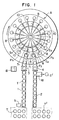
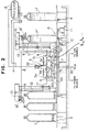
- Fig. 1 is a schematic plan view of an LP gas charging equipment according to an embodiment of the present invention and Fig. 2 is a developed sectional side view thereof.
- the reference mark A denotes a turntable
- the numeral 1 denotes a carrying-in or feed line
- numeral 2 denotes a carrying-out or discharge line
- numerals 3 and 4 each denote an electrobalance
- numeral 5 denotes a gas distributor
- 6 denotes an air distributor
- 7 denotes an electric distributor
- T denotes a container not charged with gas yet
- T' denotes a container already charged with gas
- B denotes a control panel which has a central processing unit (CPU) and is connected to an input operating portion b, electrobalances 3, 4 and further to controllers 33 which will be described later.
- CPU central processing unit
- the turntable A is installed on a floor surface so as to be rotatable horizontally and it is rotated continuously at low speed by means of a drive unit 11.
- container rest or holder portions P 1 , P 2 ... P n On the turntable A are positioned and arranged container rest or holder portions P 1 , P 2 ... P n at equal intervals and on the same circumference, and near those container rest portions are erected support rods 12 which hold gas charging hoses 8, respectively.
- an air distributor 6 and an electric distributor 7 are disposed in a plural-stage fashion, and around those distributors are arranged solenoid valves 15 and controllers 33 and erected the same number of support rods 30, 30, ... as the number of the container rest portions P 1 , P 2... P n.
- a table 31 is mounted bridgewise over the support rods 30, 30,... and a gas distributor 5 is supported on the table 31 so as to be rotatable integrally with the turntable A.
- the controllers 33 are each provided with a central processing unit (CPU) and have address memories in corresponding relation to the container rest portions P 1 , P 2 , ... P n .
- CPU central processing unit
- the gas distributor 5 has a unitary body structure and LP gas is fed thereto from a tank 13 and from above the turntable A through a high-pressure swivel 32. To the peripheral surface of the gas distributor 5 are manifoldly connected the same number of gas distributing pipes S 1 , S 2 ... S n as the number of the container rest portions P 1 , P 2 ... P n .
- the gas distributing pipes S 1 , S 2 , ... S n are simultaneously supplied with gas and are laid along the support rods 30, 30, ... and are connected to flowmeters 9 fixed to the support rods 30, 30
- the distal ends of the gas distributing pipes are connected respectively through connectors 17 to the corresponding gas charging hoses 8 held by the support rods 12.
- the gas distributor 5 can be supported by utilizing the space formed above the air distributor 6 but also the manifoldly branched gas distributing pipes S 1 , S 2 , ... S n can be laid in an orderly way along the support rods 30, 30, ....
- the pipes on the turntable A which are apt to be complicated can be arranged neatly, whereby the piping and checking works can be done easily.
- each gas charging hose 8 is provided with a gas charger 8' for mounting and removal with respect to an upper-end opening of a container T.
- the gas charger 8' is provided with a gas charging valve 10 adapted to be opened and closed by air from the air distributor 6.
- the air distributor 6 is constituted by an air rotary joint which comprises an inner fixed body and an outer rotatable body, and air hoses h 1 , h 2 , ... h n for the distribution of air are arranged along the said rotatable body.
- the air hoses h 1 , h 2 ... h n are connected to the corresponding gas charging valves 10 through the solenoid valves 15 arranged on the turntable A. Upon turning ON of a solenoid valve 15, the corresponding gas charging valve 10 is opened, while upon turning OFF of the valve 15, the valve 10 is closed.
- the electric distributor 7 is a hollow, electric rotary joint. Wires branched on the outer periphery of the distributor 7 are connected to the controllers 33, and the solenoid valves 15 are connected to and controlled by the controllers 33.
- the solenoid valves 15, ... may be arranged individually in a dispersed form, or may be concentrated on one place.
- the flowmeters 9 which are turbo-flowmeters, measure the flow rate of gas by counting the number of pulses which are formed upon flowing of gas through each flowmeter. They are connected to the controllers 33 so that the pulse signals obtained are transmitted to the controllers.
- the pulse signal obtained in each flowmeter 9 is transmitted to the corresponding controller 33, in which the number of pulses is counted.
- a signal for actuating the associated solenoid valve 15 is provided from the controller 33 to close the associated gas charging valve 10 and at this time the relevant container will be correctly filled.
- the control panel B is provided with a central processing unit (CPU) and is connected to electrobalances 3, 4 and also to an input operating portion.
- CPU central processing unit
- the amount of gas to be charged is calculated on the basis of data such as measured data provided from those components, then the thus- calculated gas charging volume is transmitted to the controller 33 concerned, and when the container T concerned is put on any one of the container rest portions P 1 , P 2 ... P n , such gas charging volume is stored in the address memory corresponding to the container rest portion with the container T put thereon.
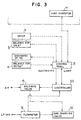
- each controller 33 and the control panel B is performed by optical communication through an optical fiber rotary joint 34.
- optical fiber rotary joint 34 is disposed on the air distributor 6, more specifically on the axis of the air distributor 6 and electric distributor 7, and optical fiber 35 is extended through central cavities of both distributors 6 and 7.
- the control panel B is connected to a host computer H (Fig. 3) disposed within an office or a control center, and required data on the containers T such as customers' names and specified amounts of gas to be charged are inputted to and outputted from the host computer H.
- a host computer H Fig. 3
- the numeral 18 denotes a discharge line for the discharge of defective containers.
- the charger 8' to each container T Every time the operator sets the charger 8' to each container T, the predetermined amount of gas is charged into the container in accordance with ON-OFF operating of the associated solenoid valve 15 which is controlled by the corresponding controller 33, and through the corresponding flowmeter 9, during movement of the container T which rotates together with the turntable A.
- Setting of the charger 8' to each container may be automatic.
- the gas charging volume data accumulated in the corresponding controller 33 are stored in the memory address corresponding to that container rest portion, so it is not always required to put containers in the regular order onto the container rest portions P 1 , P 2 , ... P n , but such regular order may be skipped, for example due to delay in the weighing or carrying-in operation. Thus, there is no fear of mistake caused by container positioning in the gas charging work.
- solenoid valves and controllers are arranged on the turntable, not only the installation work efficiency is improved but also maintenance and inspection are easy.
- the gas charging volume obtained by calculation in the control panel is stored in the address memory of each controller on the turntable and the gas charging valves are opened and closed through communication with the solenoid valves and flowmeters on the turntable, the response characteristic to a signal command is improved and there is attained instantaneousness of the gas charging valve closing motion, whereby the gas charging volume accuracy is improved.
Landscapes
- Engineering & Computer Science (AREA)
- Mechanical Engineering (AREA)
- General Engineering & Computer Science (AREA)
- Filling Or Discharging Of Gas Storage Vessels (AREA)
Description
Claims (12)
- A charging equipment for charging fluid into containers comprising a turntable (A) having a plurality of peripherally arranged portions (P1, P2, Pn) each for receiving a container (T) to be charged with said fluid as the turntable (A) rotates, wherein said turntable also carries a corresponding plurality of fluid supply lines (8, 21) and a central distributor (5) by which said supply lines are supplied with said fluid from a common source (13), individual programmable control means (15, 33) on the turntable for said supply lines and connected to a central processing unit (CPU) for controlling the supply of said fluid to the individual containers (T), to fill same to the required degree, based upon the supply of weight data to the control means and relating to the container when it is placed upon a said portion in the turntable for filling, characterised in that said CPU is connected to said control means (15, 33) by an optical connection.
- A charging equipment according to Claim 1, characterised by an electrobalance (3) supplying said weight data.
- A charging equipment according to Claim 2, characterised by a feed line (1) for feeding the containers (T) to be filled, one by one to the turntable (A) and said electrobalance (3) is connected in said feed line (1).
- A charging equipment according to Claim 2 or 3, characterised by a control panel (B) which includes said CPU.
- A charging equipment according to any preceding claim, characterised in that said control means (15, 33) each comprises a gas charging valve (10) and a flowmeter (17).
- A charging equipment according to Claim 5, characterised in that each gas charging valve (10) is under the control of a compressed air supply (6) in turn controlled by the control means (15, 33) and the flowmeter (17) is operated sufficiently to supply the required amount of gas based upon the weight data when the valve is open.
- A charging equipment according to any preceding claim characterised in that the turntable (A) carries centrally an air distributor (6) connected to air supply lines (h1, h2, hn) and an electric distributor (7) connected to the programmable control means (15, 33) to supply compressed air to the gas charging lines (8, 21) to control the flow of gas to the cylinders (T) and to provide electrical supplies to the control means (15, 33).
- A charging equipment according to claim 7, characterised by solenoid valves (15) in said air supply lines (h1, h2...hn).
- A charging equipment according to Claim 8 characterised in that an optical fibre rotary joint is disposed above the air distributor and electric distributor and there is optical communication, between the control means (15,33) and means supplying said weight data, by optical fibre means (35) passing through cavities in said distributors (6,7).
- A charging equipment according to any preceding claim characterised in that a fluid supply pipe is connected from above the turntable (A) to the gas distributor (5).
- A charging equipment according to any preceding claim, characterised in that the said fluid is LP gas.
- A gas charging equipment for LP gas, having an electrobalance disposed on a carrying-in line to a turntable to weigh containers and a control panel to which said electrobalance is connected and which has a central processing unit; gas charging valves which are opened while said containers are moved by said turntable to supply the gas to the containers from a gas distributor; and flowmeters for measuring the flow rate of gas at the time of gas charging, the amount of the gas to be charged into each said container being calculated by the central processing unit on the basis of the value measured by said electrobalance to control the gas charging operation, characterised in that:an air distributor and an electric distributor are disposed centrally on said turntable, solenoid valves and controllers are arranged around said distributors, a predetermined number of container rest portions are arranged at equal intervals on the outer peripheral portion of the turntable, and the gas distributor is disposed centrally above the turntable so as to rotate integrally with the turntable;a gas supply pipe is connected from above the turntable to the gas distributor, gas distributing pipes are connected manifoldly to the gas distributor, and flowmeters and gas charging valves are disposed in those gas charging hoses;air hoses are connected manifoldly to said air distributor and also connected to the gas charging valves through said solenoid valves to open and close the gas charging valves;said controllers are each provided with a central processing unit and have address memories corresponding to said container rest portions, and said solenoid valves and said flowmeters are connected to the controllers in corresponding relation to the addresses of said memories; andan optical fiber rotary joint is disposed above and on the axis of both said air distributor and electric distributor, and optical communication between said controllers and said control panel is performed by utilising central cavities of both said distributors.
Applications Claiming Priority (2)
| Application Number | Priority Date | Filing Date | Title |
|---|---|---|---|
| JP338178/93 | 1993-12-28 | ||
| JP5338178A JP2648563B2 (en) | 1993-12-28 | 1993-12-28 | Gas filling equipment |
Publications (2)
| Publication Number | Publication Date |
|---|---|
| EP0661493A1 EP0661493A1 (en) | 1995-07-05 |
| EP0661493B1 true EP0661493B1 (en) | 1998-08-05 |
Family
ID=18315660
Family Applications (1)
| Application Number | Title | Priority Date | Filing Date |
|---|---|---|---|
| EP94309885A Expired - Lifetime EP0661493B1 (en) | 1993-12-28 | 1994-12-22 | Gas charging equipment |
Country Status (5)
| Country | Link |
|---|---|
| EP (1) | EP0661493B1 (en) |
| JP (1) | JP2648563B2 (en) |
| KR (1) | KR950019358A (en) |
| DE (1) | DE69412226D1 (en) |
| TW (1) | TW262526B (en) |
Families Citing this family (7)
| Publication number | Priority date | Publication date | Assignee | Title |
|---|---|---|---|---|
| KR100637407B1 (en) * | 1998-01-30 | 2006-10-23 | 코산 크리스플랜트 에이/에스 | Devices for filling liquefied gas inside containers |
| FR2787551B1 (en) * | 1998-12-22 | 2001-07-20 | Elf Antargaz | DEVICE FOR MONITORING THE LEVEL OF LIQUID GAS IN A FILLED GAS BOTTLE IN A GAS BOTTLE FILLING SYSTEM |
| EP1987283B1 (en) * | 2006-02-10 | 2019-04-10 | Kosan Crisplant A/S | A filling system for filling substance into containers |
| RU2332612C1 (en) * | 2007-01-26 | 2008-08-27 | Закрытое акционерное общество "Заречье" | Unit to fill cylinders with liquefied gas |
| CN117249379B (en) * | 2023-10-31 | 2025-08-12 | 重庆同辉气体有限公司 | Gas filling system and method |
| CN117489967B (en) * | 2023-10-31 | 2024-05-17 | 英德市西洲气体有限公司 | Industrial gas filling system and filling process |
| US20250197109A1 (en) * | 2023-12-18 | 2025-06-19 | Michael Foley | User Propane Tank Moving Apparatus |
Family Cites Families (4)
| Publication number | Priority date | Publication date | Assignee | Title |
|---|---|---|---|---|
| JPS5993598A (en) * | 1982-11-20 | 1984-05-30 | Meiko Sangyo Kk | Lp gas charging device |
| JPS60125983A (en) * | 1984-01-24 | 1985-07-05 | Sony Corp | Tape cassette |
| JPH0633856B2 (en) * | 1989-06-27 | 1994-05-02 | 明光産業株式会社 | Automatic specific gravity correction method for LP gas filling device |
| FR2681934B1 (en) * | 1991-09-27 | 1993-12-31 | Automation Mecanique Provencale | METHOD AND INSTALLATION FOR FILLING LIQUID GAS BOTTLES AND FOR MONITORING SUCH BOTTLES AFTER FILLING. |
-
1993
- 1993-12-28 JP JP5338178A patent/JP2648563B2/en not_active Expired - Lifetime
-
1994
- 1994-11-25 TW TW083110962A patent/TW262526B/zh active
- 1994-12-22 DE DE69412226T patent/DE69412226D1/en not_active Expired - Lifetime
- 1994-12-22 EP EP94309885A patent/EP0661493B1/en not_active Expired - Lifetime
- 1994-12-27 KR KR1019940037424A patent/KR950019358A/en not_active Ceased
Also Published As
| Publication number | Publication date |
|---|---|
| DE69412226D1 (en) | 1998-09-10 |
| JPH07198096A (en) | 1995-08-01 |
| JP2648563B2 (en) | 1997-09-03 |
| TW262526B (en) | 1995-11-11 |
| KR950019358A (en) | 1995-07-22 |
| EP0661493A1 (en) | 1995-07-05 |
Similar Documents
| Publication | Publication Date | Title |
|---|---|---|
| KR100460596B1 (en) | Weight-based, multiple-filler filling machine | |
| RU2279378C2 (en) | Device for container filling with products, preferably with liquids | |
| WO1997034707A1 (en) | Paint system with color change canisters | |
| EP0661493A1 (en) | Gas charging equipment | |
| EP1363835B1 (en) | Container filling machine | |
| CN106017537A (en) | Metering unit | |
| CN112534174B (en) | Method and apparatus for helium gas storage and supply | |
| GB2288168A (en) | Master - slave filling valve system for bottling machine | |
| JPS6361560B2 (en) | ||
| AU629905B2 (en) | Method of and apparatus for weighing and taking out powdered dye | |
| KR102437265B1 (en) | Supply control system for iso tank | |
| GB2151362A (en) | A dispensing head | |
| JP2024531290A5 (en) | ||
| JPS5993689A (en) | Device for simultaneously filling fluidized medium into plurality of vessel | |
| KR100468517B1 (en) | Controlling Device of Central Supply of Medicinal Fluid for Semiconductor and LCD Exposure | |
| JPH064160Y2 (en) | LP gas filling device | |
| JPH0633856B2 (en) | Automatic specific gravity correction method for LP gas filling device | |
| JPH0796904A (en) | High-speed filling machine | |
| RU2718490C1 (en) | Drain device with possibility of car-by-car recording and pumping of oil products from railway tanks to storage reservoirs | |
| US9052129B2 (en) | Charging device for cooling system | |
| US20040084087A1 (en) | Apparatus and method for controlling and distributing gas flow | |
| JPS63298161A (en) | Distributor | |
| CN219995087U (en) | Centralized kerosene distribution system and transformer manufacturing plant | |
| CN204903988U (en) | Automatic fertile intelligent system of configuration liquid | |
| CN215326857U (en) | Liquid fertilizer filling system |
Legal Events
| Date | Code | Title | Description |
|---|---|---|---|
| PUAI | Public reference made under article 153(3) epc to a published international application that has entered the european phase |
Free format text: ORIGINAL CODE: 0009012 |
|
| AK | Designated contracting states |
Kind code of ref document: A1 Designated state(s): DE FR GB IT |
|
| 17P | Request for examination filed |
Effective date: 19951107 |
|
| 17Q | First examination report despatched |
Effective date: 19970514 |
|
| GRAG | Despatch of communication of intention to grant |
Free format text: ORIGINAL CODE: EPIDOS AGRA |
|
| GRAG | Despatch of communication of intention to grant |
Free format text: ORIGINAL CODE: EPIDOS AGRA |
|
| GRAH | Despatch of communication of intention to grant a patent |
Free format text: ORIGINAL CODE: EPIDOS IGRA |
|
| GRAH | Despatch of communication of intention to grant a patent |
Free format text: ORIGINAL CODE: EPIDOS IGRA |
|
| GRAH | Despatch of communication of intention to grant a patent |
Free format text: ORIGINAL CODE: EPIDOS IGRA |
|
| GRAA | (expected) grant |
Free format text: ORIGINAL CODE: 0009210 |
|
| AK | Designated contracting states |
Kind code of ref document: B1 Designated state(s): DE FR GB IT |
|
| PG25 | Lapsed in a contracting state [announced via postgrant information from national office to epo] |
Ref country code: IT Free format text: LAPSE BECAUSE OF FAILURE TO SUBMIT A TRANSLATION OF THE DESCRIPTION OR TO PAY THE FEE WITHIN THE PRESCRIBED TIME-LIMIT;WARNING: LAPSES OF ITALIAN PATENTS WITH EFFECTIVE DATE BEFORE 2007 MAY HAVE OCCURRED AT ANY TIME BEFORE 2007. THE CORRECT EFFECTIVE DATE MAY BE DIFFERENT FROM THE ONE RECORDED. Effective date: 19980805 |
|
| REF | Corresponds to: |
Ref document number: 69412226 Country of ref document: DE Date of ref document: 19980910 |
|
| ET | Fr: translation filed | ||
| PG25 | Lapsed in a contracting state [announced via postgrant information from national office to epo] |
Ref country code: DE Free format text: LAPSE BECAUSE OF FAILURE TO SUBMIT A TRANSLATION OF THE DESCRIPTION OR TO PAY THE FEE WITHIN THE PRESCRIBED TIME-LIMIT Effective date: 19981106 |
|
| PG25 | Lapsed in a contracting state [announced via postgrant information from national office to epo] |
Ref country code: GB Free format text: LAPSE BECAUSE OF NON-PAYMENT OF DUE FEES Effective date: 19981222 |
|
| PLBE | No opposition filed within time limit |
Free format text: ORIGINAL CODE: 0009261 |
|
| STAA | Information on the status of an ep patent application or granted ep patent |
Free format text: STATUS: NO OPPOSITION FILED WITHIN TIME LIMIT |
|
| 26N | No opposition filed | ||
| GBPC | Gb: european patent ceased through non-payment of renewal fee |
Effective date: 19981222 |
|
| PGFP | Annual fee paid to national office [announced via postgrant information from national office to epo] |
Ref country code: FR Payment date: 20000131 Year of fee payment: 6 |
|
| PG25 | Lapsed in a contracting state [announced via postgrant information from national office to epo] |
Ref country code: FR Free format text: LAPSE BECAUSE OF NON-PAYMENT OF DUE FEES Effective date: 20010831 |
|
| REG | Reference to a national code |
Ref country code: FR Ref legal event code: ST |