EP0660910B1 - Method and apparatus for insulating - Google Patents
Method and apparatus for insulating Download PDFInfo
- Publication number
- EP0660910B1 EP0660910B1 EP93919035A EP93919035A EP0660910B1 EP 0660910 B1 EP0660910 B1 EP 0660910B1 EP 93919035 A EP93919035 A EP 93919035A EP 93919035 A EP93919035 A EP 93919035A EP 0660910 B1 EP0660910 B1 EP 0660910B1
- Authority
- EP
- European Patent Office
- Prior art keywords
- water
- insulating
- heat
- transport
- annular
- Prior art date
- Legal status (The legal status is an assumption and is not a legal conclusion. Google has not performed a legal analysis and makes no representation as to the accuracy of the status listed.)
- Expired - Lifetime
Links
- 238000000034 method Methods 0.000 title claims description 32
- 239000000463 material Substances 0.000 claims abstract description 115
- XLYOFNOQVPJJNP-UHFFFAOYSA-N water Substances O XLYOFNOQVPJJNP-UHFFFAOYSA-N 0.000 claims abstract description 114
- 239000011888 foil Substances 0.000 claims abstract description 68
- 239000003973 paint Substances 0.000 claims abstract description 46
- 239000010410 layer Substances 0.000 claims description 95
- 238000001704 evaporation Methods 0.000 claims description 75
- 230000008020 evaporation Effects 0.000 claims description 70
- 239000012080 ambient air Substances 0.000 claims description 44
- 230000004888 barrier function Effects 0.000 claims description 15
- 239000012790 adhesive layer Substances 0.000 claims description 4
- 238000004891 communication Methods 0.000 claims description 3
- 239000000853 adhesive Substances 0.000 description 17
- 230000001070 adhesive effect Effects 0.000 description 17
- 230000000903 blocking effect Effects 0.000 description 10
- 239000011490 mineral wool Substances 0.000 description 10
- 238000007789 sealing Methods 0.000 description 10
- 230000008901 benefit Effects 0.000 description 7
- 239000012530 fluid Substances 0.000 description 5
- 238000007710 freezing Methods 0.000 description 5
- 230000008014 freezing Effects 0.000 description 5
- 239000004033 plastic Substances 0.000 description 5
- 229920003023 plastic Polymers 0.000 description 5
- XAGFODPZIPBFFR-UHFFFAOYSA-N aluminium Chemical compound [Al] XAGFODPZIPBFFR-UHFFFAOYSA-N 0.000 description 4
- 229910052782 aluminium Inorganic materials 0.000 description 4
- 239000011248 coating agent Substances 0.000 description 4
- 238000000576 coating method Methods 0.000 description 4
- 230000001815 facial effect Effects 0.000 description 4
- 238000000926 separation method Methods 0.000 description 4
- 239000002390 adhesive tape Substances 0.000 description 3
- 239000004927 clay Substances 0.000 description 3
- 238000001816 cooling Methods 0.000 description 3
- 239000003292 glue Substances 0.000 description 3
- 229910052500 inorganic mineral Inorganic materials 0.000 description 3
- 239000011707 mineral Substances 0.000 description 3
- 230000000149 penetrating effect Effects 0.000 description 3
- 230000009467 reduction Effects 0.000 description 3
- 238000004804 winding Methods 0.000 description 3
- 239000002250 absorbent Substances 0.000 description 2
- 230000009471 action Effects 0.000 description 2
- 239000003570 air Substances 0.000 description 2
- 238000004378 air conditioning Methods 0.000 description 2
- 239000011230 binding agent Substances 0.000 description 2
- 230000007797 corrosion Effects 0.000 description 2
- 238000005260 corrosion Methods 0.000 description 2
- 230000006866 deterioration Effects 0.000 description 2
- 238000009792 diffusion process Methods 0.000 description 2
- 239000006185 dispersion Substances 0.000 description 2
- 230000000694 effects Effects 0.000 description 2
- 239000011491 glass wool Substances 0.000 description 2
- 238000009413 insulation Methods 0.000 description 2
- 230000001681 protective effect Effects 0.000 description 2
- 238000009877 rendering Methods 0.000 description 2
- 238000009418 renovation Methods 0.000 description 2
- 239000002356 single layer Substances 0.000 description 2
- 230000003313 weakening effect Effects 0.000 description 2
- 229920003043 Cellulose fiber Polymers 0.000 description 1
- 244000043261 Hevea brasiliensis Species 0.000 description 1
- 239000004743 Polypropylene Substances 0.000 description 1
- 229920005830 Polyurethane Foam Polymers 0.000 description 1
- 229920000297 Rayon Polymers 0.000 description 1
- 239000006260 foam Substances 0.000 description 1
- 239000000417 fungicide Substances 0.000 description 1
- 239000011521 glass Substances 0.000 description 1
- 238000009434 installation Methods 0.000 description 1
- 239000007788 liquid Substances 0.000 description 1
- 238000012986 modification Methods 0.000 description 1
- 230000004048 modification Effects 0.000 description 1
- 229920003052 natural elastomer Polymers 0.000 description 1
- 229920001194 natural rubber Polymers 0.000 description 1
- 239000002245 particle Substances 0.000 description 1
- 230000035515 penetration Effects 0.000 description 1
- 239000012466 permeate Substances 0.000 description 1
- 229920000728 polyester Polymers 0.000 description 1
- 229920000642 polymer Polymers 0.000 description 1
- -1 polypropylene Polymers 0.000 description 1
- 229920001155 polypropylene Polymers 0.000 description 1
- 239000011496 polyurethane foam Substances 0.000 description 1
- 229920002689 polyvinyl acetate Polymers 0.000 description 1
- 239000011118 polyvinyl acetate Substances 0.000 description 1
- 239000000047 product Substances 0.000 description 1
- 230000001737 promoting effect Effects 0.000 description 1
- 239000005871 repellent Substances 0.000 description 1
- 230000002940 repellent Effects 0.000 description 1
- 239000011343 solid material Substances 0.000 description 1
- 238000005507 spraying Methods 0.000 description 1
- 239000000126 substance Substances 0.000 description 1
Images




Classifications
-
- F—MECHANICAL ENGINEERING; LIGHTING; HEATING; WEAPONS; BLASTING
- F16—ENGINEERING ELEMENTS AND UNITS; GENERAL MEASURES FOR PRODUCING AND MAINTAINING EFFECTIVE FUNCTIONING OF MACHINES OR INSTALLATIONS; THERMAL INSULATION IN GENERAL
- F16L—PIPES; JOINTS OR FITTINGS FOR PIPES; SUPPORTS FOR PIPES, CABLES OR PROTECTIVE TUBING; MEANS FOR THERMAL INSULATION IN GENERAL
- F16L59/00—Thermal insulation in general
- F16L59/14—Arrangements for the insulation of pipes or pipe systems
- F16L59/16—Arrangements specially adapted to local requirements at flanges, junctions, valves or the like
Definitions
- the present invention relates to the technical field of insulation. More precisely, the present invention relates to a technique involving insulating a surface of a body having a surface temperature at or below the dew point of the ambient air by means of an insulating layer.
- a body is kept at a temperature at or below the dew point of the ambient air, which body may e.g. constitute a pipe of a freezing or refrigerator system or of an air-conditioning system, or a pipe supplying cold water.
- the body may e.g. constitute a structure of a building which is exposed to a low temperature from the environment, whereas, in the present context, the ambient air refers to the heated air of the building, which ambient air is typically heated to a temperature above the temperature of the environment.
- the ambient air also contains an increased amount of moisture as compared to the environment.
- the insulating layer may comprise mineral wool, such as glass wool, rock wool or slag wool, or may alternatively comprise foamed plastics or elastomeric materials, such as closed or open cells of foamed material, e.g. polyurethane foam, or may further alternatively comprise combinations of the materials mentioned above.
- mineral wool such as glass wool, rock wool or slag wool
- foamed plastics or elastomeric materials such as closed or open cells of foamed material, e.g. polyurethane foam, or may further alternatively comprise combinations of the materials mentioned above.
- a moisture-transfer blocking foil such as an aluminum or plastic foil, which serves to block the diffusion of moisture into the insulating layer and further into contact with the surface of the body having a surface temperature at or below the dew point of the ambient air.
- An object of the present invention is to provide a simple device for removing condensed water from a surface of a body having a surface temperature at or below the dew point of the ambient air, which device, on the one hand, renders it possible to renovate existing insulating systems, and, on the other hand, is adaptable to specific application requirements, such as requirements relating to the water-removal capacity requested, the moisture content of the ambient air, and further the temperature difference between the surface temperature of the body and the temperature of the ambient air.
- a further object of the present invention is to provide an integral heat-insulating assembly comprising devices implemented in accordance with the teachings of the present invention, which heat-insulating assembly fulfills the requirements for removing condensed water from the surface of a body having a surface temperature at or below the dew point of the ambient air.
- a still further object of the present invention is to provide a novel technique rendering it possible to renovate existing insulating systems without removing the existing insulating system such as an existing heat-insulating assembly, still fulfilling specific requirements relating to the water-removal capability requested, the moisture content of the air, and further the temperature difference between the surface temperature of the body and the temperature of the ambient air.
- a particular advantage of the present invention is the fact that the device for removing condensed water from the surface of a body having a surface temperature at or below the dew point of the ambient air is readily applicable in connection with existing insulating applications and further in connection with renovation of existing insulating applications or alternative insulating applications where condensed water is removed in accordance with the teachings of the present invention, yet inadequately or insufficiently.
- a further advantage of the present invention originates from the fact that according to the novel technique of renovating existing insulating systems, the condensed water is removed from the surface of the body having a surface temperature at or below the dew point of the ambient air by providing access to the surface of the body at a single point or along a line such as through a through-going passage or a slit extending through an annular insulating assembly circumferentially encircling the body being of a tubular configuration.
- a particular feature of the present invention originates from the fact that the device for removing condensed water from the surface of a body having a surface temperature at or below the dew point of the ambient air is readily replaceable by a novel water-removal device, provided the water-removal device is malfunctioning or is of an inadequate or insufficient water-removal capability.
- a further feature of the present invention relates to the fact that existing insulating systems may be renovated for the removal of condensed water from the surface of the body which is insulated by means of the insulating system in question by the employment of merely two additional components or elements which are easily applied at the application site in question without the need of specialized equipment or extreme skill as the components or elements are readily adaptable to the application in question, i.e. the insulating system in question, and readily applied by means of hand tools and fixation elements such as adhesive tape or the like.
- a heat-insulating assembly for insulating a surface of a body relative to the ambient air, the surface of the body having a surface temperature at or below the dew point of the ambient air, comprising:
- the expression "the water-transport-allowing material” means any material allowing the tranfer or transport of water through the material from the surface of the body, through the heat-insulating assembly and to the ambient air.
- the material constituting the water-transport allowing material exhibits characteristics promoting or accelerating the transfer of water through capillary action, through suction, through hygroscopic characteristics of the material or any other action or through any other characteristic of the material having chemical or physical origin.
- the body is a tubular body, the heat-insulating layer defining an annular insulating body circumferentially encircling the tubular body, and the inner surface and the outer surface being cylindrical surfaces and the inner cylindrical surface being arranged juxtaposed the surface of the tubular body.
- the water-transport-allowing material of the water removal means and of the water evaporation means are preferably capillary suction materials in order to obtain the advantages discussed above with reference to the first and second aspects of the present invention.
- the heat-insulating assembly according to the first aspect of the present invention preferably further comprises a vapour barrier layer arranged at the outer surface of the insulating body.
- the water-transport-allowing material of the water-removal means preferably protrudes from the inner surface of the insulating body.
- the water-removal means is constituted by an annular disc of the water-transport-allowing material, which annular disc is embedded between two cylindrical segments of the annular insulating body.
- the water-removal means of the heat-insulating assembly according to the first aspect of the present invention may be constituted by a separate element or component, such as a foil of the water-transport-allowing material, or, according to an advantageous embodiment of the heat-insulating assembly, be constituted by an annular segment of the annular, disc-shaped water-removal means protruding from the outer cylindrical surface of the annular insulating body.
- the water-removal means is constituted by a cord of the water-transport-allowing material, which cord is arranged circumferentially encircling the tubular body and is embedded between two cylindrical segments of the annular insulating body, which cylindrical segments together define the through-going passage.
- the cord of the water-transport-allowing material is simply arranged in a slit provided through the annular insulating body.
- the evaporation means is preferably constituted by a foil of the water-transport-allowing material, which foil is arranged circumferential encircling the outer cylindrical surface of the annular insulating body.
- the communication between the cord of the water-transport-allowing material and the foil circumferentially encircling the outer cylindrical surface of the annular insulating body for allowing transfer of water from the cord to the foil is simply established by contacting the foil with a free end of the cord protuding from the outer cylindrical surface of the annular insulating body from the through-going passage through which the cord extends.
- the water-removal means is constituted by a layer of a hygroscopic paint applied to an annular end surface part of a cylindrical segment of the annular insulating body, which annular end surface part of the cylindrical segment together with an annular end surface part of an adjacent cylindrical segment of the annular insulating body define the through-going passage.
- a hygroscopic paint may simply serve as the water-removal means for transfer of water from the surface of the body through the heat-insulating assembly into the environment for evaporation from the evaporation means.
- the hygroscopic paint may further serve as the evaporation means as the evaporation means may be constituted by a further layer of the hygroscopic paint applied to the outer cylindrical surface part of the annular insulating body.
- the further layer of the hygroscopic paint constituting the evaporation means may be applied to the outer cylindrical surface of the cylindrical segment the annular end surface of which is provided with the layer of the hygroscopic paint constituting the water-removal means.
- the layer of the hygroscopic paint applied to the annular end surface part of the cylindrical segment and the further layer of the hygroscopic paint preferably constitute an integral layer of the hygroscopic paint.
- the partly hygroscopic paint applied to the outer cylindrical surface part of the annular insulating body may be applied to the outer cylindrical surface of the adjacent cylindrical segment or applied to the outer cylindrical surface part of the cylindrical segment the annular end surface part of which is provided with the layer of the hygroscopic paint constituting the water-removal means as well as the outer cylindrical surface of the adjacent cylindrical segment.
- the third advantageous embodiment of the heat-insulating assembly according to the first aspect of the present invention may be implemented as a prefabricated segmented structure or alternatively be produced at the application side by simply applying the hygroscopic paint to an annular end surface part of a cylindrical segment of the annular insulating body, arranging the adjacent cylindrical segment of the annular insulating body and further applying the further layer of the hygroscopic paint at the outer cylindrical surface of the annular insulating body constituted by the cylindrical segments.
- the hygroscopic paint constituting the water removal means and also preferably the evaporation means may according to a further embodiment of the heat-insulating assembly according to the third aspect of the present invention be provided at the inner cylindrical surface of the annular insulating body for increasing the area of contact between the water-removal means and the surface of the body which surface is to be drained.
- the third advantageous embodiment of the heat-insulating assembly according to the first aspect of the present invention preferably further comprises a perforated foil of a vapor barrier material applied to the water evaporation means and exposing the water evaporating means through perforations of the perforated foil.
- the perforated foil may, thus, constitute a foil serving the purpose of on the one hand protecting the further layer of the hygroscopic paint constituting the evaporation means and on the other hand exposing the evaporation means in order to allow avaporation of water from the evaporation means.
- the perforated foil may serve the additional purpose of closely adjoining the annular end surface parts of the adjacent cylindrical segments for providing a substantially continuous annular insulating body structure.
- a particular application of the assembly according to the first aspect of the present invention relates to the field of removing condensed water from a pipe supplying e.g. a freezing or refrigerator fluid or cold water, and which is insulated by means of an annular insulating assembly circumferentially encircling the pipe, which constitutes the body having a surface temperature at or below the dew point of the ambient air.
- a pipe supplying e.g. a freezing or refrigerator fluid or cold water, and which is insulated by means of an annular insulating assembly circumferentially encircling the pipe, which constitutes the body having a surface temperature at or below the dew point of the ambient air.
- the heat-insulating assembly according to the first aspect of the present invention may be implemented constituting a heat-insulating assembly including as an integral component a device for removing condensed water from a surface of a body having a surface temperature at or below the dew point of the ambient air. Consequently, according to a specific embodiment of the assembly according to the first aspect of the present invention, the water-removal means are included in a device for removing condensed water from the surface of the body, the heat-insulating layer defining an assembly thickness, and the device comprising:
- thermoelectric assembly According to a further embodiment of the heat-insulating assembly according to the first aspect of the present invention including the above defined device as an integral component, a plurality of devices are included in the heat-insulating assembly.
- the device for removing condensed water from the surface of a body having a surface temperature at or below the dew point of the ambient air is of a simple structure.
- the water-transport-allowing material of the plug means and further the water-transport-allowing material of the water evaporation means are preferably capillary suction materials rendering it possible to provide the device constituting an integral component of the heat-insulating assembly according to the first aspect of the present invention in any arbitrary orientation relative to the vertical orientation as the condensed water is removed from the surface of the body in question through capillary suction irrespective of the gravitational force to which the condensed water is exposed.
- the water-transport-allowing material of the plug means preferably protrudes from the first open end of the conduit means in order to ensure that condensed water present at the surface of the body is caused to be transferred to the water-transport-allowing material of the plug means and further to the water-transport-allowing material of the water evaporation means for causing evaporation of the condensed water therefrom.
- the conduit means of the preferred embodiment of the heat-insulating assembly according to the first aspect of the present invention and including the above defined device as an integral component may constitute a single element, such as a tubular element, yet preferably comprises a flange means provided at the second open end of the conduit means, which flange means defines a support surface for supporting the evaporation means.
- the support surface may, in accordance with advantageous embodiments of the heat-insulating assembly according to the first aspect of the present invention and including the above defined device as an integral component, be provided with an adhesive layer for adhering the evaporation means to the support surface of the flange means.
- the flange means of the heat-insulating assembly according to the first aspect of the present invention and including the above defined device as an integral component may additionally serve the purpose of providing and defining a contact surface for establishing facial contact with the insulating assembly and consequently for fixating the device relative to the insulating assembly.
- the fixation of the preferred embodiment of the device relative to the heat-insulating assembly according to the first aspect of the present invention and including the above defined device as an integral component may be established by means of an adhesive layer provided at the contact surface of the flange means, which adhesive layer consequently constitutes the fastening means for fastening the conduit means relative to the insulating assembly.
- the fastening means may alternatively be provided by adhesive strips provided at the water evaporation means, by locking means, such as bards, provided at the conduit means or by any other appropriate fixation or fastening means constituting separate or integral elements or components of the conduit means, the plug means and of the water evaporation means characteristic of the assembly according to the first aspect of the present invention.
- the flange means is preferably of a curved configuration, further preferably constitutes a cylindrical segment.
- the cylindrical segment may define an arch of the order of 40°-240°, such as an arch of the order of 40°-60° or of the order of 180°-340°, preferably approximately 60° or approximately 200°-220°.
- the flange means may constitute an element gripping round the insulating assembly and consequently constitute the fastening means of the device, which need not be provided with any additional means for fastening the conduit means relative to the insulating assembly.
- the body being tubular and the heat-insulating assembly defining an annular insulating body circumferentially encircling the tubular body, the annular insulating body defining an inner cylindrical surface and an outer cylindrical surface, the inner cylindrical surface being arranged juxtaposed the surface of the tubular body, and the outer cylindrical surface being exposed to the ambient air, the method comprising:
- the method according to the second aspect of the present invention may be implemented in accordance with the above described preferred embodiments of the heat-insulating assembly according to the first aspect of the present invention.
- a pipe 10 which pipe constitutes e.g. a cooling pipe of a freezing or refrigerator system or of an air-conditioning system, or a pipe supplying cold water.
- the pipe 10 serves the purpose of transmitting a fluid, which has a fairly low temperature, such as a cooling or freezing fluid or cold water.
- the pipe 10 is provided with an outer insulating covering designated the reference numeral 12 in its entirety.
- the insulating covering 12 comprises basically an insulating body 14 constituted by a mineral wool body, such as a glass wool, rock wool or slag wool body of an annular configuration defining an inner cylindrical surface 16, which is arranged adjacent to or juxtaposed the outer cylindrical surface of the pipe 10, and further an outer cylindrical surface 18, which is provided with a water-transport blocking barrier or foil 18, such as an aluminum foil or a plastic foil, serving the purpose of reducing the amount of moisture penetrating into the insulating body 14 from the ambient air, which moisture is condensed at the cooled or cold outer surface of the pipe 10, resulting in the generation of condensed water at the outer surface of the pipe 10.
- a mineral wool body such as a glass wool, rock wool or slag wool body of an annular configuration defining an inner cylindrical surface 16, which is arranged adjacent to or juxtaposed the outer cylindrical surface of the pipe 10, and further an outer cylindrical surface 18, which is provided with a water-transport blocking barrier or foil 18, such as an aluminum foil or a plastic foil, serving the purpose of reducing the amount
- the insulating covering 12 is provided with a longitudinal cut 20 serving the purpose of allowing the annularly configurated insulating covering 12, to be arranged circumferentially encircling the pipe 10.
- an adhesive strip 22 is provided, which strip is a water-transport blocking strip or foil, e.g. constituted by an aluminum foil or a plastic foil.
- the adhesive strip 22 is applied bridging the longitudinal cut 20 of the insulating covering 12 for providing a sealed insulating covering 12 circumferentially encircling the pipe 10.
- the water-transport blocking barrier 18 does, however, not provide a hermetic sealing of the outer cylindrical surface of the insulating body 14, and as the adhesive tape or strip 22 may not provide a hermetic sealing of the longitudinal cut of the insulating covering 12, and as further the water-transport blocking barrier 18 and/or the adhesive strip 22 may be perforated unintentionally, moisture penetrates through the insulating body 14, resulting in the generation of condensed water at the outer surface of the pipe 10.
- the generation of condensed water at the outer surface of the pipe 10 may, firstly, result in a reduction of the insulating property of the insulating covering 12, as the condensed water is absorbed by the material of the insulating body 14, increasing the heat transfer properties of the insulating body 14 and consequently reducing the insulating property of the insulating covering 12.
- the condensed water may further cause corrosion and/or deterioration of the material of the pipe 10 and of the material of the insulating body 14.
- a water-removal device is, in accordance with the teachings of the present invention, provided for removing condensed water which is inevitably generated at the outer surface of the pipe 10 from the outer surface of the pipe 10 to the outer cylindrical surface 18 of the insulating covering 12, from which outer surface the condensed water is caused to evaporate to the ambient air.
- a first embodiment of a water-removal device according to the present invention implemented as a prototype implementation of the water-removal device is shown in figure 1, which first embodiment is designated the reference numeral 30.
- the first embodiment 30 of the water-removal device comprises a conduit component 32 of a tubular configuration defining a first or inner open end and a second or outer open end.
- the first end of the conduit component 32 is arranged adjacent to the outer surface of the pipe 10, whereas the outer end of the conduit 32 is connected to a flange component 34.
- a water-transport-allowing material or water-absorbent material is arranged, which material further protrudes from the first end of the conduit component 32, as is shown in figure 1, which protruding material is designated the reference numeral 36.
- the material received within the conduit component 32 and constituting a filling of the inner space thereof communicates in liquid-transfer relationship at the second end of the conduit component 32 with a foil 38 of water-transport-allowing material or water-absorbent material.
- the foil 38 is wrapped around the outer cylindrical surface of the insulating covering 12 and is at its liquid-transfer junction with the water-transport-allowing material, which is received within the inner space of the conduit component 32, covered by a covering plate 40.
- the foil 38 is consequently sandwiched between the outer surface of the flange component 34 and the inner surface of the covering plate 40.
- the outermost ends of the foil 38 are preferably fixated relative to the outer cylindrical surface of the insulating covering 12 by means of adhesive strips or adhesive glue.
- the outermost ends of the foil 38 may constitute flaps, which are freely exposed to the ambient air for causing evaporation of condensed water transmitted from the outer surface of the pipe 10 through the material received within the conduit component 32 and protruding from the first or inner end thereof, as designated by the reference numeral 36, to the foil material 38 through the liquid-transfer junction at the second end of the conduit component 32.
- Figure 6 is a vertical and sectional view of the pipe 10, the insulating covering 12 and the first embodiment 30 of the water-removal device according to the present invention.
- Figure 6 further illustrates a through-going bore 42 of the insulating covering 12, through which bore 42 the conduit component 32 of the first embodiment 30 extends from the outer cylindrical surface 18 of the insulating covering 12 to a position adjacent to, yet recessed relative to, the inner cylindrical surface 16 of the insulating covering 12.
- the insulating covering 12 does not provide a tight, circumferential sealing round the pipe 10, as a small interspace 44 is provided between the inner cylindrical surface 16 of the insulating covering 12 and the outer cylindrical surface of the pipe 10.
- figure 3 a perspective, schematic and sectional view similar to the view of figure 1 is shown, illustrating a second embodiment 50 of the water-removal device according to the present invention.
- the second embodiment 50 of the water-removal device is like the first embodiment 30 of the water-removal device, shown in figure 1, provided with the conduit component 32, which is received within a bore of the insulating covering 12, such as the bore 42 shown in figure 6.
- the water-transport-allowing material 36 protruding from the first end of the conduit component 32 is also shown in figure 3.
- the second end of the conduit component 32 is, similar to the first embodiment 30 shown in figure 1, connected to a flange component 52, which, however, differs from the flange component 34 shown in figure 1, in that it is of a structure integrally comprising a component similar to the covering plate 40 and provided with integral wing components 54, which are provided with windows 56, in which the foil material 38 is exposed.
- the flange component 52 and the wing components 54 together constitute a segment of a annular, cylindrical element defining an arc of the order of 240°, as is illustrated by dotted lines in figure 3.
- This structure allows the second embodiment 50 to be arranged as a clip-on structure, which is maintained in position by means of the wing components 54, which encircle approximately 240° of the outer cylindrical surface 18 of the insulating covering 12. Consequently, the embodiment 50 is maintained in position by means of the wings 54 and need no additional fixation, such as additional adhesive foils, adhesive strips or adhesive glue. Additional fixation by means of adhesive foils, adhesive strips or adhesive glue, may, however, be used if desired.
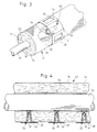
- FIG 4 a schematic and sectional view, illustrating the technique of draining an outer surface of a pipe which is insulated by means of a heat-insulating assembly circumferentially encircling the pipe, is shown.
- the insulating covering 12 circumferentially encircling the pipe 10 and comprising the insulating body 14 defining the inner cylindrical surface 16 and the outer cylindrical surface 18, at which the material-diffusion blocking barrier or foil 18 is provided is provided with a plurality of bores 42, in which water-removal devices constituted by water-removal devices implemented by the first embodiment 30 shown in figures 1 and 6 are received.
- the water-removal devices are preferably arranged at the lowermost position of the pipe 10, as, due to the gravitational force, any condensed water is caused to be accumulated at the lower side surface of the pipe 10. Therefore, a maximum water-removal effect is obtained provided the water-removal devices implemented in accordance with the teachings of the present invention are provided at the lowermost positions of the insulating covering 12 and extend to positions adjacent to the lower side surface of the pipe 10.
- the water-removal device implemented in accordance with the teachings of the present invention may be incorporated into the insulating body circumferentially encircling the tube to be insulated by means of the insulating body.
- FIG 2 a heat-insulating assembly according to the present invention is shown, in which annular disc-shaped water-removal elements constituting water-removal devices are incorporated.
- the pipe 10 is provided with an insulating covering composed of a plurality of annular, cylindrical insulating coverings 62, each comprising an insulating body 64 similar to the insulating body 14 shown in figures 1, 3 and 6, each of which insulating bodies defines an inner cylindrical surface arranged adjacent to or juxtaposed the outer cylindrical surface of the pipe 10 and an outer cylindrical surface together defining an overall outer cylindrical surface 68 of the heat-insulating assembly.
- a solid line 66 defines a line of separation between two adjacent segments 62.
- Two disc-shaped water-removal elements 70 constituted by annular discs of water-transport-allowing material are also shown in figure 2.
- the annular disc-shaped water-removal elements define an inner diameter, which is substantially equal to, still slightly smaller than the outer diameter of the pipe 10, and an outer diameter, which is larger than the outer diameter of the outer cylindrical surface 68. Consequently, the water-removal elements 70 each provides a tight fit around the outer cylindrical surface of the pipe 10 establishing a line contact between each of the elements 70 and the outer cylindrical surface of the pipe 10.
- each of the water-removal elements 70 provides a rim part protruding outwardly from the outer cylindrical surface 68 and defining an evaporation surface, from which condensed water transferred from the outer cylindrical surface of the pipe 10 and through the water-transport-allowing material of the water-removal element 70 in question is caused to evaporate, as the outwardly protruding rim segment of the water-removal element 70 in question is exposed to the ambient air.
- the outwardly protruding rim parts of the water-removal elements 70 may be taped to the outer cylindrical surface 68 of the insulating covering by means of a water-transparent tape or perforated tape or alternatively and preferably by means of a non-water-transparent tape, e.g. a perforated tape, which, however, provides uncovered parts of the outwardly protruding rim parts which uncovered parts are arranged bend along the outer cylindrical surface 68 of the insulating convering.
- the non-water transparent tape may further serve the purpose of sealing the separation between any two adjacent segments 62 of the insulating covering for preventing that water to any substantial extent penetrates into the separation or spacing between the two segments.
- FIG 5 a second or alternative embodiment of the heat-insulating assembly according to the present invention, comprising integral water-removal devices implemented in accordance with the teachings of the present invention, is shown.
- the pipe 10 is circumferentially encircled by the insulating covering 12, in which angularly spaced-apart, through-going bores 41, 42 and 43 are provided.
- a water-removal device implemented by the first embodiment 30 of the water-removal device according to the present invention, shown in figures 1 and 6, is received.
- the water-removal devices 30 shown in figure 5 are, however, fixated relative to the insulating covering 12, constituting integral components of a heat-insulating assembly provided with integral water-removal devices.
- the embodiment of the heat-insulating assembly shown in figure 5 is readily adaptable to insulating pipes, such as cold-water pipes or pipes through which e.g. a cooling or freezing fluid is transferred
- the water-removal device constituting a separate element as disclosed in figures 1, 3 and 6 and is readily adaptable to new installations or applications as well as renovation applications, i.e. applications by which an existing insulating covering is to be drained in accordance with the teachings of the present invention.
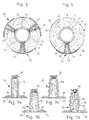
- the first embodiment 30 of the water-removal device according to the present invention discussed above with reference to figures 1, 3, 4, 5 and 6 may be implemented in accordance with various fixation and application techniques. These alternative techniques are illustrated in figures 7a, 7b, 7c and 7d.
- the conduit component of the water-removal device is constituted by a cylindrical tubular element 72, which defines a first open end, from which the material 36 protrudes, and an opposite, second open end, at which a flange component 74 is provided, which flange component serves the same purpose as the above-described flange components 34 and 52.
- the flange component 74 supports the foil 38 at an outer supporting surface thereof and is provided with an adhesive coating 76 at the opposite surface of the flange component, which surface is to be arranged in facial contact with the outer surface of the insulating covering, in which the water-removal device 30 is to be embedded.
- the water-removal device 30 shown in figure 7b differs from the water-removal device shown in figure 7a in that the cylindrical, tubular element 72 shown in figure 7b is substituted by a conical, tubular element 78 similar to the conduit component 32 discussed above.
- the water-removal device shown in figure 7b is also to be fixated relative to the insulating covering, in which the water-removal device is to be received and embedded, and provided with the adhesive coating 76.
- the adhesive coating 76 is omitted, whereas the conical, tubular element 78 is provided with outwardly protruding bards 80 serving the purpose of fixating the water-removal device 30 as the water-removal device 30 is introduced into a bore or aperture of the insulating covering, in which the water-removal device is to be received.
- FIGS. 7a, 7b and 7c of the water-removal device according to the present invention are to be introduced into a previously prepared bore or aperture of the insulating covering, in which the water-removal device is to be received.
- the water-removal device 30 shown in figure 7c is further modified by the addition of a perforating pin 82, which extends through the innerspace of the conical, tubular element 78 and projects from the first open end thereof together with the material 36.
- the perforating pin 82 is provided with a head 84, which is separable from the main body of the perforating pin 82 along a weakening line at the first open end of the conical, tubular element.
- the embodiment of the water-removal device 30 shown in figure 7d is, consequently, readily applicable in connection with an insulating covering.
- the insulating covering need not be prepared for the introduction of the water-removal device, as the water-removal device is simply forced into the insulating covering as the perforating pin 82 and the head thereof perforate the insulating covering.
- the head of the perforating pin contacts the outer cylindrical surface of the pipe or tube, adjacent to which the water-removal device is to be arranged, the head is broken from the main body of the perforating pin 82 along the above-mentioned weakening line, allowing the water-removal device to be forced into its intentional end position, in which the flange component 74 is brought into facial contact with the adjacent outer surface of the insulating covering.
- a novel technique of removing condensed water from the outer surface of the pipe 10 is disclosed.
- a rod 90 of a water-transport-allowing material, or preferably a capillary suction material is introduced into a through-going passage 86 extending through the insulating body 14 of the insulating covering 12 from the outer cylindrical surface 18 of the insulating covering 12 to the vicinity of the outer surface of the pipe 10.
- the rod 90 is preferably arranged in direct contact with the outer surface of the pipe 10.
- the rod 90 After the rod 90 has been introduced into the through-going passage 86 establishing direct contact with the outer surface of the pipe 10, the rod is cut off at the outer cylindrical surface 18 of the insulating covering 12, providing a free piece of the rod, which piece is shown in fig. 9 and designated the reference numeral 88.
- a foil 92 of water-transport-allowing material is wound round the insulating covering 12, establishing contact with the rod 90 so as to allow transfer of condensed water from the rod 90 to the foil 92 which serves the purpose as an evaporator body for evaporating the condensed water transferred to the foil 92 to the ambient air.
- the foil 92 is fixated relative to the insulating covering 92 by means of an adhesive tape 94.
- the foil 92 is arranged defining an overlap, however, the foil 92 may constitute a segment covering a part of the outer cylindrical surface 18 of the insulating covering 12, exclusively.
- the insulating covering is divided into two segments 62 similar to the segments 62 shown in fig. 2, which segments, however, may be provided by cutting the insulating covering 12 shown e.g. in figures 1, 3, 8, and 9 along a radial slit providing a through-going slit from the outer cylindrical surface of the insulating covering to the inner cylindrical surface of the insulating covering, which inner cylindrical surface is arranged juxtaposed the outer surface of the pipe 10.
- a lead or cord of a water-transport-allowing material is forced into the circumferential and through-going slit 66 providing a winding 96 encircling the outer surface of the pipe 10 and an outwardly protruding free end 98 of the lead or cord.
- the lead or cord comprising the winding 96 and the outwardly protruding free end 98, constitutes a water transport means similar to the rod 90 shown in figures 8 and 9 and the filling of the conduit component 30 of the first device 30 shown in fig. 1.
- the evaporator foil 92 also shown in figures 8 and 9 is arranged encircling the outer surface of the insulating body comprising the segments 62 and establishing contact with the lead or rod, the free end 98 of which projects or protrudes freely from the circumferential rim of the foil 92 as shown in fig. 11.
- the free end 98 of the lead or cord may in itself constitute an evaporator for evaporating condensed water transferred from the outer surface of the pipe 10 through the winding 96 to the free end, however, preferably communicates with the foil 92 which serves the purpose of providing an enlarged evaporator surface as compared to the evaporator surface of the free end 98 of the lead or cord.
- FIG 12 a diagramme is shown, illustrating the water-removal capability of the water-removal technique according to the present invention.
- a solid line curve illustrates the amount of water, as expressed in gram, which is accumulated within a mineral wool-insulating layer arranged circumferentially encircling a pipe, through which cold water is transferred, and which is provided with an outer aluminum foil coating, from the day of applying the insulation to the pipe.
- a dotted line curve similarly illustrates the amount of water accumulated within a foamed insulating layer applied to the very same pipe.
- a water-removal device constituted by a prototype implementation of the water-removal device according to the present invention, as shown in figures 1 and 6, was introduced into the mineral wool-insulating layer, resulting in a reduction of the amount of accumulated water from approximately 72g to approximately 32g after approximately 45 days. After the water-removal device had been applied, the amount of water accumulated within the mineral wool-insulating layer was reduced as compared to the amount of water accumulated within the foamed insulating layer.
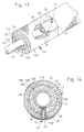
- FIG. 13 an alternative application of the first embodiment of the water-removal device according to the present invention described above with reference to figs. 1, 4, 5, and 6 is illustrated.
- the pipe 10 is insulated by means of a two-layer foamed insulating covering 112 defining an outer cylindrical surface 118 and an inner cylindrical surface 116 which is arranged adjacent to or juxtaposed to the cylindrical surface of the pipe 10.
- the two-layer foam 112 insulating covering 112 comprises an outer insulating foamed layer 114 and an inner insulating foamed layer 115 which are separated relative to one another along a separating surface defining a line of separation 113 shown in fig. 13.
- the two-layer foamed insulating covering 112 may further be provided with an outer protective and water-transport blocking barrier or foil provided at the outer cylindrical surface 118 and an inner water-transport blocking barrier or foil provided at the inner cylindrical surface 116.
- the two-layer foamed insulating covering 112 serves the same purpose as the insulating covering 12 discussed above with reference to fig. 1. Similar to the insulating covering 12 described above, the two-layer foamed insulating covering 112 is provided with a longitudinal cut 120 allowing the two-layer foamed insulating covering 112 to be arranged circumferentially encircling the pipe 10.
- the two-layer foamed insulating covering 112 is provided with two locking components 122 and 124 which are locked together in a seal 126 of a zipper-like configuration.
- burr-like sealing strips or adhesive sealing strips may be provided for assembling the two-layer foamed insulating covering 112 circumferentially encircling the pipe 10.
- a vertical sectional view thru the two-layer foamed insulating covering 112 and pipe 10 is shown further disclosing the interspace 44 also discussed above with reference to fig. 6 which interspace is defined between the inner cylindrical surface 116 of the two-layer foamed insulating covering 112 and the outer cylindrical surface of the pipe 10.
- the first embodiment of the water-removal device 30 according to the present invention is as is evident from figs. 13 and 14 arranged in a through-going bore or aperture 119 of the two-layer foamed insulating covering 112 and arranged so as to provide water-transport communication through the material 36 establishing contact with the outer cylindrical surface of the pipe 10 to the water-evaporation foil 38 of the device 30.
- the above described two-layer foamed insulating covering 112 may be substituted by a single layer foamed insulating covering which may further constitute an integral body which is not provided with any inner or outer protective and water-transport blocking barriers.
- the foamed insulating covering being a single layer, a two-layer or a multilayer structure may comprise closed cells or open cells.
- the above-described two-layer foamed insulating covering 112 may at the interspace between the two foamed layers 114 and 115 be provided with a water-transport blocking barrier or foil.
- the insulating covering is made from mineral wool and from the outer surface of the pipe and also from an inner layer of the insulating covering provided the insulating covering is made from foamed material.
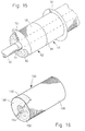
- Fig. 15 a slightly modified embodiment of the heat-insulating assembly according to the present invention described above with reference to Fig. 2 is shown.
- the embodiment shown in Fig. 15 differs from the embodiment shown in Fig. 2 in that the disc-shaped water removal elements 70 each defines an inner diameter which is somewhat smaller than the outer diameter of the pipe 10. Consequently, the water removal elements 70 each defines a turned end part 71 which is arranged in facial contact with the outer cylindrical surface of the pipe 10. By the provision of the turned end parts 71, a tight fit of the elements 70 around the pipe 10 is established.
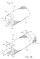
- a further embodiment of the heat-insulating assembly according to the present invention is shown designated the reference numeral 130 in its entirety.
- the embodiment shown in Fig. 16 constitutes a segment of an annular, cylidrical insulating covering to be arranged circumferentially encirling a pipe as will be described in greater details below with reference to Figs. 18 and 19.
- the embodiment 130 comprises an annular, cylindrical segment of an insulating body 132 defining an inner cylindrical surface 134 to be arranged adjacent to or juxtaposed the cylindrical surface of the above-mentioned pipe and defining an outer cylindrical surface 136.
- the outer cylindrical surface is covered by a water-barrier foil.
- the insulating body 132 defines an annular end surface which is covered by a layer 138 of a hygroscopic paint which constitutes a means for transport of water from the outer cylindrical surface or the pipe on which the segment 130 is arranged in accordance with the teachings of the present invention.
- a further layer 140 of the hygroscopic paint is applied for providing a means for evaporation of water transferred to the layer 140 through the layer 138.
- the layer 138 provides a line contact with a part of the outer cylindrical surface of the pipe on which the segment 130 is arranged.
- a slightly modified embodiment as compared to the embodiment described above with reference to Fig. 16 of the heat-insulating assembly is shown designated the reference numeral 130' in its entirety.
- the embodiment 130' differs from the above described embodiment 130 in that an additional layer 142 of the hygroscopic paint is applied at the inner cylindrical surface 134 of the insulating body 132.
- the additional layer 142 is provided for establishing a surface contact with the outer cylindrical surface of the above-mentioned pipe on which the segment 130' is arranged.
- the layers 138 and 140 and optionally the additional layer 142 are preferably applied in a single paint application step by spraying or transferring the hygroscopic paint to the insulating body 132 by means of an applicator of any appropriate structure.
- the layers 138, 140 and 142 may simply be provided by partly immersing one end of the insulating body 132 into the hygroscopic paint from which the layers 138, 140 and 142 are provided.
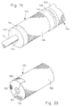
- the segment 130 is arranged encircling the above-described tube 10 together with an additional segment 230 which may be of a structure identical to the structure of the segment 130.
- the segment 230 defines an ounter cylindrical surface 236 which corresponds to the outer cylindrical surface 156 of the segment 130 and which is provided with a layer 240 of the hygroscopic paint similar to the layer 140 of the layer 130.
- the segments 130 and 230 are preferably arranged closely adjacent one another in order to eliminate that a gap is established between the annular end surfaces of the segments 130 and 230.
- a junction between the segments 130 and 230 is sealed by means of a tape constituting a vapor-barrier foil which is provided with partly exposing the layer 240 of the hygroscopic paint of the segment.
- the tape 144 is a tape composed of two parts one of which is provided with perforations arranged partly exposing the layer 240 of the hygroscopic paint and one of which is arranged sealing the junction between the segments 130 and 230 preventing that vapor or liquid may permeate into the space inevitably provided between the annular end surfaces of the segments 130 and 230 which end surfaces are arranged juxtaposed one another.
- the embodiments 130 and 130' may be modified in that the outer vapor-barrier foil 136 may also be applied to the annular end surfaces of the insulating body 132 providing a vapor-barrier closure of the annular end surfaces.
- the outer vapor-barrier foil 136 may also be applied to the annular end surfaces of the insulating body 132 providing a vapor-barrier closure of the annular end surfaces.
- only one of the annular end surfaces of the annular cylindrical insulating bodies is provided with a layer of the hygroscopic paint communicating with the outer and optionally the inner layers of the hygroscopic paint.
- the hygroscopic paint or any other water-transport-allowing material may be applied at both end surfaces of the insulating body of the heat-insulating assembly.
- a further embodiment of the heat-insulating assembly according to the present invention is shown, designated the reference numeral 150 in its entirety.
- the embodiment 150 constitutes a segment similar to the segments 130 and 130' described above with reference to Figs. 16 and 17, however, differing from the above described embodiments 130 and 130' in that the annular end surfaces of the annular cylindrical insulating body of the embodiment is covered by a vapor-barrier foil 152 which is integrally connected to an outer circumferential encircling vapor-barrier foil similar to the foil 136 and designated the reference numeral 156.
- the annular cylindrical insulating body defines an outer cylindrical surface and an inner cylindrical surface 154.
- a water-transport-allowing foil 158 is applied, which foil is integrally connected to a foil layer 160 provided at the outer cylindrical surface 156 of the segment 150.
- the segment 150 is arranged on the pipe 10 described above along with a further segment 250 which may be of a structure identical to the structure of the segment 150 and defines an outer cylindrical surface 256 similar to the surface 156 of the segment 150.
- a foil 260 of the segment 260 constitutes an evaporator similar to the foil 160 of the segment 150.
- the segments 150 and 250 are, like the above described segments 130 and 230, as shown in Fig. 19 preferably provided with a sealing constituted by the above described tape 144 provided with the perforations 146 which are arranged partly exposing the foil 260 in order to allow that water may evaporate from the evaporator 260.
- the conduit component 32 was constituted by a tubular segment of a PVC tube of a length of 18 mm having an outer diameter of 12 mm and an inner diameter of 8 mm.
- the flange component 34 was cast from PVC of a thickness of approximately 2 mm and measured 30 mm x 30 mm.
- the water-transport-allowing material received within the conduit component 32 was constituted by approximately 1 g of the viscose-based non-woven material.
- the foil 38 was made from the same water-transport-allowing material as the conduit component 32 of an amount of approximately 1-2 g and measuring 30 mm x 100 mm.
- the water-transport-allowing material which is preferably a capillary suction material may be provided from any material fulfilling the purpose as discussed above and may e.g. comprise cellulose fibers, non-woven or woven glass or polymer-based non-woven materials such as polypropylene felt materials or any other similar or equivalent material.
- the water-transport-allowing material is preferably a material allowing a transport of water through the material without accumulating an extreme amount of water within the material.
- the hygroscopic paint may be manufactured from the following components: binder 5-10% clay 30-50% water 40-55%
- the binder may be constituted by a polyvinyl acetate, a polyester dispersion or a water dispersion of natural rubber.
- additional components preferably less than 2%, at the most 5% of the paint may be included. All percentages by weight.
- the clay of the paint constitutes a capillary suction material, and the particle size of clay is 50% ⁇ 1 ⁇ . Fungicides may additionally be included in the paint.
- the height of rise of water may amount to 0-500 mm, such as 50-250 mm.
- the paint is preferably applied as the layers 138, 140, and 142 as shown in Figs. 16-19, in an amount of 50-1000 g/m 2 , preferably 100-500 g/m 2 .
- the inner surface of the heat insulating covering is illustrated as an insulating covering arranged a small distance from the outer periphery of the pipe.
- the heat insulating covering is arranged in closer contact with the outer surface of the pipe so as to eliminate any space between the inner cylindrical surface of the heat insulating covering and the outer cylindrical surface of the pipe and further reduce the transport of water along the outer cylindrical surface of the pipe.
Landscapes
- Engineering & Computer Science (AREA)
- General Engineering & Computer Science (AREA)
- Mechanical Engineering (AREA)
- Thermal Insulation (AREA)
- Processing Of Terminals (AREA)
- Drying Of Gases (AREA)
- Electrical Discharge Machining, Electrochemical Machining, And Combined Machining (AREA)
- Motor Or Generator Cooling System (AREA)
Abstract
Description
| binder | 5-10% |
| clay | 30-50% |
| water | 40-55% |
Claims (34)
- A heat-insulating assembly (12, 62, 112, 130, 130', 150) for insulating a surface of a body (10) relative to the ambient air, said surface of said body (10) having a surface temperature at or below the dew point of the ambient air, comprising:a heat-insulating layer (14; 64; 132; 138; 152; 114, 115) defining an insulating body covering said surface of said body (10), said insulating body (14; 64; 132; 138; 152; 114, 115) defining an inner surface (16, 116, 134, 154) and an outer surface (18, 68, 118, 136, 156), said inner surface (16, 116, 134, 154) being arranged juxtaposed said surface of said body (10),a water-removal means (36, 70, 90, 138, 158) of a water-transport-allowing material, said water-removal means (36, 70, 90, 138, 158) being embedded within a through-going passage of said insulating body (14; 64; 132; 138; 152; 114, 115) and being exposed at said inner surface (16, 116, 134, 154) of said insulating body (14; 64; 132; 138; 152; 114, 115) so as to contact said water-removal means (36, 70, 90, 138, 158) embedded within said through-going passage with said surface of said body (10) in a point contact or a line contact for allowing transfer of condensed water from said surface of said body (10) to said water-transport-allowing material of said water-removal means (36, 70, 90, 138, 158), anda water evaporation means (38, 98) of a water-transport-allowing material, said evaporation means (38, 98) defining an exposed evaporation surface and being arranged at said outer surface (18, 68, 118, 136, 156) of said insulating body (10) and communicating with said water-removal means (36, 70, 90, 138, 158) so as to allow transfer of water from said water-removal means (36, 70, 90, 138, 158) to said evaporation means (38, 98), said exposed evaporation surface of said evaporation means (38, 98) being exposed to the ambient air.
- The heat-insulating assembly (12, 62, 112, 130, 130', 150) according to Claim 1, said body (10) being a tubular body, said heat-insulating layer (14; 64; 132; 138; 152; 114, 115) defining an annular insulating body circumferentially encircling said tubular body (10), and said inner surface (16, 116, 134, 154) and said outer surface (18, 68, 118, 136, 156) being cylindrical surfaces and said inner cylindrical surface (16, 116, 134, 154) being arranged juxtaposed said surface of said tubular body (10).
- The heat-insulating assembly (12, 62, 112, 130, 130', 150) according to any of the Claims 1 or 2, said water-transport-allowing material of said water-removal means (36, 70, 90, 138, 158) being a capillary suction material.
- The heat-insulating assembly (12, 62, 112, 130, 130', 150) according to any of the Claims 1-3, said water-transport-allowing material of said water evaporation means (38, 98) being a capillary suction material.
- The heat-insulating assembly (12, 62, 112, 130, 130', 150) according to any of the Claims 1-4, further comprising a vapor barrier layer arranged at said outer surface (18, 68, 118, 136, 156) of said insulating body (14; 64; 132; 138; 152; 114, 115).
- The heat-insulating assembly (12, 62, 112, 130, 130', 150) according to any of the Claims 1-5, said water-transport-allowing material of said water-removal means (36, 70, 90, 138, 158) protruding from said inner surface (16, 116, 134, 154) of said insulating body (14; 64; 132; 138; 152; 114, 115).
- The heat-insulating assembly (62) according to any of the Claims 2-6, said water-removal means (70) being constituted by an annular disc (70) of said water-transport-allowing material, said annular disc (70) being embedded between two cylindrical segments (62) of said annular insulating body (64), said cylindrical segments (62) together defining said through-going passage of said insulating body (14; 64; 132; 138; 152; 114, 115).
- The heat-insulating assembly (62) according to Claim 7, said evaporation means being constituted by an annular segment (62) of said annular disc-shaped water-removal means (70) protruding from said outer cylindrical surface (18, 68, 118, 136, 156) of said annular insulating body (64).
- The heat-insulating assembly (62) according to any of the Claims 2-6, said water-removal means being constituted by a cord (96) of said water-transport-allowing material, said cord (96) being arranged circumferentially encircling said tubular body (10) and being embedded between two cylindrical segments (62) of said annular insulating body (64), said cylindrical segments (62) together defining said through-going passage of said insulating body (14; 64; 132; 138; 152; 114, 115).
- The heat-insulating assembly (62, 130, 130') according to Claim 9, said evaporation means (38, 98) being constituted by a foil (18) of said water-transport-allowing material, said foil (18) being arranged circumferentially encircling said outer cylindrical surface (18, 68, 118, 136, 156) of said annular insulating body (14; 64; 132; 138; 152; 114, 115).
- The heat-insulating assembly (130, 130') according to any of the Claims 2-6, said water-removal means being constituted by a layer (138) of a hygroscopic paint applied to an annular end surface part of a cylindrical segment of said annular insulating body (132), said annular end surface part of said cylindrical segment together with an annular end surface part of an adjacent cylindrical segment of said annular insulating body (132) defining said through-going passage of said insulating body (14; 64; 132; 138; 152; 114, 115).
- The heat-insulating assembly (130, 130') according to Claim 11, said evaporation means being constituted by a further layer (140) of said hygroscopic paint applied to said outer surface (136) part of said insulating body (132).
- The heat-insulating assembly (130, 130') according to Claim 12, said layer (138) of said hygroscopic paint applied to said end surface part of said segment and said further layer (140) of said hygroscopic paint constituting an integral layer of said hygroscopic paint.
- The heat-insulating assembly (130, 130') according to any of the Claims 1-13, further comprising a perforated foil (144) of a vapor barrier material applied to said water evaporation means and exposing said water evaporation means through perforations of said perforated foil (144).
- The heat-insulating assembly (12, 62, 112, 130, 130', 150) according to Claim 1, said water-removal means being included in a device (30, 50, 88, 96) for removing condensed water from said surface of said body (10), said heat-insulating layer (14; 64; 132; 152; 114, 115) defining an assembly thickness, and said device (30, 50, 88, 96) comprising:a conduit means (32, 78, 86) of a tubular configuration and defining a inner through-going passage, said conduit means (32, 78, 86) having a length substantially equal to said assembly thickness, and said conduit means (32, 78, 86) defining opposite first and second open ends,a plug means (36) of a water-transport-allowing material, said plug means (36) being received within said conduit means (32, 78, 86) and constituting a filling of said inner through-going passage, said water-transport-allowing material being exposed at said first open end of said conduit means (32, 78, 86),a water evaporation means (38, 98) of a water-transport-allowing material, said evaporation means (38, 98) defining an exposed evaporation surface and being arranged at said second open end of said conduit means (32, 78, 86), and said evaporation means (38, 98) communicating with said plug means (36) at said second open end of said conduit means (32, 78, 86) so as to allow transfer of water from said plug means (36) to said evaporation means (38, 98), andsaid conduit means (32, 78, 86) being received within said through-going passage (42) of said heat-insulating layer (14; 64; 132; 138; 152; 114, 115) and fastened relative thereto in a position in which said first open end of said conduit means (32, 78, 86) is positioned adjacent to said surface of said body (10), so as to allow transfer of condensed water from said surface of said body (10) to said water-transport-allowing material of said plug means (36) being exposed at said first open end of said conduit means (32, 78, 86), and in which position said exposed evaporation surface of said evaporation means (38, 98) is positioned at said outer surface (18, 68, 118, 136, 156) of said heat-insulating layer (14; 64; 132; 138; 152; 114, 115) and is exposed to the ambient air.
- The heat-insulating assembly (12, 62, 112, 130, 130', 150) according to Claim 15, said water-transport-allowing material of said plug means (36) being a capillary suction material.
- The heat-insulating assembly (12, 62, 112, 130, 130', 150) according to any of the Claims 15 or 16, said water-transport-allowing material of said water evaporation means (38, 98) being a capillary suction material.
- The heat-insulating assembly (12, 62, 112, 130, 130', 150) according to any of the Claims 15-17, further comprising a vapor barrier layer arranged at said outer surface (18, 68, 118, 136, 156), of said heat-insulating layer (14; 64; 132; 138; 152; 114, 115).
- The heat-insulating assembly (12, 62, 112, 130, 130', 150) according to any of the Claims 29-32, said water-transport-allowing material of said plug means (36) protruding from said first open end of said conduit means (32, 78, 86).
- The heat-insulating assembly (12, 62, 112, 130, 130', 150) according to any of the Claims 15-19, said conduit means (32, 78, 86) comprising a flange means (34, 52) at said second open end thereof, said flange means (34, 52) defining a support surface for supporting said evaporation means (38, 88, 98).
- The heat-insulating assembly (12, 62, 112, 130, 130', 150) according to Claim 20, said support surface being provided with an adhesive layer (76) for adhering said evaporation means (38, 98) to said support surface of said flange means (34, 52).
- The heat-insulating assembly (12, 62, 112, 130, 130', 150) according to any of the Claims 20 or 21, said flange means (34, 52) being of a curved configuration.
- The heat-insulating assembly (12, 62, 112, 130, 130', 150) according to Claim 20, said flange means (34, 52) constituting a cylindrical segment.
- The heat-insulating assembly (12, 62, 112, 130, 130', 150) according to Claim 24, said circular, cylindrical segment defining an arch of the order of 40°-240°, such as an arch of the order of 40°-60° or of the order of 180°-240°, preferably approximately 60° or approximately 200°-220°.
- The heat-insulating assembly (12, 62, 112, 130, 130', 150) according to any of the Claims 15-24, said heat-insulating assembly (12, 62, 112, 130, 130', 150) comprising a plurality of devices (30, 50, 88, 90, 96) for removing condensed water from said surface of said body (10).
- The heat-insulating assembly (12, 62, 112, 130, 130', 150) according to Claim 25, said heat-insulating layer (14; 64; 132; 138; 152; 114, 115) defining an annular insulating body (14; 64; 132; 138; 152; 114, 115) circumferentially encircling said body (10) being a tubular body (10), said annular insulating body (14; 64; 132; 138; 152; 114, 115) defining an inner cylindrical surface (16, 116, 134, 154) and an outer cylindrical surface (18, 68, 118, 136, 156), said inner cylindrical surface (16, 116, 134, 154) being arranged juxtaposed said surface of said tubular body (10), said plurality of devices (30, 50, 88, 90, 96) comprising sets of devices (30, 50, 88, 90, 96) being arranged circumferentially spaced apart at said outer cylindrical surface (18, 68, 118, 136, 156) of said annular insulating body (14; 64; 132; 138; 152; 114, 115), and said sets being spaced apart longitudinally along said outer cylindrical surface (18, 68, 118, 136, 156) of said annular insulating body (14; 64; 132; 138; 152; 114, 115).
- A method of removing condensed water from a surface of a body (10) having a surface temperature at or below the dew point of the ambient air, said surface being insulated relative to the ambient air by means of a heat-insulating assembly (12, 62, 112, 130, 130', 150) defining an inner surface (16, 116, 134, 154) arranged juxtaposed said surface of said body (10) and an outer surface (18, 68, 118, 136, 156), exposed to the ambient air, said method comprising:providing a through-going passage extending through said heat-insulating assembly (12, 62, 112, 130, 130', 150) defining first and second open ends at said inner and outer surfaces (18, 68, 118, 136, 156), respectively, of said heat-insulating assembly (12, 62, 112, 130, 130', 150),arranging a water-removal means (36, 70, 90, 138, 158) of a water-transport-allowing material within said through-going passage constituting a filling thereof, said water-transport-allowing material being exposed at said first open end of said through-going passage, so as to contact said water-removal means (36, 70, 90, 138, 158) embedded within said through-going passage with said surface of said body (10) in a point contact or a line contact for transfer of condensed water from said surface of said body (10) to said water-transport-allowing material of said water removal means (36, 70, 90, 138, 158), andarranging a water evaporation means (38, 98) of a water-transport-allowing material defining an exposed evaporation surface at said second open end of said through-going passage, so as to establish communication between said water-removal means (36, 70, 90, 138, 158) and said evaporation means (38, 98) at said second open end of said through-going passage, and so as to allow transfer of water from said water-removal means (36, 70, 90, 138, 158) to said evaporation means (38, 98), said exposed evaporation surface of said water evaporation means (38, 98) being exposed to the ambient air for evaporating water to the ambient air.
- The method of Claim 27, said water-transport-allowing material of said water-removal means (36, 70, 90, 138, 158) being a capillary suction material.
- The method according to any of the Claims 27 or 28, said water-transport-allowing material of said water evaporation means (38, 98) being a capillary suction material.
- The method according to any of the Claims 27-29, said body (10) being tubular and said heat-insulating assembly (62, 112, 130, 130', 150) defining an annular insulating body (64; 132; 138; 152; 114, 115) circumferentially encircling said tubular body (10), said annular insulating body (64; 132; 138; 152; 114, 115) defining an inner cylindrical surface (16, 116, 134, 154) and an outer cylindrical surface (18, 68, 118, 136, 156), said inner cylindrical surface (16, 116, 134, 154) being arranged juxtaposed the surface of the tubular body (10), and said outer cylindrical surface (18, 68, 118, 136, 156) being exposed to the ambient air, said through-going passage constituting a through-going circumferential slit (66) extending through said insulating body (14; 64; 132; 138; 152; 114, 115) from said outer cylindrical surface (18, 68, 118, 136, 156) to said inner cylindrical surface (16, 116, 134, 154), and said water-removal means being constituted by an elongated and flexible water-transport means (96) of a water-transport-allowing material to be arranged within said circumferential slit (66) encircling said surface of the tubular body (10) and extending from said inner cylindrical surface (16, 116, 134, 154) of said annular insulating body (64; 132; 138; 152; 114, 115) to said outer cylindrical surface (18, 68, 118, 136, 156) of said annular insulating body (64; 132; 138; 152; 114, 115).
- The method according to any of the Claims 27-29, said body (10) being tubular and said heat-insulating assembly (12, 62, 112, 130, 130', 150) defining an annular insulating body (10) circumferentially encircling said tubular body (10), said annular insulating body (14; 64; 132; 138; 152; 114, 115) defining an inner cylindrical surface (16, 116, 134, 154) and an outer cylindrical surface (18, 68, 118, 136, 156), said inner cylindrical surface (16, 116, 134, 154) being arranged juxtaposed said surface of said tubular body (10), and said outer cylindrical surface (18, 68, 118, 136, 156) being exposed to the ambient air, said method comprising:said through-going passage constituting a through-going circumferential slit extending through said insulating body (14; 64; 132; 138; 152; 114, 115) from said outer cylindrical surface (18, 68, 118, 136, 156) to said inner cylindrical surface (16, 116, 134, 154), so as to divide said annular insulating body (14; 64; 132; 138; 152; 114, 115) into two segments (136, 236) having juxtaposed end surface parts,said water-removal means being constituted by a layer of a hygroscopic paint (138) to be applied to at least one of said end surface parts of said segments, said layer extending from said inner cylindrical surface (16, 116, 134, 154) of said annular insulating body (14; 64; 132; 138; 152; 114, 115) to said outer cylindrical surface (18, 68, 118, 136, 156) of said annular insulating body (14; 64; 132; 138; 152; 114, 115) and said water evaporation means being constituted by a further layer of a hygroscopic paint (140) to be applied to said outer cylindrical surface (18, 68, 118, 136, 156) of said annular insulating body (14; 64; 132; 138; 152; 114, 115), said further layer (140) defining an exposed evaporation surface at said outer cylindrical surface (18, 68, 118, 136, 156) of said annular insulating body (14; 64; 132; 138; 152; 114, 115).
- The method according to Claim 31, said further layer (140) being applied to one of said segments or both segments of said annular insulating body (64; 132; 138; 152; 114, 115).
- The method according to any of the Claims 31 or 32, said layer (138) of said hygroscopic paint and said further layer (140) of said hygroscopic paint being constituted by a single integral layer.
- The method according to any of the Claims 31-33, a perforated vapor barrier foil (144) further being arranged covering said further layer (140) and exposing said water evaporation means (98) through perforations (146) of said perforated foil (144).
Applications Claiming Priority (7)
| Application Number | Priority Date | Filing Date | Title |
|---|---|---|---|
| DK1082/92 | 1992-08-31 | ||
| DK108292 | 1992-08-31 | ||
| DK108292A DK108292D0 (en) | 1992-08-31 | 1992-08-31 | METHOD AND APPARATUS FOR INSULATION |
| DK141392 | 1992-11-24 | ||
| DK141392A DK141392D0 (en) | 1992-11-24 | 1992-11-24 | METHOD AND APPARATUS FOR INSULATION |
| DK1413/92 | 1992-11-24 | ||
| PCT/DK1993/000281 WO1994005947A1 (en) | 1992-08-31 | 1993-08-27 | Method and apparatus for insulating |
Publications (2)
| Publication Number | Publication Date |
|---|---|
| EP0660910A1 EP0660910A1 (en) | 1995-07-05 |
| EP0660910B1 true EP0660910B1 (en) | 1998-11-04 |
Family
ID=26065194
Family Applications (1)
| Application Number | Title | Priority Date | Filing Date |
|---|---|---|---|
| EP93919035A Expired - Lifetime EP0660910B1 (en) | 1992-08-31 | 1993-08-27 | Method and apparatus for insulating |
Country Status (8)
| Country | Link |
|---|---|
| EP (1) | EP0660910B1 (en) |
| AT (1) | ATE173072T1 (en) |
| AU (1) | AU4944993A (en) |
| CA (1) | CA2143450A1 (en) |
| CZ (1) | CZ47395A3 (en) |
| DE (1) | DE69321969T2 (en) |
| SK (1) | SK22395A3 (en) |
| WO (1) | WO1994005947A1 (en) |
Families Citing this family (5)
| Publication number | Priority date | Publication date | Assignee | Title |
|---|---|---|---|---|
| CZ202896A3 (en) * | 1994-01-14 | 1997-01-15 | Rockwool Int | Insulation process and apparatus for making the same |
| JPH11515078A (en) * | 1995-10-30 | 1999-12-21 | ハイグロウィック−インターナショナル アーペーエス | Insulation system and method for providing an insulation system to a pipe or vessel (insulation system) |
| GB9717482D0 (en) | 1997-08-18 | 1997-10-22 | Rockwool Int | Roof and wall cladding |
| GB9717484D0 (en) | 1997-08-18 | 1997-10-22 | Rockwool Int | Roof and wall cladding |
| SE525985C2 (en) * | 2003-10-17 | 2005-06-07 | Saint Gobain Isover Ab | Insulation systems for technical installations |
Family Cites Families (1)
| Publication number | Priority date | Publication date | Assignee | Title |
|---|---|---|---|---|
| DK164303C (en) * | 1990-05-14 | 1992-10-19 | Vik Consult | INSULATION FOR A PIPE OR CHANNEL WITH A RELATIVE LOW SURFACE TEMPERATURE AND PROCEDURE FOR PREPARING THE INSULATION |
-
1993
- 1993-08-27 CA CA002143450A patent/CA2143450A1/en not_active Abandoned
- 1993-08-27 AU AU49449/93A patent/AU4944993A/en not_active Abandoned
- 1993-08-27 CZ CZ95473A patent/CZ47395A3/en unknown
- 1993-08-27 EP EP93919035A patent/EP0660910B1/en not_active Expired - Lifetime
- 1993-08-27 WO PCT/DK1993/000281 patent/WO1994005947A1/en not_active Ceased
- 1993-08-27 AT AT93919035T patent/ATE173072T1/en not_active IP Right Cessation
- 1993-08-27 DE DE69321969T patent/DE69321969T2/en not_active Expired - Fee Related
- 1993-08-27 SK SK223-95A patent/SK22395A3/en unknown
Also Published As
| Publication number | Publication date |
|---|---|
| SK22395A3 (en) | 1995-07-11 |
| CZ47395A3 (en) | 1995-12-13 |
| WO1994005947A1 (en) | 1994-03-17 |
| ATE173072T1 (en) | 1998-11-15 |
| DE69321969D1 (en) | 1998-12-10 |
| CA2143450A1 (en) | 1994-03-17 |
| DE69321969T2 (en) | 1999-04-01 |
| EP0660910A1 (en) | 1995-07-05 |
| AU4944993A (en) | 1994-03-29 |
Similar Documents
| Publication | Publication Date | Title |
|---|---|---|
| US5520009A (en) | Method and apparatus for insulating | |
| US5690147A (en) | Method and apparatus for insulating | |
| US5441083A (en) | Insulation system for conduit or container wherein inner and outer water-absorbing layers connect through slot in intermediate heat-insulating layer | |
| EP1482235B1 (en) | Coated fibrous pipe insulation system | |
| KR101129761B1 (en) | Pipe shell for technical installations | |
| EP1259751B1 (en) | Unitary vapor retarder for chilled pipe insulation | |
| US6026863A (en) | Insulation system and a method of providing an insulation system on a pipe or a container ("insulation system") | |
| JP5993823B2 (en) | Insulation cover device and method of constructing insulation cover device | |
| EP0660910A1 (en) | Method and apparatus for insulating | |
| JP5986672B2 (en) | Insulation cover device construction method | |
| US10774976B2 (en) | Systems and methods for insulating a pipe with a pre-applied vapor-barrier stop | |
| US9394684B1 (en) | Method and apparatus for an improved air barrier system | |
| GB2159912A (en) | Pipe insulation | |
| EP2069679B1 (en) | Adhesive tape for sealing a joint in an insulation system, and method for sealing such a joint | |
| JPH08219371A (en) | Insulation duct |
Legal Events
| Date | Code | Title | Description |
|---|---|---|---|
| PUAI | Public reference made under article 153(3) epc to a published international application that has entered the european phase |
Free format text: ORIGINAL CODE: 0009012 |
|
| 17P | Request for examination filed |
Effective date: 19950218 |
|
| AK | Designated contracting states |
Kind code of ref document: A1 Designated state(s): AT BE DE DK ES FR GB IT NL SE |
|
| 17Q | First examination report despatched |
Effective date: 19951130 |
|
| GRAG | Despatch of communication of intention to grant |
Free format text: ORIGINAL CODE: EPIDOS AGRA |
|
| GRAG | Despatch of communication of intention to grant |
Free format text: ORIGINAL CODE: EPIDOS AGRA |
|
| GRAH | Despatch of communication of intention to grant a patent |
Free format text: ORIGINAL CODE: EPIDOS IGRA |
|
| GRAH | Despatch of communication of intention to grant a patent |
Free format text: ORIGINAL CODE: EPIDOS IGRA |
|
| GRAA | (expected) grant |
Free format text: ORIGINAL CODE: 0009210 |
|
| AK | Designated contracting states |
Kind code of ref document: B1 Designated state(s): AT BE DE DK ES FR GB IT NL SE |
|
| PG25 | Lapsed in a contracting state [announced via postgrant information from national office to epo] |
Ref country code: SE Free format text: THE PATENT HAS BEEN ANNULLED BY A DECISION OF A NATIONAL AUTHORITY Effective date: 19981104 Ref country code: IT Free format text: LAPSE BECAUSE OF FAILURE TO SUBMIT A TRANSLATION OF THE DESCRIPTION OR TO PAY THE FEE WITHIN THE PRE;WARNING: LAPSES OF ITALIAN PATENTS WITH EFFECTIVE DATE BEFORE 2007 MAY HAVE OCCURRED AT ANY TIME BEFORE 2007. THE CORRECT EFFECTIVE DATE MAY BE DIFFERENT FROM THE ONE RECORDED.SCRIBED TIME-LIMIT Effective date: 19981104 Ref country code: ES Free format text: THE PATENT HAS BEEN ANNULLED BY A DECISION OF A NATIONAL AUTHORITY Effective date: 19981104 Ref country code: BE Free format text: LAPSE BECAUSE OF FAILURE TO SUBMIT A TRANSLATION OF THE DESCRIPTION OR TO PAY THE FEE WITHIN THE PRESCRIBED TIME-LIMIT Effective date: 19981104 Ref country code: AT Free format text: LAPSE BECAUSE OF FAILURE TO SUBMIT A TRANSLATION OF THE DESCRIPTION OR TO PAY THE FEE WITHIN THE PRESCRIBED TIME-LIMIT Effective date: 19981104 |
|
| REF | Corresponds to: |
Ref document number: 173072 Country of ref document: AT Date of ref document: 19981115 Kind code of ref document: T |
|
| REF | Corresponds to: |
Ref document number: 69321969 Country of ref document: DE Date of ref document: 19981210 |
|
| PG25 | Lapsed in a contracting state [announced via postgrant information from national office to epo] |
Ref country code: DK Free format text: LAPSE BECAUSE OF FAILURE TO SUBMIT A TRANSLATION OF THE DESCRIPTION OR TO PAY THE FEE WITHIN THE PRESCRIBED TIME-LIMIT Effective date: 19990204 |
|
| ET | Fr: translation filed | ||
| PG25 | Lapsed in a contracting state [announced via postgrant information from national office to epo] |
Ref country code: GB Free format text: LAPSE BECAUSE OF NON-PAYMENT OF DUE FEES Effective date: 19990827 |
|
| PLBE | No opposition filed within time limit |
Free format text: ORIGINAL CODE: 0009261 |
|
| STAA | Information on the status of an ep patent application or granted ep patent |
Free format text: STATUS: NO OPPOSITION FILED WITHIN TIME LIMIT |
|
| 26N | No opposition filed | ||
| GBPC | Gb: european patent ceased through non-payment of renewal fee |
Effective date: 19990827 |
|
| PGFP | Annual fee paid to national office [announced via postgrant information from national office to epo] |
Ref country code: FR Payment date: 20000811 Year of fee payment: 8 |
|
| PG25 | Lapsed in a contracting state [announced via postgrant information from national office to epo] |
Ref country code: FR Free format text: LAPSE BECAUSE OF NON-PAYMENT OF DUE FEES Effective date: 20020430 |
|
| REG | Reference to a national code |
Ref country code: FR Ref legal event code: ST |
|
| PGFP | Annual fee paid to national office [announced via postgrant information from national office to epo] |
Ref country code: NL Payment date: 20050803 Year of fee payment: 13 |
|
| PG25 | Lapsed in a contracting state [announced via postgrant information from national office to epo] |
Ref country code: NL Free format text: LAPSE BECAUSE OF NON-PAYMENT OF DUE FEES Effective date: 20070301 |
|
| NLV4 | Nl: lapsed or anulled due to non-payment of the annual fee |
Effective date: 20070301 |
|
| PGFP | Annual fee paid to national office [announced via postgrant information from national office to epo] |
Ref country code: DE Payment date: 20070823 Year of fee payment: 15 |
|
| PG25 | Lapsed in a contracting state [announced via postgrant information from national office to epo] |
Ref country code: DE Free format text: LAPSE BECAUSE OF NON-PAYMENT OF DUE FEES Effective date: 20090303 |