EP0659510B1 - Tool component - Google Patents
Tool component Download PDFInfo
- Publication number
- EP0659510B1 EP0659510B1 EP94309542A EP94309542A EP0659510B1 EP 0659510 B1 EP0659510 B1 EP 0659510B1 EP 94309542 A EP94309542 A EP 94309542A EP 94309542 A EP94309542 A EP 94309542A EP 0659510 B1 EP0659510 B1 EP 0659510B1
- Authority
- EP
- European Patent Office
- Prior art keywords
- recess
- interface
- tool component
- substrate
- component according
- Prior art date
- Legal status (The legal status is an assumption and is not a legal conclusion. Google has not performed a legal analysis and makes no representation as to the accuracy of the status listed.)
- Expired - Lifetime
Links
- 239000000758 substrate Substances 0.000 claims description 35
- 239000000463 material Substances 0.000 claims description 15
- 238000005520 cutting process Methods 0.000 claims description 12
- 229910003460 diamond Inorganic materials 0.000 claims description 10
- 239000010432 diamond Substances 0.000 claims description 10
- 239000002245 particle Substances 0.000 claims description 4
- 239000002131 composite material Substances 0.000 description 10
- 238000005553 drilling Methods 0.000 description 6
- 229910052582 BN Inorganic materials 0.000 description 4
- PZNSFCLAULLKQX-UHFFFAOYSA-N Boron nitride Chemical compound N#B PZNSFCLAULLKQX-UHFFFAOYSA-N 0.000 description 4
- 229910052751 metal Inorganic materials 0.000 description 4
- 239000002184 metal Substances 0.000 description 4
- 239000011230 binding agent Substances 0.000 description 3
- XEEYBQQBJWHFJM-UHFFFAOYSA-N Iron Chemical compound [Fe] XEEYBQQBJWHFJM-UHFFFAOYSA-N 0.000 description 2
- PXHVJJICTQNCMI-UHFFFAOYSA-N Nickel Chemical compound [Ni] PXHVJJICTQNCMI-UHFFFAOYSA-N 0.000 description 2
- 230000015572 biosynthetic process Effects 0.000 description 2
- 238000000034 method Methods 0.000 description 2
- 238000003801 milling Methods 0.000 description 2
- QIJNJJZPYXGIQM-UHFFFAOYSA-N 1lambda4,2lambda4-dimolybdacyclopropa-1,2,3-triene Chemical compound [Mo]=C=[Mo] QIJNJJZPYXGIQM-UHFFFAOYSA-N 0.000 description 1
- GJNGXPDXRVXSEH-UHFFFAOYSA-N 4-chlorobenzonitrile Chemical compound ClC1=CC=C(C#N)C=C1 GJNGXPDXRVXSEH-UHFFFAOYSA-N 0.000 description 1
- 229910039444 MoC Inorganic materials 0.000 description 1
- 239000000956 alloy Substances 0.000 description 1
- 229910045601 alloy Inorganic materials 0.000 description 1
- 239000010941 cobalt Substances 0.000 description 1
- 229910017052 cobalt Inorganic materials 0.000 description 1
- GUTLYIVDDKVIGB-UHFFFAOYSA-N cobalt atom Chemical compound [Co] GUTLYIVDDKVIGB-UHFFFAOYSA-N 0.000 description 1
- 230000000694 effects Effects 0.000 description 1
- 238000005755 formation reaction Methods 0.000 description 1
- 229910052742 iron Inorganic materials 0.000 description 1
- 150000001247 metal acetylides Chemical class 0.000 description 1
- 150000002739 metals Chemical class 0.000 description 1
- NFFIWVVINABMKP-UHFFFAOYSA-N methylidynetantalum Chemical compound [Ta]#C NFFIWVVINABMKP-UHFFFAOYSA-N 0.000 description 1
- 239000000203 mixture Substances 0.000 description 1
- 229910052759 nickel Inorganic materials 0.000 description 1
- 230000002093 peripheral effect Effects 0.000 description 1
- 238000004901 spalling Methods 0.000 description 1
- 238000005728 strengthening Methods 0.000 description 1
- 238000003786 synthesis reaction Methods 0.000 description 1
- 229910003468 tantalcarbide Inorganic materials 0.000 description 1
- MTPVUVINMAGMJL-UHFFFAOYSA-N trimethyl(1,1,2,2,2-pentafluoroethyl)silane Chemical compound C[Si](C)(C)C(F)(F)C(F)(F)F MTPVUVINMAGMJL-UHFFFAOYSA-N 0.000 description 1
- UONOETXJSWQNOL-UHFFFAOYSA-N tungsten carbide Chemical compound [W+]#[C-] UONOETXJSWQNOL-UHFFFAOYSA-N 0.000 description 1
Images
Classifications
-
- E—FIXED CONSTRUCTIONS
- E21—EARTH OR ROCK DRILLING; MINING
- E21B—EARTH OR ROCK DRILLING; OBTAINING OIL, GAS, WATER, SOLUBLE OR MELTABLE MATERIALS OR A SLURRY OF MINERALS FROM WELLS
- E21B10/00—Drill bits
- E21B10/46—Drill bits characterised by wear resisting parts, e.g. diamond inserts
- E21B10/56—Button-type inserts
- E21B10/567—Button-type inserts with preformed cutting elements mounted on a distinct support, e.g. polycrystalline inserts
- E21B10/573—Button-type inserts with preformed cutting elements mounted on a distinct support, e.g. polycrystalline inserts characterised by support details, e.g. the substrate construction or the interface between the substrate and the cutting element
- E21B10/5735—Interface between the substrate and the cutting element
-
- B—PERFORMING OPERATIONS; TRANSPORTING
- B22—CASTING; POWDER METALLURGY
- B22F—WORKING METALLIC POWDER; MANUFACTURE OF ARTICLES FROM METALLIC POWDER; MAKING METALLIC POWDER; APPARATUS OR DEVICES SPECIALLY ADAPTED FOR METALLIC POWDER
- B22F7/00—Manufacture of composite layers, workpieces, or articles, comprising metallic powder, by sintering the powder, with or without compacting wherein at least one part is obtained by sintering or compression
- B22F7/06—Manufacture of composite layers, workpieces, or articles, comprising metallic powder, by sintering the powder, with or without compacting wherein at least one part is obtained by sintering or compression of composite workpieces or articles from parts, e.g. to form tipped tools
-
- B—PERFORMING OPERATIONS; TRANSPORTING
- B23—MACHINE TOOLS; METAL-WORKING NOT OTHERWISE PROVIDED FOR
- B23B—TURNING; BORING
- B23B27/00—Tools for turning or boring machines; Tools of a similar kind in general; Accessories therefor
- B23B27/14—Cutting tools of which the bits or tips or cutting inserts are of special material
- B23B27/141—Specially shaped plate-like cutting inserts, i.e. length greater or equal to width, width greater than or equal to thickness
- B23B27/145—Specially shaped plate-like cutting inserts, i.e. length greater or equal to width, width greater than or equal to thickness characterised by having a special shape
- B23B27/146—Means to improve the adhesion between the substrate and the coating
-
- B—PERFORMING OPERATIONS; TRANSPORTING
- B23—MACHINE TOOLS; METAL-WORKING NOT OTHERWISE PROVIDED FOR
- B23B—TURNING; BORING
- B23B2222/00—Materials of tools or workpieces composed of metals, alloys or metal matrices
- B23B2222/28—Details of hard metal, i.e. cemented carbide
-
- B—PERFORMING OPERATIONS; TRANSPORTING
- B23—MACHINE TOOLS; METAL-WORKING NOT OTHERWISE PROVIDED FOR
- B23B—TURNING; BORING
- B23B2226/00—Materials of tools or workpieces not comprising a metal
- B23B2226/12—Boron nitride
- B23B2226/125—Boron nitride cubic [CBN]
-
- B—PERFORMING OPERATIONS; TRANSPORTING
- B23—MACHINE TOOLS; METAL-WORKING NOT OTHERWISE PROVIDED FOR
- B23B—TURNING; BORING
- B23B2226/00—Materials of tools or workpieces not comprising a metal
- B23B2226/31—Diamond
- B23B2226/315—Diamond polycrystalline [PCD]
-
- Y—GENERAL TAGGING OF NEW TECHNOLOGICAL DEVELOPMENTS; GENERAL TAGGING OF CROSS-SECTIONAL TECHNOLOGIES SPANNING OVER SEVERAL SECTIONS OF THE IPC; TECHNICAL SUBJECTS COVERED BY FORMER USPC CROSS-REFERENCE ART COLLECTIONS [XRACs] AND DIGESTS
- Y10—TECHNICAL SUBJECTS COVERED BY FORMER USPC
- Y10T—TECHNICAL SUBJECTS COVERED BY FORMER US CLASSIFICATION
- Y10T407/00—Cutters, for shaping
- Y10T407/27—Cutters, for shaping comprising tool of specific chemical composition
Definitions
- This invention relates to tool components comprising a composite abrasive compact.
- Composite abrasive compacts consist of an abrasive compact layer bonded to a substrate which is generally a cemented carbide substrate.
- the abrasive compact layer comprises a mass of abrasive particles, typically diamond or cubic boron nitride, bonded into a hard conglomerate. Such layers are polycrystalline in nature and contain a high abrasive particle content.
- Diamond compacts are also known as polycrystalline diamond or PCD.
- Cubic boron nitride compacts are also known as polycrystalline cubic boron nitride or PCBN.
- Composite abrasive compacts are manufactured under elevated temperature and pressure conditions, e.g. diamond or cubic boron nitride synthesis conditions.
- Composite abrasive compacts are used in a variety of cutting, drilling, milling and other such operations. It is an edge or point formed on the abrasive compact layer of such composite compacts which performs the cutting, drilling, milling or other such operation.
- Composite diamond abrasive compacts are used extensively in drilling. While they generally perform admirably in drilling, the diamond compact layer does tend to spall or break under some of the stressful conditions which can be encountered during drilling.
- United States Patent No. 4,861,350 describes a tool component in the form of a composite abrasive compact wherein the abrasive compact has two zones which are joined by an interlocking, common boundary. The one zone provides the cutting edge or point for the tool component, while the other zone is bonded to a cemented carbide substrate.
- the cemented carbide substrate has a central portion extending into the abrasive compact defining a peripheral abrasive compact stepped region surrounding the central portion.
- United States Patent No. 5,007,207 discloses a tool insert comprising an abrasive compact bonded to a cemented carbide support.
- the cutting edge of the tool is provided by the periphery of the compact.
- a plurality of circular concentric recesses, each filled with abrasive compact material, extend into the cemented carbide support from the compact/carbide interface.
- the compact-filled grooves are designed to provide, in use, groove-type cutting regions.
- US-A-4 784 023 upon which the preamble of claim 1 is based, discloses a cutting element comprising a stud and a composite bonded thereto.
- the composite comprises a substrate formed of cemented carbide, and a PCD layer bonded to the carbide substrate.
- the interface between the PCD layer and the carbide substrate is defined by alternating, non-intersecting ridges of PCD and cemented carbide which preferably extend completely across the composite and are mutually interlocked.
- a tool component comprises an abrasive compact layer bonded to a cemented carbide substrate along an interface; the abrasive compact layer having a working surface, on a side opposite to the interface, which is flat and which presents a cutting edge or point on its periphery;
- the material-filled recess and its location in the cemented carbide substrate has the effect of introducing a compressive pre-stress in the abrasive compact layer thereby strengthening that layer and reducing the incidence of spalling and breakage during use.
- the material-filled recess has a shape, in plan, of at least two strips which intersect.
- the intersection of the strips may be located entirely within the periphery of the cemented carbide substrate, or have at least one surface which is common with this periphery.
- suitable shapes, in plan, for the recess are V-shape and cross-shape.
- the recess will, of course, have a portion which is located in the interface.
- the area of that portion will generally be at least 25 percent of the area of the interface.
- the area of the portion of the recess in the interface will be less than 95 percent of the area of the interface.
- the area of the portion of the recess in the interface will be 40 to 75 percent of the area of the interface.
- the recess may extend a substantial depth into the substrate. The depth will depend on various factors such as the nature of the material which fills the recess and the shape and configuration of the recess.
- the base of the recess may be flat or have one or more discontinuities which, when provided, are preferably provided by surfaces which define an angle therebetween.
- the recess be filled with material that is different to the substrate and such as to produce in the compact layer a compressive pre-stress which strengthens that layer.
- the material will typically be stiffer than the carbide of the substrate, and may also have greater thermal shrinkage and/or thermal expansion properties than the carbide of the substrate.
- the material is abrasive compact which is the same as the abrasive compact layer.
- This preferred aspect of the invention has particular application to tool components wherein the abrasive compact layer is a diamond abrasive compact layer.
- the material filling the recess may also be a cemented carbide having diamond particles dispersed therein, or a cemented carbide having different characteristics to that of the substrate, e.g. a coarser grain size and/or a high metal binder content.
- the cemented carbide for the substrate may be any known in the art such as cemented titanium carbide, cemented tungsten carbide, cemented tantalum carbide, cemented molybdenum carbide, or mixtures thereof. As is known, such cemented carbides will typically have a metal binder content of 3 to 30 percent by mass. The metal binder will typically be cobalt, iron or nickel or an alloy containing one or more of these metals.
- the abrasive compact has a working surface on a side opposite to the interface between the compact layer and the cemented carbide substrate. This surface is flat and presents a cutting edge around, or point in its periphery. Typically, this layer will be circular in plan and the circular periphery will provide a continuous cutting edge.
- the tool components of the invention have particular application in rotary drill bits for drilling earth formations.
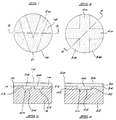
- a tool component comprises an abrasive compact layer 10 bonded to a cemented carbide substrate 12 along an interface 14.
- the abrasive compact layer 10 has an upper flat working surface 16 having a circular periphery 18 which provides a continuous cutting edge for the component.
- a recess 20 extends from the interface 14 into the cemented carbide substrate 12.
- the recess is V-shaped in plan, as can be seen from Figure 1, and has side walls 22 and a flat base 24.
- the intersection of the "V" has a portion 21 which is coincident with the periphery of the carbide substrate 12.
- the recess 20 is filled with the same abrasive compact as that of the layer 10.
- the compact-filled recess 20 has a portion, shown by the dotted lines 26 in Figure 2, which is located in the interface 14. This portion 26 typically has an area at least 25 percent the area of the interface 14.
- a tool component comprises an abrasive compact layer 30 bonded to a cemented carbide substrate 32 along an interface 34.
- the abrasive compact layer 30 has an upper working surface 36 which is flat and which has a circular periphery 38. It is this circular periphery 38 which provides a continuous cutting edge for the component.
- a recess 40 extends into the substrate 32 from the interface 34.
- the recess 40 is cross-shaped, as can be seen from Figure 3, and has side walls 42 and a flat base 44. The intersection of the cross lies wholly within the periphery of the carbide substrate 32.
- the recess 40 has a portion, indicated by dotted lines 46 in Figure 4, located in the interface 34. This portion typically has an area at least 25 percent the area of the interface.
- a cemented carbide substrate or green form thereof may have an appropriately shaped recess formed in one surface thereof and the components necessary to produce an abrasive compact placed on the surface of the substrate which has the recess formed therein.
- This unbonded assembly is then subjected to the elevated temperature and pressure conditions required to produce an abrasive compact of the components.
Landscapes
- Engineering & Computer Science (AREA)
- Mechanical Engineering (AREA)
- Mining & Mineral Resources (AREA)
- Life Sciences & Earth Sciences (AREA)
- Chemical & Material Sciences (AREA)
- Geology (AREA)
- Crystallography & Structural Chemistry (AREA)
- Physics & Mathematics (AREA)
- Manufacturing & Machinery (AREA)
- Environmental & Geological Engineering (AREA)
- Fluid Mechanics (AREA)
- Composite Materials (AREA)
- Materials Engineering (AREA)
- General Life Sciences & Earth Sciences (AREA)
- Geochemistry & Mineralogy (AREA)
- Polishing Bodies And Polishing Tools (AREA)
Description
- This invention relates to tool components comprising a composite abrasive compact.
- Composite abrasive compacts consist of an abrasive compact layer bonded to a substrate which is generally a cemented carbide substrate. The abrasive compact layer comprises a mass of abrasive particles, typically diamond or cubic boron nitride, bonded into a hard conglomerate. Such layers are polycrystalline in nature and contain a high abrasive particle content. Diamond compacts are also known as polycrystalline diamond or PCD. Cubic boron nitride compacts are also known as polycrystalline cubic boron nitride or PCBN.
- Composite abrasive compacts are manufactured under elevated temperature and pressure conditions, e.g. diamond or cubic boron nitride synthesis conditions.
- Composite abrasive compacts are used in a variety of cutting, drilling, milling and other such operations. It is an edge or point formed on the abrasive compact layer of such composite compacts which performs the cutting, drilling, milling or other such operation.
- Composite diamond abrasive compacts are used extensively in drilling. While they generally perform admirably in drilling, the diamond compact layer does tend to spall or break under some of the stressful conditions which can be encountered during drilling.
- United States Patent No. 4,861,350 describes a tool component in the form of a composite abrasive compact wherein the abrasive compact has two zones which are joined by an interlocking, common boundary. The one zone provides the cutting edge or point for the tool component, while the other zone is bonded to a cemented carbide substrate. In one embodiment, the cemented carbide substrate has a central portion extending into the abrasive compact defining a peripheral abrasive compact stepped region surrounding the central portion.
- United States Patent No. 5,007,207 discloses a tool insert comprising an abrasive compact bonded to a cemented carbide support. The cutting edge of the tool is provided by the periphery of the compact. A plurality of circular concentric recesses, each filled with abrasive compact material, extend into the cemented carbide support from the compact/carbide interface. The compact-filled grooves are designed to provide, in use, groove-type cutting regions.
- US-A-4 784 023, upon which the preamble of
claim 1 is based, discloses a cutting element comprising a stud and a composite bonded thereto. In turn, the composite comprises a substrate formed of cemented carbide, and a PCD layer bonded to the carbide substrate. The interface between the PCD layer and the carbide substrate is defined by alternating, non-intersecting ridges of PCD and cemented carbide which preferably extend completely across the composite and are mutually interlocked. - According to the present invention, a tool component comprises an abrasive compact layer bonded to a cemented carbide substrate along an interface; the abrasive compact layer having a working surface, on a side opposite to the interface, which is flat and which presents a cutting edge or point on its periphery;
- a recess extending into the substrate from the interface, and
- a material filling the recess and being bonded to the substrate, the material being different to that of the substrate; characterised in that the recess has a shape, in plan, of at least two strips which intersect.
-
-
- Figures 1 and 2 are plan and sectional side views, respectively, of an embodiment of the invention, and
- Figures 3 and 4 are plan and sectional side views, respectively, of a second embodiment of the invention.
-
- The material-filled recess and its location in the cemented carbide substrate has the effect of introducing a compressive pre-stress in the abrasive compact layer thereby strengthening that layer and reducing the incidence of spalling and breakage during use.
- The material-filled recess has a shape, in plan, of at least two strips which intersect. The intersection of the strips may be located entirely within the periphery of the cemented carbide substrate, or have at least one surface which is common with this periphery. Examples of suitable shapes, in plan, for the recess are V-shape and cross-shape.
- The recess will, of course, have a portion which is located in the interface. The area of that portion will generally be at least 25 percent of the area of the interface. Typically, the area of the portion of the recess in the interface will be less than 95 percent of the area of the interface. Preferably, the area of the portion of the recess in the interface will be 40 to 75 percent of the area of the interface.
- The recess may extend a substantial depth into the substrate. The depth will depend on various factors such as the nature of the material which fills the recess and the shape and configuration of the recess.
- The base of the recess may be flat or have one or more discontinuities which, when provided, are preferably provided by surfaces which define an angle therebetween.
- It is important that the recess be filled with material that is different to the substrate and such as to produce in the compact layer a compressive pre-stress which strengthens that layer. To achieve this, the material will typically be stiffer than the carbide of the substrate, and may also have greater thermal shrinkage and/or thermal expansion properties than the carbide of the substrate.
- In one preferred form of the invention, the material is abrasive compact which is the same as the abrasive compact layer. This preferred aspect of the invention has particular application to tool components wherein the abrasive compact layer is a diamond abrasive compact layer.
- The material filling the recess may also be a cemented carbide having diamond particles dispersed therein, or a cemented carbide having different characteristics to that of the substrate, e.g. a coarser grain size and/or a high metal binder content.
- The cemented carbide for the substrate may be any known in the art such as cemented titanium carbide, cemented tungsten carbide, cemented tantalum carbide, cemented molybdenum carbide, or mixtures thereof. As is known, such cemented carbides will typically have a metal binder content of 3 to 30 percent by mass. The metal binder will typically be cobalt, iron or nickel or an alloy containing one or more of these metals.
- The abrasive compact has a working surface on a side opposite to the interface between the compact layer and the cemented carbide substrate. This surface is flat and presents a cutting edge around, or point in its periphery. Typically, this layer will be circular in plan and the circular periphery will provide a continuous cutting edge.
- The tool components of the invention have particular application in rotary drill bits for drilling earth formations.
- Embodiments of the invention will now be described with reference to the accompanying drawings. Referring first to Figures 1 and 2, a tool component comprises an abrasive
compact layer 10 bonded to a cementedcarbide substrate 12 along aninterface 14. The abrasivecompact layer 10 has an upper flat workingsurface 16 having acircular periphery 18 which provides a continuous cutting edge for the component. - A
recess 20 extends from theinterface 14 into the cementedcarbide substrate 12. The recess is V-shaped in plan, as can be seen from Figure 1, and hasside walls 22 and aflat base 24. The intersection of the "V" has aportion 21 which is coincident with the periphery of thecarbide substrate 12. - The
recess 20 is filled with the same abrasive compact as that of thelayer 10. - The compact-filled
recess 20 has a portion, shown by thedotted lines 26 in Figure 2, which is located in theinterface 14. Thisportion 26 typically has an area at least 25 percent the area of theinterface 14. - A second embodiment of the invention is illustrated by Figures 3 and 4. Referring to these figures, a tool component comprises an abrasive
compact layer 30 bonded to a cementedcarbide substrate 32 along aninterface 34. The abrasivecompact layer 30 has an upper workingsurface 36 which is flat and which has acircular periphery 38. It is thiscircular periphery 38 which provides a continuous cutting edge for the component. - A
recess 40 extends into thesubstrate 32 from theinterface 34. Therecess 40 is cross-shaped, as can be seen from Figure 3, and hasside walls 42 and aflat base 44. The intersection of the cross lies wholly within the periphery of thecarbide substrate 32. - The
recess 40 has a portion, indicated bydotted lines 46 in Figure 4, located in theinterface 34. This portion typically has an area at least 25 percent the area of the interface. - The tool components illustrated above may be made by methods generally known in the art. For example, a cemented carbide substrate or green form thereof, may have an appropriately shaped recess formed in one surface thereof and the components necessary to produce an abrasive compact placed on the surface of the substrate which has the recess formed therein. This unbonded assembly is then subjected to the elevated temperature and pressure conditions required to produce an abrasive compact of the components. These conditions and the apparatus used for carrying out such a method are well known in the art.
Claims (12)
- A tool component comprising an abrasive compact layer (10,30) bonded to a cemented carbide substrate (12, 32) along an interface (14, 34);the abrasive compact layer (10, 30) having a working surface (16, 36), on a side opposite to the interface (14, 34), which is flat and which presents a cutting edge or point on its periphery (18, 38);a recess (20, 40) extending into the substrate (12, 32) from the interface (14, 34), and,a material filling the recess (20, 40) and being bonded to the substrate (12, 32), the material being different to that of the substrate (12, 32);
characterised in that the recess (20, 40) has a shape, in plan, of at least two strips which intersect. - A tool component according to claim 1 wherein the intersection of the strips is located entirely within the periphery of the cemented carbide substrate (32).
- A tool component according to claim 1 wherein the intersection of the strips has at least one surface (21) which is common with the periphery of the cemented carbide substrate (12).
- A tool component according to claim 1 wherein the recess (20), in plan, is V-shaped.
- A tool component according to claim 1 wherein the recess (40), in plan, is cross-shaped.
- A tool component according to any one of the preceding claims wherein the recess (20, 40) has a portion (26, 46) which is located in the interface (14, 34), that portion (26, 46) having an area at least 25 percent the area of the interface (14, 34).
- A tool component according to claim 6 wherein the area of the portion (26, 46) of the recess (20, 40) in the interface (14, 34) is less than 95 percent of the area of the interface (14, 34).
- A tool component according to claim 6 wherein the area of the portion (26, 46) of the recess (20, 40) in the interface (14, 34) is 40 to 75 percent the area of the interface (14, 34).
- A tool component according to any one of the preceding claims wherein the material filling the recess (20, 40) is abrasive compact which is the same as the abrasive compact layer (10, 30).
- A tool component according to any one of claims 1 to 8 wherein the material filling the recess (20, 40) is a cemented carbide having diamond particles dispersed therein.
- A tool component according to any one of claims 1 to 8 wherein the material filling the recess (20, 40) is a cemented carbide having different characteristics to the cemented carbide of the substrate (12, 32).
- A tool component according to any one of the preceding claims wherein the abrasive compact layer (10, 30) is a diamond abrasive compact layer.
Applications Claiming Priority (2)
| Application Number | Priority Date | Filing Date | Title |
|---|---|---|---|
| ZA939571 | 1993-12-21 | ||
| ZA939571 | 1993-12-21 |
Publications (2)
| Publication Number | Publication Date |
|---|---|
| EP0659510A1 EP0659510A1 (en) | 1995-06-28 |
| EP0659510B1 true EP0659510B1 (en) | 1999-04-28 |
Family
ID=25583543
Family Applications (1)
| Application Number | Title | Priority Date | Filing Date |
|---|---|---|---|
| EP94309542A Expired - Lifetime EP0659510B1 (en) | 1993-12-21 | 1994-12-20 | Tool component |
Country Status (4)
| Country | Link |
|---|---|
| US (1) | US5685769A (en) |
| EP (1) | EP0659510B1 (en) |
| DE (1) | DE69418161T2 (en) |
| ZA (1) | ZA9410016B (en) |
Cited By (6)
| Publication number | Priority date | Publication date | Assignee | Title |
|---|---|---|---|---|
| US8936659B2 (en) | 2010-04-14 | 2015-01-20 | Baker Hughes Incorporated | Methods of forming diamond particles having organic compounds attached thereto and compositions thereof |
| US8985248B2 (en) | 2010-08-13 | 2015-03-24 | Baker Hughes Incorporated | Cutting elements including nanoparticles in at least one portion thereof, earth-boring tools including such cutting elements, and related methods |
| US9140072B2 (en) | 2013-02-28 | 2015-09-22 | Baker Hughes Incorporated | Cutting elements including non-planar interfaces, earth-boring tools including such cutting elements, and methods of forming cutting elements |
| US9962669B2 (en) | 2011-09-16 | 2018-05-08 | Baker Hughes Incorporated | Cutting elements and earth-boring tools including a polycrystalline diamond material |
| US10005672B2 (en) | 2010-04-14 | 2018-06-26 | Baker Hughes, A Ge Company, Llc | Method of forming particles comprising carbon and articles therefrom |
| US10066441B2 (en) | 2010-04-14 | 2018-09-04 | Baker Hughes Incorporated | Methods of fabricating polycrystalline diamond, and cutting elements and earth-boring tools comprising polycrystalline diamond |
Families Citing this family (6)
| Publication number | Priority date | Publication date | Assignee | Title |
|---|---|---|---|---|
| AU701094B2 (en) * | 1995-07-03 | 1999-01-21 | De Beers Industrial Diamond Division (Proprietary) Limited | Tool component |
| GB2334269B (en) * | 1998-02-13 | 2002-04-17 | Camco Internat | Improvements in or relating to elements faced with superhard material |
| US6077591A (en) * | 1995-09-23 | 2000-06-20 | Camco International (Uk) Limited | Elements faced with superhard material |
| DE69917958T2 (en) * | 1998-03-09 | 2005-08-25 | Element Six (Pty) Ltd. | abrasives |
| WO2000001918A1 (en) | 1998-07-06 | 2000-01-13 | De Beers Industrial Diamonds (Proprietary) Limited | Abrasive body |
| DE10228503A1 (en) * | 2002-06-21 | 2004-01-15 | MAPAL Fabrik für Präzisionswerkzeuge Dr. Kress KG | Tool for machining valve seats |
Family Cites Families (9)
| Publication number | Priority date | Publication date | Assignee | Title |
|---|---|---|---|---|
| US4109737A (en) * | 1976-06-24 | 1978-08-29 | General Electric Company | Rotary drill bit |
| AU577958B2 (en) * | 1985-08-22 | 1988-10-06 | De Beers Industrial Diamond Division (Proprietary) Limited | Abrasive compact |
| US4784023A (en) * | 1985-12-05 | 1988-11-15 | Diamant Boart-Stratabit (Usa) Inc. | Cutting element having composite formed of cemented carbide substrate and diamond layer and method of making same |
| US4764434A (en) * | 1987-06-26 | 1988-08-16 | Sandvik Aktiebolag | Diamond tools for rock drilling and machining |
| IE61697B1 (en) * | 1987-12-22 | 1994-11-16 | De Beers Ind Diamond | Abrasive product |
| GB8812161D0 (en) * | 1988-05-23 | 1988-06-29 | Fujisawa Pharmaceutical Co | 3-pyrrolidinylthio-1-azabicyclo(3.2.0)hept-2-ene-2-carboxylic acid compounds |
| SE9002137D0 (en) * | 1990-06-15 | 1990-06-15 | Diamant Boart Stratabit Sa | IMPROVED TOOLS FOR CUTTING ROCK DRILLING |
| US5120327A (en) * | 1991-03-05 | 1992-06-09 | Diamant-Boart Stratabit (Usa) Inc. | Cutting composite formed of cemented carbide substrate and diamond layer |
| US5351772A (en) * | 1993-02-10 | 1994-10-04 | Baker Hughes, Incorporated | Polycrystalline diamond cutting element |
-
1994
- 1994-12-15 ZA ZA9410016A patent/ZA9410016B/en unknown
- 1994-12-19 US US08/358,830 patent/US5685769A/en not_active Expired - Fee Related
- 1994-12-20 DE DE69418161T patent/DE69418161T2/en not_active Expired - Fee Related
- 1994-12-20 EP EP94309542A patent/EP0659510B1/en not_active Expired - Lifetime
Cited By (8)
| Publication number | Priority date | Publication date | Assignee | Title |
|---|---|---|---|---|
| US8936659B2 (en) | 2010-04-14 | 2015-01-20 | Baker Hughes Incorporated | Methods of forming diamond particles having organic compounds attached thereto and compositions thereof |
| US9701877B2 (en) | 2010-04-14 | 2017-07-11 | Baker Hughes Incorporated | Compositions of diamond particles having organic compounds attached thereto |
| US10005672B2 (en) | 2010-04-14 | 2018-06-26 | Baker Hughes, A Ge Company, Llc | Method of forming particles comprising carbon and articles therefrom |
| US10066441B2 (en) | 2010-04-14 | 2018-09-04 | Baker Hughes Incorporated | Methods of fabricating polycrystalline diamond, and cutting elements and earth-boring tools comprising polycrystalline diamond |
| US8985248B2 (en) | 2010-08-13 | 2015-03-24 | Baker Hughes Incorporated | Cutting elements including nanoparticles in at least one portion thereof, earth-boring tools including such cutting elements, and related methods |
| US9797201B2 (en) | 2010-08-13 | 2017-10-24 | Baker Hughes Incorporated | Cutting elements including nanoparticles in at least one region thereof, earth-boring tools including such cutting elements, and related methods |
| US9962669B2 (en) | 2011-09-16 | 2018-05-08 | Baker Hughes Incorporated | Cutting elements and earth-boring tools including a polycrystalline diamond material |
| US9140072B2 (en) | 2013-02-28 | 2015-09-22 | Baker Hughes Incorporated | Cutting elements including non-planar interfaces, earth-boring tools including such cutting elements, and methods of forming cutting elements |
Also Published As
| Publication number | Publication date |
|---|---|
| DE69418161T2 (en) | 2000-01-05 |
| ZA9410016B (en) | 1995-08-24 |
| DE69418161D1 (en) | 1999-06-02 |
| US5685769A (en) | 1997-11-11 |
| EP0659510A1 (en) | 1995-06-28 |
Similar Documents
| Publication | Publication Date | Title |
|---|---|---|
| EP0604211B1 (en) | Composite tool for drilling bits | |
| EP0582484B1 (en) | Tool insert | |
| KR100993679B1 (en) | Manufacturing method of tool inserts, tool inserts and polyhedral tool inserts | |
| US5645617A (en) | Composite polycrystalline diamond compact with improved impact and thermal stability | |
| US7070635B2 (en) | Self sharpening polycrystalline diamond compact with high impact resistance | |
| US8016054B2 (en) | Polycrystalline diamond abrasive elements | |
| US5871060A (en) | Attachment geometry for non-planar drill inserts | |
| CA2151899C (en) | Tool component | |
| US5979579A (en) | Polycrystalline diamond cutter with enhanced durability | |
| EP0786300A1 (en) | Composite polycrystalline diamond | |
| US20010037901A1 (en) | Polycrystalline diamond compact cutter having a stress mitigating hoop at the periphery | |
| JPH0348315B2 (en) | ||
| US6149695A (en) | Abrasive body | |
| US5685769A (en) | Tool component | |
| US20180087325A1 (en) | Cutting elements, earth-boring tools including the cutting elements, and methods of forming the earth-boring tools | |
| ZA200509523B (en) | Polycrystalline diamond abrasive elements | |
| ZA200100475B (en) | Abrasive body. | |
| WO2000001916A1 (en) | Abrasive body |
Legal Events
| Date | Code | Title | Description |
|---|---|---|---|
| PUAI | Public reference made under article 153(3) epc to a published international application that has entered the european phase |
Free format text: ORIGINAL CODE: 0009012 |
|
| AK | Designated contracting states |
Kind code of ref document: A1 Designated state(s): BE CH DE FR GB LI SE |
|
| 17P | Request for examination filed |
Effective date: 19950928 |
|
| 17Q | First examination report despatched |
Effective date: 19971110 |
|
| GRAG | Despatch of communication of intention to grant |
Free format text: ORIGINAL CODE: EPIDOS AGRA |
|
| GRAG | Despatch of communication of intention to grant |
Free format text: ORIGINAL CODE: EPIDOS AGRA |
|
| GRAH | Despatch of communication of intention to grant a patent |
Free format text: ORIGINAL CODE: EPIDOS IGRA |
|
| GRAH | Despatch of communication of intention to grant a patent |
Free format text: ORIGINAL CODE: EPIDOS IGRA |
|
| RAP1 | Party data changed (applicant data changed or rights of an application transferred) |
Owner name: DE BEERS INDUSTRIAL DIAMOND DIVISION (PROPRIETARY) |
|
| GRAA | (expected) grant |
Free format text: ORIGINAL CODE: 0009210 |
|
| AK | Designated contracting states |
Kind code of ref document: B1 Designated state(s): BE CH DE FR GB LI SE |
|
| REG | Reference to a national code |
Ref country code: CH Ref legal event code: EP |
|
| REF | Corresponds to: |
Ref document number: 69418161 Country of ref document: DE Date of ref document: 19990602 |
|
| REG | Reference to a national code |
Ref country code: CH Ref legal event code: NV Representative=s name: BOVARD AG PATENTANWAELTE |
|
| ET | Fr: translation filed | ||
| PLBE | No opposition filed within time limit |
Free format text: ORIGINAL CODE: 0009261 |
|
| STAA | Information on the status of an ep patent application or granted ep patent |
Free format text: STATUS: NO OPPOSITION FILED WITHIN TIME LIMIT |
|
| 26N | No opposition filed | ||
| REG | Reference to a national code |
Ref country code: GB Ref legal event code: IF02 |
|
| PGFP | Annual fee paid to national office [announced via postgrant information from national office to epo] |
Ref country code: CH Payment date: 20071213 Year of fee payment: 14 |
|
| PGFP | Annual fee paid to national office [announced via postgrant information from national office to epo] |
Ref country code: SE Payment date: 20071205 Year of fee payment: 14 |
|
| PGFP | Annual fee paid to national office [announced via postgrant information from national office to epo] |
Ref country code: GB Payment date: 20071219 Year of fee payment: 14 Ref country code: FR Payment date: 20071210 Year of fee payment: 14 |
|
| PGFP | Annual fee paid to national office [announced via postgrant information from national office to epo] |
Ref country code: DE Payment date: 20071213 Year of fee payment: 14 |
|
| PGFP | Annual fee paid to national office [announced via postgrant information from national office to epo] |
Ref country code: BE Payment date: 20080314 Year of fee payment: 14 |
|
| BERE | Be: lapsed |
Owner name: *DE BEERS INDUSTRIAL DIAMOND DIVISION (PROPRIETARY Effective date: 20081231 |
|
| REG | Reference to a national code |
Ref country code: CH Ref legal event code: PL |
|
| EUG | Se: european patent has lapsed | ||
| GBPC | Gb: european patent ceased through non-payment of renewal fee |
Effective date: 20081220 |
|
| PG25 | Lapsed in a contracting state [announced via postgrant information from national office to epo] |
Ref country code: BE Free format text: LAPSE BECAUSE OF NON-PAYMENT OF DUE FEES Effective date: 20081231 |
|
| REG | Reference to a national code |
Ref country code: FR Ref legal event code: ST Effective date: 20090831 |
|
| PG25 | Lapsed in a contracting state [announced via postgrant information from national office to epo] |
Ref country code: LI Free format text: LAPSE BECAUSE OF NON-PAYMENT OF DUE FEES Effective date: 20081231 Ref country code: DE Free format text: LAPSE BECAUSE OF NON-PAYMENT OF DUE FEES Effective date: 20090701 Ref country code: CH Free format text: LAPSE BECAUSE OF NON-PAYMENT OF DUE FEES Effective date: 20081231 |
|
| PG25 | Lapsed in a contracting state [announced via postgrant information from national office to epo] |
Ref country code: GB Free format text: LAPSE BECAUSE OF NON-PAYMENT OF DUE FEES Effective date: 20081220 |
|
| PG25 | Lapsed in a contracting state [announced via postgrant information from national office to epo] |
Ref country code: FR Free format text: LAPSE BECAUSE OF NON-PAYMENT OF DUE FEES Effective date: 20081231 |
|
| PG25 | Lapsed in a contracting state [announced via postgrant information from national office to epo] |
Ref country code: SE Free format text: LAPSE BECAUSE OF NON-PAYMENT OF DUE FEES Effective date: 20081221 |