EP0659304B1 - Method and circuit for charging batteries - Google Patents
Method and circuit for charging batteries Download PDFInfo
- Publication number
- EP0659304B1 EP0659304B1 EP93915602A EP93915602A EP0659304B1 EP 0659304 B1 EP0659304 B1 EP 0659304B1 EP 93915602 A EP93915602 A EP 93915602A EP 93915602 A EP93915602 A EP 93915602A EP 0659304 B1 EP0659304 B1 EP 0659304B1
- Authority
- EP
- European Patent Office
- Prior art keywords
- derivative
- charging
- overcharge
- voltage
- point
- Prior art date
- Legal status (The legal status is an assumption and is not a legal conclusion. Google has not performed a legal analysis and makes no representation as to the accuracy of the status listed.)
- Expired - Lifetime
Links
Images


Classifications
-
- H—ELECTRICITY
- H02—GENERATION; CONVERSION OR DISTRIBUTION OF ELECTRIC POWER
- H02J—ELECTRIC POWER NETWORKS; CIRCUIT ARRANGEMENTS OR SYSTEMS FOR SUPPLYING OR DISTRIBUTING ELECTRIC POWER; SYSTEMS FOR STORING ELECTRIC ENERGY
- H02J7/00—Circuit arrangements for charging or discharging batteries or for supplying loads from batteries
- H02J7/90—Regulation of charging or discharging current or voltage
- H02J7/96—Regulation of charging or discharging current or voltage in response to battery voltage
Definitions
- This invention relates to an improved charging device for rechargeable batteries and cells.
- this invention relates to an improved battery charger capable of very rapid and “gentle” charging of batteries without causing overcharge and overcharge-related effects such as battery overheating or shortening of cycle life.
- this invention relates to an improved battery charger which is capable of automatically determining a reference voltage and controlling the charging cycle accordingly to avoid overcharge.
- Control of the charging process is achieved by periodically interrupting the charging current, determining resistance free voltage V o of the battery in fixed intervals after interruptions of current, and comparing the resistance-free voltage with a reference voltage V REF characteristic of the onset of overcharge reactions.
- the charging current is reduced as necessary, so that the resistance-free voltage does not exceed the reference voltage.
- the reference voltage characteristic of the onset of overcharge reactions is determined during a constant current period of charging by determining the resistance free voltage V o of certain characteristic data points.
- the characteristic data points may be located on a charging curve, which relates resistance-free voltage V o to time t. With reference to FIG. 2, the characteristic points are:
- V REF is chosen as a function of either one, or a weighted average of two or more of the above characteristic points.
- V REF may be computed by increasing values for V I(1) by a certain percentage, or by decreasing values for V k or V I(2) by certain percentage.
- the rechargeable batteries and cells relevant to the present invention are of the type using nickel-cadmium (NiCd), nickel-metal hydride (NiMeH), lead-acid and other chemistries. These are used in various applications ranging from small appliances like shavers, cordless power-tools, portable telephones, computers, toys, etc; as well as traction batteries for forklift trucks, golf carts and electric vehicles.
- the overcharge reactions may require higher voltage and can be prevented simply by limiting the charging voltage to a certain value.
- This simple approach is, unfortunately, only partially successful with certain cell types, e.g. lead acid cells, vented NiCd cells, and sealed Li-ion cells.
- Sealed cells capable of recombination of the overcharge reaction products will usually tolerate overcharge at low rates, where the pressures of by-product gases are low and the heat generation is slow enough for the heat to be easily dissipated and lost.
- the need to stop the charging process when the battery becomes full is not too critical if no electrolyte constituent is being lost.
- continuous overcharge even at a low rate often reduces the cyde life of the cells.
- Rapid charging i.e. charging in less than one hour
- the first problem results from the limited rate of charge distribution or equilibration within the electrode plates, so that some parts of the active mass which are electrochemically more accessible become fully charged and driven into the overcharge reaction, while some other parts of the active mass are not yet fully charged.
- the generalized charge acceptance curve in FIG.1 shows that this problem is aggravated by increasing currents. That is, at higher charge rates the overcharge reactions will begin to show at a lower fraction of full charge. In the overcharge region the current efficiency of the charge reactions is declining and most of the coulumbic energy is being wasted on the overcharge reactions.
- the first section A of the voltage curve V o /t represents the initial rapid voltage increase of a deeply discharged cell due to the first production of M ox , followed by voltage profile flattening during the main charge period, where there are sufficient amounts of both M ox and M red forms of the active mass.
- the second part B of the curve starts at the first inflection point I(1) and reflects the voltage increase due to the onset and then gradual increase of the first overcharge reaction.
- Part C starts at the inflection point I(2), where the overcharge reaction begins to dominate.
- the curve is separated at point K, the point of maximum curvature, so that part C can reflect differences between vented cells C v and sealed cells C s .
- the voltage curve at C v finally flattens to a plateau corresponding to the first overcharge reaction.
- the overcharge reaction results in a noticeable increase in temperature starting at the first inflection point and becoming very visible after the second inflection point I(2).
- cell voltage has a negative temperature coefficient (e.g. NiCd batteries)
- a peak P instead of the plateau will result from the rapid temperature increase in this part of the charging curve at C s .
- More sophisticated methods use detection of the second inflection point 1(2) to stop the charging process. This method permits reducing the charging time to 15 minutes. Some overrun of the inflection point is again necessary, and overcharge is not totally avoided.
- One practical way of determining the onset of overcharge reactions is based on measuring resistance-free (open circuit) voltage during short but frequent interruptions of the charging current and comparing it to an external preselected reference voltage typical of the onset of overcharge reaction. When the sensed resistance-free voltage reaches this preset value (compensated for temperature), the current is gradually reduced so that the reference voltage is never exceeded.
- This method which is described in European Patent Application No. 311,460, may be summarized as a method for recharging cells and batteries utilizing a voltage/time derived function, by charging the cells and batteries with a charging current, periodically interrupting the charging current to provide a current-off interval of fixed duration, sampling the resistance-free voltage V o component of a voltage measured during the current-off interval, selecting an overcharge reference voltage V Ref typical of the onset of overcharge reaction and modulating the charging current so that V o does not exceed V Ref until the cells and batteries are sufficiently charged.
- the reference voltage used to control the charging process along the charge/overcharge line in FIG. 1 depends on the number of cells in the battery, on temperature, and to some degree on cell construction. While it is not especially difficult to set the proper V Ref for the number of cells and their temperature, incorporating the effects of individual cell construction to the value of V Ref is more complicated.
- EP-A-0 005 840 discloses a battery charging apparatus in which two inflection points of the battery charging voltage-time curve are observed for determining when to terminate charging. The charging current is periodically interrupted and a voltage measurement is then taken. A converter of the successive approximation type is employed to determine the battery voltage and supplies the results to a microcomputer, which analyses such information for detecting the inflection points.
- the constants for different types of battery are preset on each occasion.
- US-A-4 639 655 discloses a battery charging arrangement in which the battery voltage is measured during charging and in which the measured voltages and empirically determined voltages relating to the particular type of battery are employed for assessing when to terminate charging.
- WO-92/15142 discloses a battery charging arrangement in which the charging process is accompanied by measurement of a selected parameter, such as the voltage across the connection terminals of the battery, to establish the course of this parameter during charging.
- a corresponding reference parameter which has been empirically determined and which is stored in a memory, is selected for comparison with the measured parameter to determine when charging should be terminated.
- a method for recharging cells and batteries utilizing a voltage/time derived function by charging the cells and batteries with a constant initial charging current, periodically interrupting the charging current to provide a current-off interval of fixed duration, sampling the resistance-free voltage V o of the cell or battery being charged, measured at a fixed time during each current-off interval, selecting an overcharge reference voltage V Ref typical of the onset of overcharge reaction and adjusting the charging current periodically so that V o does not exceed V Ref , whereby significant overcharge is avoided, said method being characterised by: a) compiling the values of V o with respect to time t elapsed since the commencement of charging; b) establishing a first derivative curve dV o /dt of V o and detecting first derivative characteristic points thereon, said first derivative characteristic points on said first derivative curve dV o /dt including a first inflection point I(1), located where said first derivative curve dV o /dt
- V Ref determined by this method will automatically reflect the number of cells, temperature and construction, thus permitting the charging device to recharge any subject battery without prior knowledge of its individual parameters.
- apparatus including means for delivering a constant initial charging current to cells and batteries, means for determining a voltage/time derived function of the cells and batteries, means for periodically interrupting the charging current to provide a current-off interval of fixed duration, means for sampling the resistance-free voltage V o of the cell or battery to be charged, measured at a fixed time during each current-off interval, means for selecting an overcharge reference voltage V Ref typical of the onset of overcharge reaction and means for adjusting the charging current periodically so that V o does not exceed V Ref , whereby significant overcharge is avoided, said apparatus being characterised by: a) means for compiling the values of V o with respect to time elapsed since the commencement of charging; b) means for establishing a first derivative curve dV o /dt of V o and detecting first derivative characteristic points thereon, said means for establishing said first derivative characteristic points on said first derivative curve dV o /dt including means for establishing a first inflection
- a preferred embodiment incorporates a microprocessor to coordinate and perform many of the required functions.
- FIG. 1 is a graph showing generalized charge acceptance for rechargeable batteries under rapid charging conditions.
- FIG. 2 is a graph showing generalized temperature and charging curves with respect to elapsed charging time t.
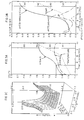
- FIG. 3A is a graph showing temperature and resistance-free voltage V o with respect to time t, measured at 15 msec and 495 msec during the current-off interval, for cell brand X, charged with 5A current at a rate of 8C, with the cell initially at ambient room temperature.
- FIG. 3B is a graph showing the first and second derivate curves of the 15msec V o (t) curve of FIG. 3A.
- FIG. 3C is a three dimensional graph showing V o (t) curves for values of V o measured at various times t o during the current-off intervals, under the conditions of FIG. 3A.
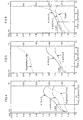
- FIG. 4 is similar to FIG. 3A except that charge current was 2.5A and charge rate is 4C.
- FIG. 5 is similar to FIG. 3A except that the initial cell temperature was about 53°C and charge current was 10A.
- FIG. 6 is similar to FIG. 3A except that cell brand Y was used.
- FIG. 7 is similar to FIG. 4 except that cell brand Y was used and the charge rate was 4C.
- FIG. 8 is similar to FIG. 5 except that cell brand Y was used and the initial cell temperature was about 49°C.
- FIG. 9A is similar to FIG. 3A except that cell brand W was used.
- FIG. 9B is a graph showing the first and second derivative curves of the V o (t) curve of FIG. 9A.
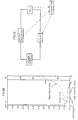
- FIG. 10 is a schematic circuit diagram for one embodiment of the invention.
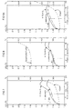
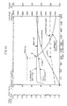
- FIG. 11 is a graph showing results obtained with the charger of the invention with one particular cell type at an ambient temperature.
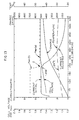
- FIG. 12 is similar to FIG. 11 except that the cell temperature was elevated.
- FIG. 13 is a graph showing the results obtained with the charger of the invention with a second cell type at an ambient temperature.
- FIGS. 3A and 4 show charging data obtained with two sealed NiCd cells of AA size and 600 mAh label capacity produced by battery-maker X, charged with 5 A current (8C rate), and with 2.5 A current (4C rate).
- FIG. 5 shows the same cell X charged at a higher temperature of about 53°C with 10A (8C rate).
- FIGS. 6-8 show parallel charging data obtained with cells of another manufacturer designated Y. Cells X and Y were selected to represent extreme examples in the range of industrial cells.
- FIG. 3C using the conditions used for FIG. 3A, shows a complete individual voltage decay curve (values of V o ) taken over 500 msec long current-off periods which are repeated every 10 sec. During the current-off periods voltage decay curves are sampled at t o every 10 msec, as well as during the preceding and following 100 msec.
- voltage samples taken at 15 and 495 msec after interrupting the current are plotted as two separate resistance free voltage profile curves, together with the temperature profile.
- the temperature profile curve (measured by a thermocouple touching the outside surface of the cell) shows the increase in slope due to overcharge. Due to the external mounting of the thermocouple, the temperature curve is delayed relative to the onset of overcharge reactions.
- FIGS. 5 and 8 were taken with cells X and Y preheated to about 50°C before charging with 10 A current.
- cell X again has a first inflection point on the 15 msec curve at higher voltage than cell Y.
- both hot cells now have inflection point voltages V I(1) 50-100 mV lower, as expected from the temperature coefficient of the NiCd cells. This again corresponds to the experience with these same cell types using known technology described above.
- the resistance-free voltage value at the first inflection point can be used to set the reference voltage V REF for the controlled current part of the charging curve and that it is no longer necessary to know battery voltage, temperature and construction in advance to determine the best value for V REF .
- One method for easily determining the position of the first inflection point I(1) is as a minimum on the first derivative of voltage with respect of time. To eliminate uncertainty caused by small fluctuations of the voltage samples, it is usually necessary to use an electrical or mathematical filter (rolling averages) and to allow certain overrun of the inflection point (a fixed overrun of the minimum on the first derivative curve.)
- V REF V REF in certain relation to the measured value at the inflection point so that the desired driving force of the charging process can be varied as needed.
- One possibility is to set the V REF higher by a fixed percentage than the voltage read at the first inflection point.
- Another possibility is to continue charging until the next characteristic point on the charging curve is detected, which is the point of maximum curvature K.
- This point may be determined by locating the inflection point on the first derivative curve where the second derivative curve d 2 V/dt 2 has a maximum.
- the V REF may then be set equal to the resistance free voltage V K or in certain relation thereto, for example as 98% of the V k value.
- V REF may then be set as a certain percentage less than V I(2) (e.g. at 95% of V I(2) ). This point may be located as the maximum on the first derivative curve dV o /dt.
- V REF is also possible to set the value of V REF as a function of any of these characteristic resistance free voltages V I(1) , V K and V I(2) , for example as a certain weighted average of these values.
- FIG. 3C shows a voltage profile curve generated continuously for varying times during the current off period.
- the function of identifying and confirming the location of the characteristic points on the resistance-free voltage charging curve, reading the characteristic voltages of these points, setting the V REF value based on the measured values of resistance free voltage at these points, and controlling the current to assure that the resistance free voltage V o remains at or below the value of V REF , is most easily achieved using a microprocessor.
- Using a microprocessor also permits adding various safety back-up functions, current control and shut-off criteria. These are important in cases where the inflection point is obscured by the presence of badly mismatched cells in a battery pack, or where there are too many cells in a battery pack (e.g. electric vehide battery). These problems are addressed by using smaller groups of cells within the battery pack and controlling the charging current based on the "weakest link", i.e. the group of cells first realizing the onset of overcharge.
- V K V K as a secondary "failsafe" criterion for setting V REF if the inflection points on the charge curve were obscured because of the shape of the curve.
- FIG. 10 shows a schematic circuit diagram for a preferred embodiment of the claimed invention.
- a rechargeable cell or battery is connected to a power supply along with a shunt resistor for measuring current, a relay to interrupt the current, and a temperature sensor.
- a computerized data acquisition and relay control system e.g. a microprocessor, is used to run and monitor the operation of the circuit.
- a dummy initial reference voltage V REF(i) was set purposely high to allow the initial charging operation to operate at full capacity.
- the microprocessor monitors the values for V o as described above and processes the data to determine the minimum point I(1) on the first derivative curve of V o with respect to time t elapsed since charging commenced, as discussed in general with reference to FIG. 3A.
- an overrun of 0.04 mV/s was allowed before triggering a change of V REF .
- V REF was calculated as 102% of V o at the point of triggering (point Z).
- the microprocessor then set the value for adjusted reference voltage V REF(a) as the value for V o at point I(1), and communicated the value for V REF(a) to a current control system incorporated into the Minit-ChargerTM battery charger.
- V REF(a) As can be seen for both battery brands, in FIGS. 11 - 13, the value for V REF(a) was set at point Z on the graphs.
- the charging circuit of the invention automatically set the V REF(a) according to the nature of each cell, in this case slightly higher for the brand X batteries by about 30mV in tests of similar temperature (FIGS. 11 and 13), which is consistent with known values for these brands.
- the charging circuit of the invention set the V REF(a) about 50mV lower for the hot brand Y cell (FIG. 12), which again is consistent with the known temperature dependence of V REF with NiCd cells.
- V REF(a) Once V REF(a) has been set at point Z, the charging circuit continues to monitor V o as above, and controlling the charging current so that V o never exceeds V REF(a) .
- the adjusted current shows a quick drop and then a tapering off in response to instructions from the microprocessor.
- the cells are rapidly, but gently, charged to saturation without significant overcharge, as shown by the charge curve in FIGS. 11 - 13. Also apparent is the establishment of good temperature control, which is normally a serious problem when charging cells of these types using existing technology.
- the ability of the claimed charging circuit to correctly charge cells of different temperatures without having to be set according to this parameter is a major advance in the art.
- the claimed device will charge a metal hydride or NiCd cell equally well, without having to know the identity or the nature of the different cells.
Landscapes
- Engineering & Computer Science (AREA)
- Power Engineering (AREA)
- Charge And Discharge Circuits For Batteries Or The Like (AREA)
- Secondary Cells (AREA)
Abstract
Description
Claims (6)
- A method for recharging cells and batteries utilizing a voltage/time derived function, by charging the cells and batteries with a constant initial charging current, periodically interrupting the charging current to provide a current-off interval of fixed duration, sampling the resistance-free voltage Vo of the cell or battery being charged, measured at a fixed time during each current-off interval, selecting an overcharge reference voltage VRef typical of the onset of overcharge reaction and adjusting the charging current periodically so that Vo does not exceed VRef whereby significant overcharge is avoided, said method being characterised by:a) compiling the values of Vo with respect to time t elapsed since the commencement of charging;b) establishing a first derivative curve dVo/dt of Vo and detecting first derivative characteristic points thereon, said first derivative characteristic points on said first derivative curve dVo/dt including a first inflection point I(1), located where said first derivative curve dVo/dt has a minimum value, and a second inflection point I(2), located where said first derivative curve dVo/dt has a maximum value;c) establishing a second derivative curve d2Vo/dt2 of Vo and detecting a point of maximum curvature K as a characteristic point on said second derivative curve d2Vo/dt2; andd) selecting the overcharge reference voltage VRef based on the resistance-free voltage value as determined from at least one of said first derivative characteristic points and said second derivative characteristic points.
- The method of claim 1, wherein said overcharge reference voltage VRef is based on the resistance-free voltage value as determined from at least one of said first derivative characteristic points.
- The method of claim 1, wherein said overcharge reference voltage VRef is based on the resistance-free voltage value as determined from any one of said characteristic points, namely, said first inflection point I(1) of said first derivative curve, said second inflection point I(2) of said first derivative curve, and said point of maximum curvature K of said second derivative curve, or any two or all three of said characteristic points.
- A recharging apparatus, the apparatus including means for delivering a constant initial charging current to cells and batteries, means for determining a voltage/time derived function of the cells and batteries, means for periodically interrupting the charging current to provide a current-off interval of fixed duration, means for sampling the resistance-free voltage Vo of the cell or battery to be charged, measured at a fixed time during each current-off interval, means for selecting an overcharge reference voltage VRef typical of the onset of overcharge reaction and means for adjusting the charging current periodically so that Vo does not exceed VRef whereby significant overcharge is avoided, said apparatus being characterised by:a) means for compiling the values of Vo with respect to time elapsed since the commencement of charging;b) means for establishing at least a first derivative curve dVo/dt of Vo and detecting first derivative characteristic points thereon, said means for establishing said first derivative characteristic points on said first derivative curve dVo/dt including means for establishing a first inflection point I(1), located at a point where said first derivative curve dVo/dt has a minimum value, and means for establishing a second inflection point I(2), located at a point where said first derivative curve dVo/dt has a maximum value; andc) means for establishing a second derivative curve d2Vo/dt2 of Vo and detecting a point of maximum curvature K as a characteristic point on said second derivative curve d2Vo/dt2; andd) means for selecting the overcharge reference voltage VRef based on the resistance-free voltage value as determined from at least one of said first derivative characteristic points and said second derivative characteristic point.
- The apparatus of claim 4, including means for selecting said overcharge reference voltage based on the resistance-free voltage value as determined from at least one of said first derivative characteristic points.
- The apparatus of claim 4, including means for selecting said overcharge reference voltage VRef based on the resistance-free voltage value as determined from any one of said characteristic points. namely, said first inflection point I(1) of said first derivative curve, said second inflection point I(2) of said first derivative curve, and said point of maximum curvature K of said second derivative curve, or any two or all three of said characteristic points.
Applications Claiming Priority (3)
| Application Number | Priority Date | Filing Date | Title |
|---|---|---|---|
| US07/943,804 US5477125A (en) | 1992-09-11 | 1992-09-11 | Battery charger |
| US943804 | 1992-09-11 | ||
| PCT/CA1993/000289 WO1994007292A1 (en) | 1992-09-11 | 1993-07-14 | Method and circuit for charging batteries |
Publications (2)
| Publication Number | Publication Date |
|---|---|
| EP0659304A1 EP0659304A1 (en) | 1995-06-28 |
| EP0659304B1 true EP0659304B1 (en) | 1998-04-15 |
Family
ID=25480293
Family Applications (1)
| Application Number | Title | Priority Date | Filing Date |
|---|---|---|---|
| EP93915602A Expired - Lifetime EP0659304B1 (en) | 1992-09-11 | 1993-07-14 | Method and circuit for charging batteries |
Country Status (11)
| Country | Link |
|---|---|
| US (1) | US5477125A (en) |
| EP (1) | EP0659304B1 (en) |
| JP (1) | JP2771331B2 (en) |
| AT (1) | ATE165191T1 (en) |
| AU (1) | AU670447B2 (en) |
| CA (1) | CA2144332C (en) |
| CZ (1) | CZ59495A3 (en) |
| DE (1) | DE69318029T2 (en) |
| PL (1) | PL172473B1 (en) |
| SK (1) | SK31895A3 (en) |
| WO (1) | WO1994007292A1 (en) |
Families Citing this family (27)
| Publication number | Priority date | Publication date | Assignee | Title |
|---|---|---|---|---|
| JPH0785893A (en) * | 1993-09-17 | 1995-03-31 | Sony Corp | Battery charging method |
| US5623195A (en) * | 1994-06-22 | 1997-04-22 | Lucent Technologies Inc. | Apparatus and method for controlling a charging voltage of a battery based on battery temperature |
| US5710506A (en) * | 1995-02-07 | 1998-01-20 | Benchmarq Microelectronics, Inc. | Lead acid charger |
| KR0169392B1 (en) * | 1995-04-24 | 1999-04-15 | 김광호 | Delta voltage detection rapid charging system |
| US5900718A (en) * | 1996-08-16 | 1999-05-04 | Total Battery Management, | Battery charger and method of charging batteries |
| US5729116A (en) * | 1996-12-20 | 1998-03-17 | Total Battery Management, Inc. | Shunt recognition in lithium batteries |
| US5780994A (en) * | 1997-03-21 | 1998-07-14 | Securaplane Technologies, L.L.C. | Detection of inflection point in secondary-battery charging process by matching voltage response to first derivative of battery's characteristic curve |
| US6008624A (en) * | 1997-05-09 | 1999-12-28 | Bergstrom; Gary E. | Method of monitoring and controlling electrochemical systems and processes |
| AUPO917297A0 (en) * | 1997-09-15 | 1997-10-09 | Commonwealth Scientific And Industrial Research Organisation | Charging of batteries |
| US6043631A (en) * | 1998-01-02 | 2000-03-28 | Total Battery Management, Inc. | Battery charger and method of charging rechargeable batteries |
| US6111389A (en) * | 1998-06-18 | 2000-08-29 | Lucent Technologies Inc. | Rapidly charging a battery without overcharging |
| US6867568B1 (en) | 2001-08-13 | 2005-03-15 | John Olson | Battery finish charge device |
| CN1559098A (en) * | 2001-10-03 | 2004-12-29 | ���Ͽع�����˾ | System and method for battery charging |
| US6677730B2 (en) | 2001-12-21 | 2004-01-13 | Energenx, Inc. | Device and method for pulse charging a battery and for driving other devices with a pulse |
| US7589491B2 (en) * | 2006-03-10 | 2009-09-15 | Trojan Battery Company | Temperature compensation in recharging of batteries |
| CA2677883C (en) * | 2006-11-27 | 2014-04-01 | Universal Supercapacitors Llc | Method of charging double electric layer electrochemical capacitors |
| US7990162B2 (en) * | 2007-08-14 | 2011-08-02 | Fluke Corporation | Systems and methods for an open circuit current limiter |
| JP5503318B2 (en) | 2010-02-05 | 2014-05-28 | 古河電気工業株式会社 | Secondary battery charge acceptance limit detection method and apparatus |
| RU2420834C2 (en) * | 2010-05-31 | 2011-06-10 | Алексей Володарович Белицкий | Quick charging method of alkaline sealed accumulators and accumulator batteries, and measurement method of internal temperature of sealed accumulator |
| US10556510B2 (en) | 2012-04-27 | 2020-02-11 | California Institute Of Technology | Accurate assessment of the state of charge of electrochemical cells |
| US9599584B2 (en) * | 2012-04-27 | 2017-03-21 | California Institute Of Technology | Imbedded chip for battery applications |
| JP5283143B1 (en) * | 2012-06-04 | 2013-09-04 | 株式会社西日本エネルギー管理総合研究所 | Operation status diagnosis device, operation status diagnosis method, and operation status diagnosis program for diagnosing operation status for equipment and facilities |
| DE102014206112A1 (en) | 2014-04-01 | 2015-10-01 | Robert Bosch Gmbh | Method for monitoring a state of charge or a charging or discharging current of an accumulator |
| KR102318789B1 (en) * | 2014-09-02 | 2021-10-28 | 삼성전자 주식회사 | Method for managing bettery charging and electlronic device implementing the same |
| CN111033872B (en) * | 2019-04-18 | 2023-05-05 | Oppo广东移动通信有限公司 | Charging method and charging device |
| SE543436C2 (en) | 2019-06-03 | 2021-02-16 | Alelion Energy Systems Ab | Method for estimating state of health of a battery |
| EP4369552A1 (en) * | 2022-11-08 | 2024-05-15 | Goodrich Lighting Systems GmbH & Co. KG | Electric aircraft emergency power supply module, aircraft emergency lighting module, and method of charging a power cell of an electric aircraft emergency power supply module |
Citations (2)
| Publication number | Priority date | Publication date | Assignee | Title |
|---|---|---|---|---|
| WO1989010022A1 (en) * | 1988-04-11 | 1989-10-19 | Battery Technologies Inc. | A method and a taper charger for the resistance free charging of a rechargeable battery |
| WO1992015142A1 (en) * | 1991-02-14 | 1992-09-03 | Chartec Laboratories A/S | A method and an apparatus for charging a rechargeable battery |
Family Cites Families (25)
| Publication number | Priority date | Publication date | Assignee | Title |
|---|---|---|---|---|
| US3517293A (en) * | 1967-01-31 | 1970-06-23 | Mcculloch Corp | Rapid charging of batteries |
| SE358519B (en) * | 1968-05-27 | 1973-07-30 | Macharg J A | |
| US3559025A (en) * | 1968-07-15 | 1971-01-26 | Mcculloch Corp | Rapid charging of batteries |
| US3597673A (en) * | 1969-06-26 | 1971-08-03 | Mcculloch Corp | Rapid charging of batteries |
| BE757705R (en) * | 1969-10-20 | 1971-04-01 | Mcculloch Corp | METHOD AND APPARATUS FOR RAPID CHARGING OF A BATTERY |
| US3614582A (en) * | 1970-07-13 | 1971-10-19 | Mcculloch Corp | Rapid charging of batteries |
| US3761795A (en) * | 1972-01-13 | 1973-09-25 | Legg Ltd | Battery charging apparatus |
| GB1438290A (en) * | 1972-10-14 | 1976-06-03 | ||
| GB1449610A (en) * | 1972-12-29 | 1976-09-15 | Electric Power Storage Ltd | Electric circuits particularly for automatic battery charging apparatus |
| GB1453860A (en) * | 1973-05-17 | 1976-10-27 | Macharg J A | Control systems for battery chargers |
| US3936718A (en) * | 1973-09-24 | 1976-02-03 | Westinghouse Brake & Signal Company Limited | Battery charging control circuits |
| GB1486425A (en) * | 1973-12-21 | 1977-09-21 | Macharg J A | Control systems for battery charges |
| US4016473A (en) * | 1975-11-06 | 1977-04-05 | Utah Research & Development Co., Inc. | DC powered capacitive pulse charge and pulse discharge battery charger |
| CA1153061A (en) * | 1978-05-31 | 1983-08-30 | David A. Saar | Method of charging batteries and apparatus therefor |
| US4388582A (en) * | 1978-05-31 | 1983-06-14 | Black & Decker Inc. | Apparatus and method for charging batteries |
| US4392101A (en) * | 1978-05-31 | 1983-07-05 | Black & Decker Inc. | Method of charging batteries and apparatus therefor |
| US4503378A (en) * | 1983-05-02 | 1985-03-05 | General Motors Corporation | Charging system for nickel-zinc batteries |
| US4639655A (en) * | 1984-04-19 | 1987-01-27 | Westhaver Lawrence A | Method and apparatus for battery charging |
| US4746852A (en) * | 1984-10-29 | 1988-05-24 | Christie Electric Corp. | Controller for battery charger |
| CA1330828C (en) * | 1987-10-09 | 1994-07-19 | Jiri K. Nor | Battery charger |
| EP0444617B1 (en) * | 1990-02-28 | 1996-08-21 | Hitachi Maxell Ltd. | Method of charging secondary batteries |
| US5396163A (en) * | 1991-03-13 | 1995-03-07 | Inco Limited | Battery charger |
| CA2038160C (en) * | 1991-03-13 | 1996-10-22 | Jiri K. Nor | Charging circuits for rechargeable batteries and cells |
| AT406719B (en) * | 1991-06-05 | 2000-08-25 | Enstore Forschungs Entwicklung | METHOD FOR PREFERRED FAST CHARGING OF BATTERIES |
| US5206578A (en) * | 1991-10-15 | 1993-04-27 | Norvik Technologies Inc. | Monitoring system for batteries during charge and discharge |
-
1992
- 1992-09-11 US US07/943,804 patent/US5477125A/en not_active Expired - Lifetime
-
1993
- 1993-07-14 AU AU45551/93A patent/AU670447B2/en not_active Ceased
- 1993-07-14 CZ CZ95594A patent/CZ59495A3/en unknown
- 1993-07-14 SK SK318-95A patent/SK31895A3/en unknown
- 1993-07-14 JP JP6507621A patent/JP2771331B2/en not_active Expired - Lifetime
- 1993-07-14 EP EP93915602A patent/EP0659304B1/en not_active Expired - Lifetime
- 1993-07-14 WO PCT/CA1993/000289 patent/WO1994007292A1/en not_active Ceased
- 1993-07-14 CA CA002144332A patent/CA2144332C/en not_active Expired - Fee Related
- 1993-07-14 PL PL93309289A patent/PL172473B1/en unknown
- 1993-07-14 AT AT93915602T patent/ATE165191T1/en not_active IP Right Cessation
- 1993-07-14 DE DE69318029T patent/DE69318029T2/en not_active Expired - Fee Related
Patent Citations (2)
| Publication number | Priority date | Publication date | Assignee | Title |
|---|---|---|---|---|
| WO1989010022A1 (en) * | 1988-04-11 | 1989-10-19 | Battery Technologies Inc. | A method and a taper charger for the resistance free charging of a rechargeable battery |
| WO1992015142A1 (en) * | 1991-02-14 | 1992-09-03 | Chartec Laboratories A/S | A method and an apparatus for charging a rechargeable battery |
Also Published As
| Publication number | Publication date |
|---|---|
| PL309289A1 (en) | 1995-10-02 |
| WO1994007292A1 (en) | 1994-03-31 |
| JP2771331B2 (en) | 1998-07-02 |
| PL172473B1 (en) | 1997-09-30 |
| AU670447B2 (en) | 1996-07-18 |
| CA2144332C (en) | 1996-12-31 |
| CA2144332A1 (en) | 1994-03-31 |
| CZ59495A3 (en) | 1995-09-13 |
| SK31895A3 (en) | 1995-08-09 |
| US5477125A (en) | 1995-12-19 |
| ATE165191T1 (en) | 1998-05-15 |
| JPH08500238A (en) | 1996-01-09 |
| DE69318029T2 (en) | 1998-11-26 |
| DE69318029D1 (en) | 1998-05-20 |
| EP0659304A1 (en) | 1995-06-28 |
| AU4555193A (en) | 1994-04-12 |
Similar Documents
| Publication | Publication Date | Title |
|---|---|---|
| AU670447B2 (en) | Method and circuit for charging batteries | |
| US5900718A (en) | Battery charger and method of charging batteries | |
| US5864220A (en) | Method and apparatus for controlling the charging of a rechargeable battery to ensure that full charge is achieved without damaging the battery | |
| US5686815A (en) | Method and apparatus for controlling the charging of a rechargeable battery to ensure that full charge is achieved without damaging the battery | |
| US5789903A (en) | Method and apparatus for processing batteries | |
| EP1040547B1 (en) | Method and apparatus for charging a rechargeable battery | |
| US5945811A (en) | Pulse charging method and a charger | |
| US6313605B1 (en) | Battery charger and method of charging nickel based batteries | |
| US5451880A (en) | Battery-charging circuit | |
| PL172578B1 (en) | Method and device for charging batteries PL PL PL PL PL PL PL PL | |
| US20010001533A1 (en) | Method and apparatus for charging a rechargeable battery with monitoring of battery temperature rate of change | |
| IE61854B1 (en) | Method and apparatus for determining battery type and modifying operating characteristics | |
| WO2003107505A2 (en) | Charger for rechargeable batteries | |
| US5617009A (en) | Rechargeable battery charging circuit which sets supplemental charging capacity according to ambient temperature | |
| EP1132989B1 (en) | Device and method for controlled charging of a secondary battery | |
| GB2396755A (en) | Battery charger for several nominal voltages | |
| AU710799B2 (en) | Control and termination of a battery charging process | |
| JP3157687B2 (en) | Storage battery charge control device | |
| JP2906862B2 (en) | Battery charging method | |
| KR19980020456A (en) | Charging end voltage control method according to temperature change in electric vehicle storage | |
| KR100620871B1 (en) | How to charge the charger for small rechargeable batteries | |
| JPH11191936A (en) | Battery charger | |
| AU3511699A (en) | A method and apparatus for processing batteries | |
| JPH08115746A (en) | Method for charging secondary battery | |
| NZ283106A (en) | Discharge of rechargeable battery terminated upon detection of predetermined pattern of rate of change of battery voltage |
Legal Events
| Date | Code | Title | Description |
|---|---|---|---|
| PUAI | Public reference made under article 153(3) epc to a published international application that has entered the european phase |
Free format text: ORIGINAL CODE: 0009012 |
|
| 17P | Request for examination filed |
Effective date: 19950314 |
|
| AK | Designated contracting states |
Kind code of ref document: A1 Designated state(s): AT CH DE FR GB IT LI NL |
|
| RIN1 | Information on inventor provided before grant (corrected) |
Inventor name: CHARLES, DOUGLAS Inventor name: SOLYTS, JOSEPH, V. Inventor name: NOR, JIRI, K. Inventor name: HOHERCAK, JAN Inventor name: ETTEL, VICTOR, ALEXANDER |
|
| 17Q | First examination report despatched |
Effective date: 19950721 |
|
| RAP1 | Party data changed (applicant data changed or rights of an application transferred) |
Owner name: NORVIK TECHNOLOGIES INC. Owner name: INCO LIMITED |
|
| GRAG | Despatch of communication of intention to grant |
Free format text: ORIGINAL CODE: EPIDOS AGRA |
|
| GRAG | Despatch of communication of intention to grant |
Free format text: ORIGINAL CODE: EPIDOS AGRA |
|
| GRAH | Despatch of communication of intention to grant a patent |
Free format text: ORIGINAL CODE: EPIDOS IGRA |
|
| GRAH | Despatch of communication of intention to grant a patent |
Free format text: ORIGINAL CODE: EPIDOS IGRA |
|
| GRAA | (expected) grant |
Free format text: ORIGINAL CODE: 0009210 |
|
| AK | Designated contracting states |
Kind code of ref document: B1 Designated state(s): AT CH DE FR GB IT LI NL |
|
| PG25 | Lapsed in a contracting state [announced via postgrant information from national office to epo] |
Ref country code: AT Free format text: LAPSE BECAUSE OF FAILURE TO SUBMIT A TRANSLATION OF THE DESCRIPTION OR TO PAY THE FEE WITHIN THE PRESCRIBED TIME-LIMIT Effective date: 19980415 |
|
| REF | Corresponds to: |
Ref document number: 165191 Country of ref document: AT Date of ref document: 19980515 Kind code of ref document: T |
|
| REG | Reference to a national code |
Ref country code: CH Ref legal event code: NV Representative=s name: KIRKER & CIE SA Ref country code: CH Ref legal event code: EP |
|
| REF | Corresponds to: |
Ref document number: 69318029 Country of ref document: DE Date of ref document: 19980520 |
|
| ITF | It: translation for a ep patent filed | ||
| PGFP | Annual fee paid to national office [announced via postgrant information from national office to epo] |
Ref country code: FR Payment date: 19980611 Year of fee payment: 6 |
|
| PGFP | Annual fee paid to national office [announced via postgrant information from national office to epo] |
Ref country code: GB Payment date: 19980623 Year of fee payment: 6 |
|
| PGFP | Annual fee paid to national office [announced via postgrant information from national office to epo] |
Ref country code: NL Payment date: 19980629 Year of fee payment: 6 Ref country code: DE Payment date: 19980629 Year of fee payment: 6 |
|
| ET | Fr: translation filed | ||
| PG25 | Lapsed in a contracting state [announced via postgrant information from national office to epo] |
Ref country code: LI Free format text: LAPSE BECAUSE OF NON-PAYMENT OF DUE FEES Effective date: 19980731 Ref country code: CH Free format text: LAPSE BECAUSE OF NON-PAYMENT OF DUE FEES Effective date: 19980731 |
|
| PLBE | No opposition filed within time limit |
Free format text: ORIGINAL CODE: 0009261 |
|
| STAA | Information on the status of an ep patent application or granted ep patent |
Free format text: STATUS: NO OPPOSITION FILED WITHIN TIME LIMIT |
|
| REG | Reference to a national code |
Ref country code: CH Ref legal event code: PL |
|
| 26N | No opposition filed | ||
| PG25 | Lapsed in a contracting state [announced via postgrant information from national office to epo] |
Ref country code: GB Free format text: LAPSE BECAUSE OF NON-PAYMENT OF DUE FEES Effective date: 19990714 |
|
| PG25 | Lapsed in a contracting state [announced via postgrant information from national office to epo] |
Ref country code: FR Free format text: THE PATENT HAS BEEN ANNULLED BY A DECISION OF A NATIONAL AUTHORITY Effective date: 19990731 |
|
| PG25 | Lapsed in a contracting state [announced via postgrant information from national office to epo] |
Ref country code: NL Free format text: LAPSE BECAUSE OF NON-PAYMENT OF DUE FEES Effective date: 20000201 |
|
| GBPC | Gb: european patent ceased through non-payment of renewal fee |
Effective date: 19990714 |
|
| NLV4 | Nl: lapsed or anulled due to non-payment of the annual fee |
Effective date: 20000201 |
|
| PG25 | Lapsed in a contracting state [announced via postgrant information from national office to epo] |
Ref country code: DE Free format text: LAPSE BECAUSE OF NON-PAYMENT OF DUE FEES Effective date: 20000701 |
|
| REG | Reference to a national code |
Ref country code: FR Ref legal event code: ST |
|
| PG25 | Lapsed in a contracting state [announced via postgrant information from national office to epo] |
Ref country code: IT Free format text: LAPSE BECAUSE OF NON-PAYMENT OF DUE FEES Effective date: 20050714 |