EP0659118B1 - Printing method and apparatus - Google Patents
Printing method and apparatus Download PDFInfo
- Publication number
- EP0659118B1 EP0659118B1 EP94910246A EP94910246A EP0659118B1 EP 0659118 B1 EP0659118 B1 EP 0659118B1 EP 94910246 A EP94910246 A EP 94910246A EP 94910246 A EP94910246 A EP 94910246A EP 0659118 B1 EP0659118 B1 EP 0659118B1
- Authority
- EP
- European Patent Office
- Prior art keywords
- receiver
- donor
- dye
- ribbon
- support means
- Prior art date
- Legal status (The legal status is an assumption and is not a legal conclusion. Google has not performed a legal analysis and makes no representation as to the accuracy of the status listed.)
- Expired - Lifetime
Links
Images

Classifications
-
- B—PERFORMING OPERATIONS; TRANSPORTING
- B41—PRINTING; LINING MACHINES; TYPEWRITERS; STAMPS
- B41M—PRINTING, DUPLICATING, MARKING, OR COPYING PROCESSES; COLOUR PRINTING
- B41M5/00—Duplicating or marking methods; Sheet materials for use therein
- B41M5/26—Thermography ; Marking by high energetic means, e.g. laser otherwise than by burning, and characterised by the material used
- B41M5/382—Contact thermal transfer or sublimation processes
- B41M5/38207—Contact thermal transfer or sublimation processes characterised by aspects not provided for in groups B41M5/385 - B41M5/395
- B41M5/38221—Apparatus features
-
- B—PERFORMING OPERATIONS; TRANSPORTING
- B41—PRINTING; LINING MACHINES; TYPEWRITERS; STAMPS
- B41J—TYPEWRITERS; SELECTIVE PRINTING MECHANISMS, i.e. MECHANISMS PRINTING OTHERWISE THAN FROM A FORME; CORRECTION OF TYPOGRAPHICAL ERRORS
- B41J2/00—Typewriters or selective printing mechanisms characterised by the printing or marking process for which they are designed
- B41J2/435—Typewriters or selective printing mechanisms characterised by the printing or marking process for which they are designed characterised by selective application of radiation to a printing material or impression-transfer material
- B41J2/47—Typewriters or selective printing mechanisms characterised by the printing or marking process for which they are designed characterised by selective application of radiation to a printing material or impression-transfer material using the combination of scanning and modulation of light
- B41J2/471—Typewriters or selective printing mechanisms characterised by the printing or marking process for which they are designed characterised by selective application of radiation to a printing material or impression-transfer material using the combination of scanning and modulation of light using dot sequential main scanning by means of a light deflector, e.g. a rotating polygonal mirror
-
- B—PERFORMING OPERATIONS; TRANSPORTING
- B41—PRINTING; LINING MACHINES; TYPEWRITERS; STAMPS
- B41J—TYPEWRITERS; SELECTIVE PRINTING MECHANISMS, i.e. MECHANISMS PRINTING OTHERWISE THAN FROM A FORME; CORRECTION OF TYPOGRAPHICAL ERRORS
- B41J2/00—Typewriters or selective printing mechanisms characterised by the printing or marking process for which they are designed
- B41J2/435—Typewriters or selective printing mechanisms characterised by the printing or marking process for which they are designed characterised by selective application of radiation to a printing material or impression-transfer material
- B41J2/475—Typewriters or selective printing mechanisms characterised by the printing or marking process for which they are designed characterised by selective application of radiation to a printing material or impression-transfer material for heating selectively by radiation or ultrasonic waves
- B41J2/4753—Typewriters or selective printing mechanisms characterised by the printing or marking process for which they are designed characterised by selective application of radiation to a printing material or impression-transfer material for heating selectively by radiation or ultrasonic waves using thermosensitive substrates, e.g. paper
Definitions
- the donor ribbon may be wound on spools, optionally housed in a cartridge or cassette, the spools being movable either side of the support plate in order to place the ribbon into and out of tension about the plate.
- the donor ribbon may be moved out of contact from the receiver, wound on, and retensioned around the curved support plate and back into contact with the fixed receiver.
Landscapes
- Physics & Mathematics (AREA)
- Optics & Photonics (AREA)
- Health & Medical Sciences (AREA)
- General Health & Medical Sciences (AREA)
- Toxicology (AREA)
- Electronic Switches (AREA)
- Thermal Transfer Or Thermal Recording In General (AREA)
Abstract
Description
- The present invention relates to a printing method and apparatus involving the thermal transfer of a dye from a donor to a receiver, including melt, diffusion and sublimation transfer, and especially, but not exclusively, to such a method and apparatus employing a laser as the thermal source. The term "dye" should be taken to cover dyes, inks and pigments.
- In a known type of thermal printer, a dyesheet and receiver sheet are held against one another, with the dyesheet between the receiver sheet and a laser source. The printer receives signals from, for example, video equipment, an electronic still camera or a computer, and controls the laser source accordingly to heat selected individual pixel areas of the dyesheet. This causes dye in the selected areas to transfer to the receiver sheet and form a desired print pattern.
- Commonly, the receiver sheet will comprise a substrate on which is mounted a layer of dye-receptive material, and the dyesheet will comprise a thin substrate supporting a dye donor layer and a laser light absorber layer, with the dye donor layer consisting of a thermally-transferable dye held in a polymeric binder and with the absorber layer comprising carbon black as a broad band absorber, or an absorber which absorbs at the particular wavelength of the laser. As an alternative, a single combined donor and absorber layer may be used.
- Additional coatings may be provided on the dyesheet, such as an adhesive subbing layer between the substrate and dye donor/absorber layers. Other coatings may comprise backing layers, mounted on the opposite side of the substrate from the donor layer, for improving the heat resistance, slip and handling properties of the dyesheet. These backings are particularly useful where the dyesheet is wound in a roll, and may tend to stick to itself.
- It is necessary for these additional coatings and the dyesheet substrate to be transparent to the laser radiation as, otherwise, little or no radiation would pass through to the absorber, insufficient heating would occur, and no dye transfer would take place.
- This restriction on the dyesheet materials can be problematic, as a balance must be struck between the transparency of the materials and their handling and other properties. Therefore, either or both the transparency and handling characteristics of the dyesheet are less than optimum, which means that the energy efficiency and speed of the printer and/or the ease of use of the dyesheet is reduced.
- GB-1284266 discloses a method of printing wherein a dye donor is placed adjacent a receiver, and a beam of radiation in one embodiment may pass through the receiver if it is sufficiently thin before impinging upon the donor.
- EP-0327314 discloses a method for imprinting overwrapped packages to create tamper-evident patterns. A patterned laser beam passes through an overwrap layer and strikes an ink coating on a substrate, thereby evaporating ink from the substrate and depositing the evaporated ink in a registered ink pattern on the ink facing side of the overwrap layer.
- It is one object of the present invention to provide a printing apparatus and method which, amongst other advantages, overcomes the above mentioned problem.
- Viewed from a first aspect, the present invention provides a printing method comprising the thermal transfer of dye from a donor to a receiver, said receiver being mounted on a convex surface of a support means, characterised by the step of:
- heating said donor by directing electromagnetic radiation from an electromagnetic radiation source through said support means and said receiver onto said donor.
- Preferably, electromagnetic radiation is used to heat a radiation absorber in the donor to cause the dye to be thermally transferred, wherein the radiation is passed through the receiver to the absorber.
- As in the prior art, the donor and receiver may be in the form of sheets or ribbons held in close proximity to one another, although they could take any other suitable forms, and the absorber may, amongst other arrangements, take the form of a layer on the donor sheet/ribbon either adjacent to or as part of the dye donor layer.
- The invention reverses the prior art arrangements in which for example a laser beam passes through the donor and, instead, passes the radiation through the receiver. An important advantages of this is to remove the restriction on the donor sheet or ribbon that it have good radiation transmissive properties. The donor sheet or ribbon may therefore be provided with back coatings made of materials able to give optimal handling, slip and heat-resistant properties, etc, and which may be made as thick as desired to increase the donor's toughness and durability.
- A further important, and separate, advantage of the invention is that printing speed in diffusion and sublimation transfer can be increased. Thus, the invention is particularly applicable to diffusion and sublimation transfer. In the known systems, the radiation impinges firstly on the side of the radiation absorber layer which is remote from the receiver. This means that heat is initially dissipated in a region of the donor which is spaced somewhat from the receiver and this slows down the initial rate of transfer of dye from the donor to the receiver. This problem may be more significant where the dye and absorber are combined into a single layer, as the thickness of such a layer may, in some cases, be increased as compared with a separate absorber layer. In accordance with the invention, however, the problem is avoided in that the radiation (having passed through the receiver) initially impinges on the side of the absorber layer which is closest to the receiver, whereby the initial rate of dye transfer and hence the printing speed are increased. This leads to a more efficient system as compared with the prior art configurations.
- The invention requires the receiver to be sufficiently transparent to the radiation to enable the absorber to be heated satisfactorily. It is further preferable for the receiver to be transparent to visible light, so that the printed pattern may be viewed from the opposite side to that on which it was printed. A reason for this is that due to the radiation passing through the receiver, the print pattern resulting from the dye transfer may be the mirror image of that defined by the laser beam or beams when viewed from the side of the receiver onto which the dye is transferred, and so, to compensate for this when the receiver is opaque to visible light, the beam or beams may need to be controlled to heat the donor in a pattern which is the mirror image of that required. If the receiver is transparent to visible light, however, then no reversal need be made, as the pattern may be viewed through the opposite side of the receiver from that on to which the dye is transferred. No reversal is needed either of images for slide projection, as in this case it is the mirror image which is required.
- The invention is especially applicable to printing on slide transparencies (e.g. 35 mm), microfiche, for example used in the archiving of documents, and acetate and polyester films, for example used as overhead projector transparencies.
- The handling properties of the receiver are often of most importance after printing, and the receiver may be mounted on other surfaces, which need not be transparent to the thermal source, to improve these handling properties once the dye transfer is complete. (Indeed the receiver could be mounted on such surfaces before printing, and peeled off prior to or during dye transfer). In contrast, it is the handling properties of the donor prior to and during dye transfer that are important, and these can be improved by the present invention.
- A further problem which may be overcome is that if transparent receivers, such as microfiche, were to be printed upon using the prior art apparatus, then the laser light could pass straight through both the donor and receiver, and pose a health hazard and a danger to eyesight. The present invention, however, allows the donor to be provided with a layer, such as an opaque-radiation absorbing layer, which prevents radiation not absorbed in the dye transfer process from passing through, and removes any health risks, to provide an inherently safer system.
- In a form of the invention, in which an electromagnetic radiation source especially a laser source is used, there may be a deliberate optical misalignment of the system. This reduces any feedback of, for example, a laser beam from any uncoated partially reflective surfaces which may exist on the receiver or a support for it. The misalignment may be achieved by having the various surfaces slightly misaligned to present the laser beam with a series of non-normal surfaces, or by slightly tilting the scanning mirror. In association or as an alternative to misalignment, the beam may be defocussed and/or the surfaces appropriately anti-reflection coated.
- In most thermal transfer printing apparatus the donor and receiver are held closely adjacent one another during exposure to the radiation, and there are a number of known ways of achieving this in which the donor and receiver may take the form of individual sheets or continuous ribbons, and may be stationary or moving. A further advantage of the present invention is that it enables new and advantageous arrangements for supporting the donor and receiver to be employed, which are simple in construction, inexpensive, and easy to use.
- The present invention may advantageously be used in monochrome printing, but may also be used in colour printing, in which, for example, cyan, magenta and yellow, and sometimes black, prints are superimposed over one another to give a colour print. Such colour printing however requires the receiver to be registered accurately in the same position for each cyan, magenta, yellow and black print, and it can be difficult to position a moving receiver ribbon or sheet at its original position prior to each print run, and to move it past a radiation source so that a new print is in accurate registration with those already made. In a colour printing system it is advantageous, therefore, for the receiver to remain stationary throughout each print, and for the radiation source to scan across the receiver surface. This can be readily achieved in accordance with the invention by holding the receiver against a support plate transparent to the thermal source during printing, so that the receiver remains fixed in position on the plate. Different donor sheets may then be substituted, or a donor ribbon of sequential dye strips wound on, to provide a different coloured dye for each successive print as required, without disturbing the receiver, which remains in position and does not need to be re-registered.
- The receiver may also take the form of a sheet or ribbon, and may be mounted on the support plate in a suitable manner, such as by clamping or a vacuum acting on the receiver through apertures in the plate surface. Further, the support plate need not be stationary, but may move across the radiation source during dye transfer. Accurate registration is then still needed, but it is in many cases easier to accurately re-register and control the movement of a solid support plate than a ribbon or sheet.
- Where a receiver sheet is scanned by one or more radiation beams across its width and/or along its length, expensive and cumbersome flat field optics are usually required to correct for the fact that the beam focus scans in an arc, whereas the receiver is flat at the scanning point. To avoid or reduce the need for flat field optics, it is known to provide a concave support which holds the donor and receiver in the curved focal plane of the laser beam in one or more scan directions. This avoids the need for flat field optics completely or only requires correction in one dimension.
- Prior art systems of this sort are not however particularly satisfactory. Generally, donor and receiver sheets are drawn into a concave recess of the support by suction means, with the donor sheet overlying the receiver sheet and facing the radiation source as is required in known arrangements. Such an arrangement is relatively complicated, and does not lend itself readily to donor sheets with different dye colours being used successively over a single receiver sheet, or to winding on a donor sheet to a new dye strip, as the suction means needs to be de-activated and reactivated each time the donor sheet is changed, and the receiver must, in each case, be displaced and then re-registered.
- By the present invention, however, a receiver sheet or ribbon may be mounted on a convex surface of a support plate with a donor sheet or ribbon held thereon. By suitably configuring the convex surface, the receiver and donor sheets/ribbons may be arranged to lie in the focal plane of the laser beam in one or more of its scan directions, so that the radiation may be focused into the plane of the sheets through the plate, and, because the donor is above the receiver, the donor may be easily moved into and out of engagement with the receiver before and after each print run, without needing to move the receiver. This means that no re-registering of the receiver is needed in colour printing. The mounting of the receiver on a convex surface is also advantageous in monochrome printing.
- The donor may be held against the receiver in any suitable manner such as by a vacuum or a pressure pad having a concave surface corresponding to the convex surface of the plate, but in a preferred form, the donor is held in tension around the convex surface and may take the form of a ribbon.
- The donor ribbon may be wound on spools, optionally housed in a cartridge or cassette, the spools being movable either side of the support plate in order to place the ribbon into and out of tension about the plate. To form each colour print, the donor ribbon may be moved out of contact from the receiver, wound on, and retensioned around the curved support plate and back into contact with the fixed receiver.
- The receiver, too, may be a ribbon held under tension around the convex surface of the support plate, or may be mounted to the support plate by adhesive or a vacuum, or in any other suitable manner, such as by being clamped at its edges.
- In a further embodiment, the curved support may be driven to move in a circle or backwards and forwards in an arc, and may, as a result, engage with and disengage from a donor ribbon at the start and end of each print. This may be through friction or a more positive engagement, and on each engagement the donor ribbon may be moved forward by, for example, one colour strip. This may remove the need for a donor ribbon spool drive.
- Where the support is arranged to move, the radiation source may not need to scan in one or more directions.
- A point to note in relation to the present invention and colour printing is that, as the thermal radiation passes through the receiver, it may pass through dye already transferred to the receiver by a prior print run. Preferably, therefore, the dyes themselves are transparent to the thermal radiation, or different colour dyes are transparent to different thermal radiation wavelengths and separate thermal sources having corresponding wavelengths are used to transfer each dye respectively. This helps to prevent a print already formed from being degraded by the thermal radiation, and also reduces back diffusion of the dyes into the dye donor or ribbon. In addition, or as an alternative to this, the thermal source may be activated to compensate for effects of this type during each successive print.
- The radiation may be altered or diverted during its passage through the receiver, and optics may be provided to correct for this prior to the radiation entering the receiver. For example, optics may be provided to correct for bi-refringence, although, in this case, the radiation could be polarised before entering the receiver, or an inherently polarised source such as a laser diode could be used.
- The invention may also extend to apparatus for carrying out any of the above methods. Thus, viewed from a further aspect, the present invention provides thermal transfer printing apparatus comprising means for holding a dye donor and a dye receiver, said dye receiver being mounted in use on a support means having a convex surface, characterised in that:
- an electromagnetic radiation source is arranged, in use, to heat said donor by directing electromagnetic radiation through said support means and said receiver onto said dye donor.
- The dye donor medium is preferably also a sheet or ribbon, and the preferred apparatus comprises a transparent receiver support plate. The apparatus may further comprise means for holding a donor ribbon in tension on the convex side of the plate.
- The preferred thermal radiation source is a laser, such as a laser diode or array of diodes.
- Embodiments of the present invention will now be described, by way of example only, with reference to the accompanying drawings, in which:
- Figure 1 is a schematic front elevation of a dye thermal transfer system according to an embodiment of the present invention;
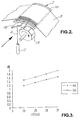
- Figure 2 is a perspective view of a possible scanning arrangement for the system of Fig. 1; and
- Figure 3 shows a graph of laser-on-time against optical density on which are plotted the optical density of prints produced by imaging through (a) a donor and (b) a receiver.
- Figure 1 shows an embodiment of the present invention, in which the
receiver 2, in the form of a sheet, and thedye donor 3, in the form of a ribbon, engage upon acurved support plate 10 concave to the radiation source. - The
receiver 2 is fixed in position on thesupport plate 10 by, for example, an edge clamp, and thedye donor ribbon 3 is held in place through tension. This tension may be applied by moving a pair ofrollers 11 from a position above thesupport plate 10 to a position on either side of it, in which they urge thedonor ribbon 3 downwardly into contact with thesupport plate 10 andreceiver sheet 2, and into tension about them. Thedonor ribbon 3 may, for example, be housed in a cassette or cartridge, and therollers 11 housed in a main printing apparatus body, to be located behind theribbon 3 on insertion of the cassette or cartridge into the body. A modulated laser beam 6 is passed through thesupport plate 10 andreceiver ribbon 2 and may scan across thedye donor ribbon 3 to cause dye transfer. Thesupport plate 10 is curved in such a manner that the laser absorber layer of thedye donor ribbon 3 lies in the scanning plane of the laser beam, and so no flat field lens is required to modify the beam to scan in a flat plane. - A suitable scanning system is shown in Fig. 2, in which a
mirror 12 reflects the beam 6 onto arotating polygon 13 which, in turn, scans the beam along the length of theribbon 3. Thelaser source 7,mirror 12 andpolygon 13 are movably together in the direction of the arrow to allow the beam 6 to scan across the width of the donor ribbon. Alternatively, thesupport plate 10,receiver sheet 2 anddonor ribbon 3 may be moved relative to thepolygon 13 to provide this scanning, or themirror 12 may be rotatable to scan the beam 6. In the latter case, a dynamic focussing assembly would be needed between thelaser source 7 andmirror 12 to compensate for the change in path length of the beam which would otherwise vary the beam's focus. - Instead of this scanning system, an array of laser beams arranged across the width of the
donor ribbon 3 could be scanned together along the ribbon's length, and this could be achieved by using a scanning mirror or rotating polygon or by rotating the laser source array itself. - In this embodiment, the receiver does not move, and so re-registering is not required when producing colour prints. Instead, all that is needed is for the
donor ribbon 3 to disengage from thereceiver sheet 2, and be wound on so that a new colour strip is laid over thereceiver 2 when thedye donor ribbon 3 is re-engaged with thereceiver sheet 2. - In a variation, the
receiver sheet 2 could be in the form of a ribbon held in place by tension about thecurved support plate 10 or by, for example, a vacuum to which the ribbon is subjected by holes to theplate 10. - As a further variant, the laser beam is only scanned across the width of the
donor ribbon 3, or, equivalently, a stationary array of laser beams are provided across the width, and thereceiver 2 andcurved support plate 10 are moved in an arc having a radius of curvature substantially equal to that of the support plate's curved surface. This movement thus effectively provides the scanning along the length of thedye donor ribbon 2, and by continuing the movement to engage and/or disengage thedonor ribbon 3 as thesupport plate 10 moves in a circle or back and forth in an arc, thedonor ribbon 3 may be moved on to the next colour strip after each individual print. This then may remove the need for a donor ribbon spool drive. - By passing the laser beam through the receiver, the beam initially impinges on the side of the absorber layer which is closest to the receiver and so the optical density build up rate is increased as compared with the prior art. This can be seen in the following example:
A magenta dye coat solution was made up as follows:3-methyl-4(3-methyl-4 cyanoisothiazol-5-ylazo)-N-ethyl-N-acetoxyethyl-aniline (Magenta dye) 0.833g Ethyl Cellulose T10 ex. Hercules 0.111g Polyvinylbutyral (BX1) ex. Sekisui 0.444g Hexadeca-b-thionaphthalene Copper (II) phthalocyanine (infra red absorbing dye) 0.197g Tetrahydrofuran 11.1g - This solution was then coated onto 23 µm polyester film with a K4 meyer bar and dried giving a dyecoat with a thickness of 4.5 µm. This donor ribbon was then held against a transparent receiver film comprising a dye receptive coating on transparent 120 µm polyester. Good contact between donor and receiver was maintained by holding them between a platten and nip roller. A 150mW, 817 nm SDL laser diode was collimated and focussed using a 160mm achromat lens, resulting in a laser spot size of 20x30µm at the surface of the media (full width at half power maximum), and a power of 100mW. The laser beam was scanned across the media using a galvanometer scanner, and the laser pulsed for varying lengths of time allowing a series of magenta blocks to be printed in the receiver, the optical density of each block corresponding to the laser on times used. Each individual spot making up the blocks was printed so that its centre lay 20 µm from the spots around it. The transmission optical density of each block was measured using a Sakura densitometer using a green filter. Plots of OD vs laser on time were drawn to compare the rate of OD build up when imaging either through the donor (a) or the receiver (b). These are shown in figure 3.
- Comparison of the curves in fig. 3 shows that printing via irradiation through the receiver improves both the rate of OD build up and the OD maximum attainable.
Claims (12)
- A printing method comprising the thermal transfer of dye from a donor (3) to a receiver (2), said receiver being mounted on a convex surface of a support means (10), characterised by the step of:heating said donor (3) by directing electromagnetic radiation from an electromagnetic radiation source (7), through said support means (10) and said receiver (2) onto said donor (3).
- A printing method according to claim 1, wherein said thermal transfer is by diffusion or sublimation.
- A printing method according to claim 1 or 2, wherein dye is printed to said receiver (2) by successive donors, and wherein said receiver (2) is held stationary on said support means (10) between each print.
- A printing method according to any preceding claim, wherein said support means (10) is moved across said electromagnetic radiation during each print to provide a relative scanning action between said electromagnetic radiation and said receiver (2).
- A printing method according to any preceding claim, wherein said donor (3) is held in tension about said receiver (2) and said support means (10).
- A printing method according to any preceding claim, wherein said receiver (2) is transparent to visible light.
- A printing method according to any preceding claim, wherein said receiver (2) is one of a slide transparency, microfiche, an acetate film, and a polyester film.
- Thermal transfer printing apparatus (1) comprising means for holding a dye donor (3) and a dye receiver (2), said dye receiver (2) being mounted in use on a support means (10) having a convex surface, characterised in that:an electromagnetic radiation source (7) is arranged, in use, to heat said donor (3) by directing electromagnetic radiation through said support means (10) and said receiver (2) onto said dye donor (3).
- Thermal transfer printing apparatus according to claim 8, wherein optical misalignment is provided in said apparatus (1) to prevent feedback of said electromagnetic radiation.
- Thermal transfer printing apparatus according to claim 8 or 9, wherein means are provided for holding said donor (3) in tension about said receiver (2) and said support means (10), in use.
- Thermal transfer printing apparatus according to any of claims 8 to 10, wherein means are provided for placing successive donors adjacent said receiver (2) to effect successive printing to said receiver (2) from said donors, and wherein means are provided for holding said receiver (2) in place on said support means (10) between prints.
- Thermal transfer printing apparatus according to any of claims 8 to 11, wherein said transfer is by diffusion or sublimation.
Applications Claiming Priority (3)
| Application Number | Priority Date | Filing Date | Title |
|---|---|---|---|
| GB9219240 | 1992-09-11 | ||
| GB929219240A GB9219240D0 (en) | 1992-09-11 | 1992-09-11 | Printing method and apparatus |
| PCT/GB1993/001916 WO1994006635A1 (en) | 1992-09-11 | 1993-09-10 | Printing method and apparatus |
Publications (2)
| Publication Number | Publication Date |
|---|---|
| EP0659118A1 EP0659118A1 (en) | 1995-06-28 |
| EP0659118B1 true EP0659118B1 (en) | 1997-12-17 |
Family
ID=10721753
Family Applications (1)
| Application Number | Title | Priority Date | Filing Date |
|---|---|---|---|
| EP94910246A Expired - Lifetime EP0659118B1 (en) | 1992-09-11 | 1993-09-10 | Printing method and apparatus |
Country Status (5)
| Country | Link |
|---|---|
| EP (1) | EP0659118B1 (en) |
| JP (1) | JPH08504134A (en) |
| DE (1) | DE69315850T2 (en) |
| GB (1) | GB9219240D0 (en) |
| WO (1) | WO1994006635A1 (en) |
Families Citing this family (2)
| Publication number | Priority date | Publication date | Assignee | Title |
|---|---|---|---|---|
| EP0605334B1 (en) * | 1992-12-28 | 1997-10-01 | Eastman Kodak Company | Laser-induced thermal dye transfer using reverse exposure |
| US6838155B2 (en) | 2002-02-28 | 2005-01-04 | Woodbridge Foam Corporation | Foam pad and process for production thereof |
Family Cites Families (4)
| Publication number | Priority date | Publication date | Assignee | Title |
|---|---|---|---|---|
| US3408216A (en) * | 1964-12-02 | 1968-10-29 | Xerox Corp | Image reproduction |
| GB1284266A (en) * | 1968-10-16 | 1972-08-02 | Nat Res Dev | Improvements in printing |
| US4865198A (en) * | 1988-02-01 | 1989-09-12 | R. J. Reynolds Tobacco Company | Overwrapped package with tamper indicating means |
| GB8900747D0 (en) * | 1989-01-13 | 1989-03-08 | Payne J M Innovators | Improved printing process |
-
1992
- 1992-09-11 GB GB929219240A patent/GB9219240D0/en active Pending
-
1993
- 1993-09-10 EP EP94910246A patent/EP0659118B1/en not_active Expired - Lifetime
- 1993-09-10 WO PCT/GB1993/001916 patent/WO1994006635A1/en not_active Ceased
- 1993-09-10 JP JP6507889A patent/JPH08504134A/en active Pending
- 1993-09-10 DE DE69315850T patent/DE69315850T2/en not_active Expired - Fee Related
Also Published As
| Publication number | Publication date |
|---|---|
| EP0659118A1 (en) | 1995-06-28 |
| WO1994006635A1 (en) | 1994-03-31 |
| JPH08504134A (en) | 1996-05-07 |
| DE69315850T2 (en) | 1998-04-09 |
| GB9219240D0 (en) | 1992-10-28 |
| DE69315850D1 (en) | 1998-01-29 |
Similar Documents
| Publication | Publication Date | Title |
|---|---|---|
| US4804977A (en) | Image or pattern transfer optical system for thermal dye transfer apparatus | |
| EP0589725B1 (en) | Thermosensitive imaging method and apparatus | |
| US4903042A (en) | Method of and apparatus for making thermocopies | |
| US4928122A (en) | Exposure head | |
| US5183798A (en) | Multiple pass laser printing for improved uniformity of a transferred image | |
| US5711226A (en) | Printing method and apparatus | |
| US5234886A (en) | Thermal dye transfer receiver slide element | |
| EP0529054A1 (en) | FOCUSING A RECORDING LIGHT STRAL WITH THE LIGHT OF DIFFERENT WAVELENGTH. | |
| US5358923A (en) | Color sheet and color transfer method using the same | |
| WO1994006635A1 (en) | Printing method and apparatus | |
| US7206096B1 (en) | Recording method and apparatus | |
| GB2355813A (en) | Process for obtaining a diffusion resistant lenticular element | |
| US5812173A (en) | Thermal transfer printing | |
| US5291217A (en) | Method and apparatus for producing thermal slide transparencies | |
| US5800960A (en) | Uniform background for color transfer | |
| EP0758586A2 (en) | Method and apparatus for dye sublimation transfer printing | |
| EP0583165B1 (en) | Thermal transfer imaging | |
| EP0605334B1 (en) | Laser-induced thermal dye transfer using reverse exposure | |
| JPH0720705B2 (en) | Thermal transfer image forming device | |
| JP3483337B2 (en) | Image forming device | |
| JP2927073B2 (en) | Thermal transfer recording device | |
| US6221806B1 (en) | Diffusion resistant lenticular element | |
| EP0600068B1 (en) | Thermal transfer printing receiver sheet and method | |
| JPH03101974A (en) | Thermal transfer type printer | |
| US5430003A (en) | Thermal transfer printing receiver sheet and method |
Legal Events
| Date | Code | Title | Description |
|---|---|---|---|
| PUAI | Public reference made under article 153(3) epc to a published international application that has entered the european phase |
Free format text: ORIGINAL CODE: 0009012 |
|
| 17P | Request for examination filed |
Effective date: 19950317 |
|
| AK | Designated contracting states |
Kind code of ref document: A1 Designated state(s): BE CH DE FR GB LI |
|
| 17Q | First examination report despatched |
Effective date: 19950814 |
|
| GRAG | Despatch of communication of intention to grant |
Free format text: ORIGINAL CODE: EPIDOS AGRA |
|
| GRAH | Despatch of communication of intention to grant a patent |
Free format text: ORIGINAL CODE: EPIDOS IGRA |
|
| GRAH | Despatch of communication of intention to grant a patent |
Free format text: ORIGINAL CODE: EPIDOS IGRA |
|
| GRAA | (expected) grant |
Free format text: ORIGINAL CODE: 0009210 |
|
| AK | Designated contracting states |
Kind code of ref document: B1 Designated state(s): BE CH DE FR GB LI |
|
| PG25 | Lapsed in a contracting state [announced via postgrant information from national office to epo] |
Ref country code: LI Free format text: LAPSE BECAUSE OF FAILURE TO SUBMIT A TRANSLATION OF THE DESCRIPTION OR TO PAY THE FEE WITHIN THE PRESCRIBED TIME-LIMIT Effective date: 19971217 Ref country code: CH Free format text: LAPSE BECAUSE OF FAILURE TO SUBMIT A TRANSLATION OF THE DESCRIPTION OR TO PAY THE FEE WITHIN THE PRESCRIBED TIME-LIMIT Effective date: 19971217 Ref country code: BE Free format text: LAPSE BECAUSE OF FAILURE TO SUBMIT A TRANSLATION OF THE DESCRIPTION OR TO PAY THE FEE WITHIN THE PRESCRIBED TIME-LIMIT Effective date: 19971217 |
|
| REG | Reference to a national code |
Ref country code: CH Ref legal event code: EP |
|
| REF | Corresponds to: |
Ref document number: 69315850 Country of ref document: DE Date of ref document: 19980129 |
|
| ET | Fr: translation filed | ||
| REG | Reference to a national code |
Ref country code: CH Ref legal event code: PL |
|
| PGFP | Annual fee paid to national office [announced via postgrant information from national office to epo] |
Ref country code: FR Payment date: 19980828 Year of fee payment: 6 |
|
| PGFP | Annual fee paid to national office [announced via postgrant information from national office to epo] |
Ref country code: DE Payment date: 19980930 Year of fee payment: 6 |
|
| PGFP | Annual fee paid to national office [announced via postgrant information from national office to epo] |
Ref country code: GB Payment date: 19981001 Year of fee payment: 6 |
|
| PLBE | No opposition filed within time limit |
Free format text: ORIGINAL CODE: 0009261 |
|
| STAA | Information on the status of an ep patent application or granted ep patent |
Free format text: STATUS: NO OPPOSITION FILED WITHIN TIME LIMIT |
|
| 26N | No opposition filed | ||
| PG25 | Lapsed in a contracting state [announced via postgrant information from national office to epo] |
Ref country code: GB Free format text: LAPSE BECAUSE OF NON-PAYMENT OF DUE FEES Effective date: 19990910 |
|
| GBPC | Gb: european patent ceased through non-payment of renewal fee |
Effective date: 19990910 |
|
| PG25 | Lapsed in a contracting state [announced via postgrant information from national office to epo] |
Ref country code: FR Free format text: LAPSE BECAUSE OF NON-PAYMENT OF DUE FEES Effective date: 20000531 |
|
| PG25 | Lapsed in a contracting state [announced via postgrant information from national office to epo] |
Ref country code: DE Free format text: LAPSE BECAUSE OF NON-PAYMENT OF DUE FEES Effective date: 20000701 |
|
| REG | Reference to a national code |
Ref country code: FR Ref legal event code: ST |