EP0658128B1 - A method and a device for reducing the pressure and the temperature of a steam in a steam conditioning valve - Google Patents
A method and a device for reducing the pressure and the temperature of a steam in a steam conditioning valve Download PDFInfo
- Publication number
- EP0658128B1 EP0658128B1 EP93919755A EP93919755A EP0658128B1 EP 0658128 B1 EP0658128 B1 EP 0658128B1 EP 93919755 A EP93919755 A EP 93919755A EP 93919755 A EP93919755 A EP 93919755A EP 0658128 B1 EP0658128 B1 EP 0658128B1
- Authority
- EP
- European Patent Office
- Prior art keywords
- steam
- valve
- plug
- holes
- jet
- Prior art date
- Legal status (The legal status is an assumption and is not a legal conclusion. Google has not performed a legal analysis and makes no representation as to the accuracy of the status listed.)
- Revoked
Links
Images


Classifications
-
- F—MECHANICAL ENGINEERING; LIGHTING; HEATING; WEAPONS; BLASTING
- F22—STEAM GENERATION
- F22G—SUPERHEATING OF STEAM
- F22G5/00—Controlling superheat temperature
- F22G5/12—Controlling superheat temperature by attemperating the superheated steam, e.g. by injected water sprays
- F22G5/123—Water injection apparatus
- F22G5/126—Water injection apparatus in combination with steam-pressure reducing valves
-
- F—MECHANICAL ENGINEERING; LIGHTING; HEATING; WEAPONS; BLASTING
- F16—ENGINEERING ELEMENTS AND UNITS; GENERAL MEASURES FOR PRODUCING AND MAINTAINING EFFECTIVE FUNCTIONING OF MACHINES OR INSTALLATIONS; THERMAL INSULATION IN GENERAL
- F16K—VALVES; TAPS; COCKS; ACTUATING-FLOATS; DEVICES FOR VENTING OR AERATING
- F16K3/00—Gate valves or sliding valves, i.e. cut-off apparatus with closing members having a sliding movement along the seat for opening and closing
- F16K3/22—Gate valves or sliding valves, i.e. cut-off apparatus with closing members having a sliding movement along the seat for opening and closing with sealing faces shaped as surfaces of solids of revolution
- F16K3/24—Gate valves or sliding valves, i.e. cut-off apparatus with closing members having a sliding movement along the seat for opening and closing with sealing faces shaped as surfaces of solids of revolution with cylindrical valve members
- F16K3/26—Gate valves or sliding valves, i.e. cut-off apparatus with closing members having a sliding movement along the seat for opening and closing with sealing faces shaped as surfaces of solids of revolution with cylindrical valve members with fluid passages in the valve member
- F16K3/267—Combination of a sliding valve and a lift valve
-
- F—MECHANICAL ENGINEERING; LIGHTING; HEATING; WEAPONS; BLASTING
- F16—ENGINEERING ELEMENTS AND UNITS; GENERAL MEASURES FOR PRODUCING AND MAINTAINING EFFECTIVE FUNCTIONING OF MACHINES OR INSTALLATIONS; THERMAL INSULATION IN GENERAL
- F16K—VALVES; TAPS; COCKS; ACTUATING-FLOATS; DEVICES FOR VENTING OR AERATING
- F16K47/00—Means in valves for absorbing fluid energy
- F16K47/04—Means in valves for absorbing fluid energy for decreasing pressure or noise level, the throttle being incorporated in the closure member
-
- F—MECHANICAL ENGINEERING; LIGHTING; HEATING; WEAPONS; BLASTING
- F16—ENGINEERING ELEMENTS AND UNITS; GENERAL MEASURES FOR PRODUCING AND MAINTAINING EFFECTIVE FUNCTIONING OF MACHINES OR INSTALLATIONS; THERMAL INSULATION IN GENERAL
- F16K—VALVES; TAPS; COCKS; ACTUATING-FLOATS; DEVICES FOR VENTING OR AERATING
- F16K47/00—Means in valves for absorbing fluid energy
- F16K47/08—Means in valves for absorbing fluid energy for decreasing pressure or noise level and having a throttling member separate from the closure member, e.g. screens, slots, labyrinths
-
- Y—GENERAL TAGGING OF NEW TECHNOLOGICAL DEVELOPMENTS; GENERAL TAGGING OF CROSS-SECTIONAL TECHNOLOGIES SPANNING OVER SEVERAL SECTIONS OF THE IPC; TECHNICAL SUBJECTS COVERED BY FORMER USPC CROSS-REFERENCE ART COLLECTIONS [XRACs] AND DIGESTS
- Y10—TECHNICAL SUBJECTS COVERED BY FORMER USPC
- Y10S—TECHNICAL SUBJECTS COVERED BY FORMER USPC CROSS-REFERENCE ART COLLECTIONS [XRACs] AND DIGESTS
- Y10S261/00—Gas and liquid contact apparatus
- Y10S261/13—Desuperheaters
Definitions
- the present invention relates to a method and apparatus for reducing the pressure and temperature of steam in a steam conditioning valve, in which steam flow is regulated in a plug perforated by a plurality of holes, a greater or less number of holes being uncovered or closed off in response to the plug movement along a seating formed inside the valve, simultaneously as cooling water is taken into the upper part of the valve such as to be regulated with the aid of a water seat and a plurality of calibrated holes in a hollow valve spindle passing through the plug, and in proportion to regulation of the process steam, this cooling water then being taken through the hollow valve spindle for ejection via a jet downstream in relation to the centre of the departing steam flow.
- steam conditioning is achieved by spraying finely divided water or condensate into the downstream or low pressure side of the valve.
- the coolant is taken into the valve via a so-called water collar in the upper part of the valve, adjacent a yoke for the valve operating means, and subsequently into a hollow valve spindle through a plurality of holes in the upper part thereof, this part regulating the water supply.
- the spindle constitutes an integrated part of the valve plug itself.
- An outside cooling water regulating valve compensates for pressure and temperature variations in the coolant and also for temperature variations in the super-heated steam.
- the coolant or condensate is sprayed in downstream of the valve main seating through the hollow valve spindle and into the centre of the steam flow, where the steam velocity is greatest, pressure low and turbulence very great. These factors contribute to an effective admixture of the coolant to the steam, resulting in rapid vapourisation. Downstream of the valve the steam velocity is reduced once again, and kinetic energy is converted to heat. This further contributes to rapid vapourisation of the coolant.
- the actual steam pressure regulation through the valve is performed with the aid of a plug, which is perforated by a large number of holes having different dimensions, thus achieving an optimum pressure regulation characteristic for the valve.
- the plug is guided by a seating, a greater or less number of these holes being uncovered or closed off to obtain regulation, depending on the position of the plug along the seating.
- a seating a greater or less number of these holes being uncovered or closed off to obtain regulation, depending on the position of the plug along the seating.
- the object of the present invention is thus to provide a method and apparatus of the kind mentioned in the introduction, wherewith the above-mentioned drawbacks are mitigated.
- the distinguishing features of the invention are disclosed in the accompanying claims.
- the steam conditioning valve 1 in accordance with the preferred embodiment, includes a valve housing 2, into which process steam is taken via an inlet 3. Inside the housing 2 there is a valve seating 4, coacting with a plug 5, the lower, sleeve-like part of which is perforated by a plurality of holes 6 for regulating steam flow through the valve 1. Process steam regulation takes place in response to the position of the plug along the seating 4, along which the plug 5 is displaceable, such as to enable a greater or less number of holes to be uncovered.
- a hollow valve spindle 7 extends through the plug 5, the upper part 8 of the spindle 7 having a plurality of calibrating holes 9, which coact with a water seat 10.
- a supply of cooling water to the spindle 7 via an inlet 11 is thus obtained, and will be proportional to the regulation of process steam caused by the movement of the plug 5 along the valve seating 4.
- the spindle 7 forms into a nozzle or jet 12 in the region of its calibrated holes 6, this jet extending downward in the Figs, and past the plug 5 to open out downstream of the centre of the departing steam.
- the spindle 7 is preferably in one piece with the plug 5 and jet 12. The spindle is actuated with the aid of an operating means not illustrated on the drawing.
- the plug 5 In its intermediate region 13 and above the holes 6 the plug 5 is provided with at least one row of holes 14, which, for small opening increments of the valve, give the process steam access to at least one separate duct 15.
- the steam exits from the duct 15 in the vicinity of, and above the coolant outlet openings 16 of the jet 12 such as to flow past and break up the ejected coolant.
- the duct 15 is annular and formed between the curved surface 18 of the jet 12 and a tubular jacket 17 concentric with the jet 12 such as to extend along the curved surface 18 and exit at an annular outlet 19, situated above the outlet/openings 16 of the jet.
- Spacers 20 are arranged between the jet and jacket in the vicinity of the outlet 19 to prevent vibration of the jacket 17.
- the outlet holes 16 of the cooling water jet 12 are at an angle of about 90° to the longitudinal direction of the jet. Accordingly, the process steam flow crosses the cooling water discharge, the steam thus breaking down into very small droplets the jets of water forming the discharge. Since the outward end 21 of the jet 12 is cut off sharply and transversely, water droplets are prevented from adhering to it. This end may also have an increased diameter, thus forming the base of a conical surface starting immediately downstream of the outlet openings 16, which favourably affects the admixture of the coolant into the steam.
- the valve 1 in accordance with the invention, it is provided with a silencer 22, centrally arranged under the plug 5 after the outlet of the main process steam flow for large opening amounts, but before the discharge flow of both coolant and the process steam flowing through the valve for small opening increments, i.e. steam through the annular duct 15.
- the silencer 22 has a plurality of through holes 23 and a large central hole 24 accommodating the lower part of the jet 12.
- the implementation in accordance with the present invention has been found particularly suitable for valve function.
- a plurality of balancing ducts 25 to be formed in the upper part 26 of the plug body, so that they extend axially through the plug 5. There is thus obtained the same pressure both above and below the plug. This permits, inter alia, the use of a smaller operating means for actuating the plug, thus favourably affecting the price of the valve, as well as precision in setting.
- the cap 27 is sealed against the valve housing 2 by an autoclave seal 29, and the spindle 7 is in turn sealed against the cap by a packing gland 30.
Landscapes
- Engineering & Computer Science (AREA)
- General Engineering & Computer Science (AREA)
- Mechanical Engineering (AREA)
- Details Of Valves (AREA)
- Treatment Of Fiber Materials (AREA)
- Control Of Fluid Pressure (AREA)
- Lift Valve (AREA)
Abstract
Description
- The present invention relates to a method and apparatus for reducing the pressure and temperature of steam in a steam conditioning valve, in which steam flow is regulated in a plug perforated by a plurality of holes, a greater or less number of holes being uncovered or closed off in response to the plug movement along a seating formed inside the valve, simultaneously as cooling water is taken into the upper part of the valve such as to be regulated with the aid of a water seat and a plurality of calibrated holes in a hollow valve spindle passing through the plug, and in proportion to regulation of the process steam, this cooling water then being taken through the hollow valve spindle for ejection via a jet downstream in relation to the centre of the departing steam flow.
- In previously known steam conditioning valves of a similar kind at present on the market and known from for example EP-A-0 134 454, steam conditioning is achieved by spraying finely divided water or condensate into the downstream or low pressure side of the valve. The coolant is taken into the valve via a so-called water collar in the upper part of the valve, adjacent a yoke for the valve operating means, and subsequently into a hollow valve spindle through a plurality of holes in the upper part thereof, this part regulating the water supply. The spindle constitutes an integrated part of the valve plug itself. An outside cooling water regulating valve compensates for pressure and temperature variations in the coolant and also for temperature variations in the super-heated steam.
- The coolant or condensate is sprayed in downstream of the valve main seating through the hollow valve spindle and into the centre of the steam flow, where the steam velocity is greatest, pressure low and turbulence very great. These factors contribute to an effective admixture of the coolant to the steam, resulting in rapid vapourisation. Downstream of the valve the steam velocity is reduced once again, and kinetic energy is converted to heat. This further contributes to rapid vapourisation of the coolant. The actual steam pressure regulation through the valve is performed with the aid of a plug, which is perforated by a large number of holes having different dimensions, thus achieving an optimum pressure regulation characteristic for the valve. The plug is guided by a seating, a greater or less number of these holes being uncovered or closed off to obtain regulation, depending on the position of the plug along the seating. However, it has been found with this type of valve that it is difficult to achieve fully satisfactory cooling for small increments of valve openings, i.e. those under 15-20%.
- The object of the present invention is thus to provide a method and apparatus of the kind mentioned in the introduction, wherewith the above-mentioned drawbacks are mitigated. The distinguishing features of the invention are disclosed in the accompanying claims.
- As a result of the invention the above-mentioned problem of leading steam to, and past the cooling water jet for small opening increments of the valve has been solved, hence substantially improving cooling due to the steam breaking up the cooling water jets into very small droplets. This also results in that the water is more easily vapourised, while cooling is made more effective.
- The invention will now be described in more detail with the aid of a preferred embodiment, and with reference to the accompanying drawings, where
- Fig. 1 is a schematic cross-section of a steam conditioning valve in accordance with the present invention,
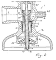
- Fig. 2 is an enlargement of the lower part of the valve in Fig. 1, and
- Fig. 3 is an enlarged depiction of the valve plug illustrated in Fig. 1, and its integration with the valve spindle.
- As will be seen from the drawings, the
steam conditioning valve 1, in accordance with the preferred embodiment, includes avalve housing 2, into which process steam is taken via aninlet 3. Inside thehousing 2 there is avalve seating 4, coacting with aplug 5, the lower, sleeve-like part of which is perforated by a plurality ofholes 6 for regulating steam flow through thevalve 1. Process steam regulation takes place in response to the position of the plug along theseating 4, along which theplug 5 is displaceable, such as to enable a greater or less number of holes to be uncovered. A hollow valve spindle 7 extends through theplug 5, theupper part 8 of the spindle 7 having a plurality of calibratingholes 9, which coact with awater seat 10. A supply of cooling water to the spindle 7 via an inlet 11 is thus obtained, and will be proportional to the regulation of process steam caused by the movement of theplug 5 along thevalve seating 4. Inside theplug 5 the spindle 7 forms into a nozzle orjet 12 in the region of its calibratedholes 6, this jet extending downward in the Figs, and past theplug 5 to open out downstream of the centre of the departing steam. The spindle 7 is preferably in one piece with theplug 5 andjet 12. The spindle is actuated with the aid of an operating means not illustrated on the drawing. - In its
intermediate region 13 and above theholes 6 theplug 5 is provided with at least one row ofholes 14, which, for small opening increments of the valve, give the process steam access to at least oneseparate duct 15. The steam exits from theduct 15 in the vicinity of, and above the coolant outlet openings 16 of thejet 12 such as to flow past and break up the ejected coolant. In the illustrated, preferred embodiment example theduct 15 is annular and formed between thecurved surface 18 of thejet 12 and atubular jacket 17 concentric with thejet 12 such as to extend along thecurved surface 18 and exit at anannular outlet 19, situated above the outlet/openings 16 of the jet.Spacers 20 are arranged between the jet and jacket in the vicinity of theoutlet 19 to prevent vibration of thejacket 17. In the illustrated embodiment there may be in each row between 4 and 8 of theholes 14, which open out into the annular gap forming theduct 15. - As will be seen from the drawings, the
outlet holes 16 of thecooling water jet 12 are at an angle of about 90° to the longitudinal direction of the jet. Accordingly, the process steam flow crosses the cooling water discharge, the steam thus breaking down into very small droplets the jets of water forming the discharge. Since theoutward end 21 of thejet 12 is cut off sharply and transversely, water droplets are prevented from adhering to it. This end may also have an increased diameter, thus forming the base of a conical surface starting immediately downstream of theoutlet openings 16, which favourably affects the admixture of the coolant into the steam. - In the embodiment example illustrated on the drawing of the
valve 1 in accordance with the invention, it is provided with asilencer 22, centrally arranged under theplug 5 after the outlet of the main process steam flow for large opening amounts, but before the discharge flow of both coolant and the process steam flowing through the valve for small opening increments, i.e. steam through theannular duct 15. Thesilencer 22 has a plurality of throughholes 23 and a largecentral hole 24 accommodating the lower part of thejet 12. In the applications where the valve is provided with silencing, the implementation in accordance with the present invention has been found particularly suitable for valve function. - In the majority of applications it is advantageous for a plurality of
balancing ducts 25 to be formed in theupper part 26 of the plug body, so that they extend axially through theplug 5. There is thus obtained the same pressure both above and below the plug. This permits, inter alia, the use of a smaller operating means for actuating the plug, thus favourably affecting the price of the valve, as well as precision in setting. There is a sleeve-like cap 27 inside thevalve housing 2 for guiding theupper part 26 of theplug 5, this cap also being provided withguidance 28 for the valve spindle 7. Thecap 27 is sealed against thevalve housing 2 by anautoclave seal 29, and the spindle 7 is in turn sealed against the cap by apacking gland 30. - The inventive valve functions as will now be described. From the drawings it will be seen that for small valve opening increments, i.e. when all the
holes 6 are covered by the seating 4', see Fig. 3, process steam is fed in through theholes 14 to theannular duct 15. This steam is subsequently taken downwards through theduct 15 to itsoutlet 19, where it practically immediately comes into contact with, and breaks up the cooling water, which, with the aid of thewater seat 10, is fed in proportion to the flow of process steam, this water flowing out through theoutlet openings 16 of thejet 12. By causing the steam to impinge in this way on the jets of cooling water flowing from theoutlet openings 16, a very effective breakdown into droplets is accomplished, as well as easier vapourisation of the cooling water and improvement of steam cooling.
Claims (4)
- Method of reducing the pressure and temperatures of steam in a steam conditioning valve (1), in which steam flow is regulated by a plug (5) perforated by a plurality of first holes (6), such that a greater or less number of holes (6) being uncovered or closed off in response to movement of the plug (5) along a seating (4) formed inside the valve (1), cooling water being simultaneously taken into the upper part (8) of the valve and regulated with the aid of a water seat (10) and a plurality of calibrated second holes (9) in a hollow valve spindle (7) passing through the plug (5), this regulation being proportional to that of the process steam, the cooling water then being taken through the hollow valve spindle (7) for spraying out and through a jet (12) in the centre of the departing steam flow, characterized in that for small opening amounts of the valve (1) process steam is taken directly to the vicinity of the outlet openings (16) of the jet (12) and the cooling water sprayed out therefrom, such as to break up this water by the process steam being caused to impinge on the sprayed-out water simultaneously as partial vapourisation of the water is achieved and process steam cooling is improved.
- Method as claimed in claim 1, characterized in that process steam is taken into an annular space (15) surrounding the jet (12) and is caused to flow from the outlet (19) of this space (15), said outlet being situated immediately above the outlet openings (16) of the cooling water, which is ejected substantially transverse the axial direction of the hollow valve spindle (7), whereby the process steam with its entire unreduced pressure cuts across the direction of the cooling water flow such as to break up the water.
- Apparatus for reducing steam pressure and temperature in a steam conditioning valve (1), including a plug (5) coacting with a seating arranged in a valve housing (2), the plug being perforated by a plurality of first holes (6) for regulating steam flow through the valve (1), a hollow valve spindle (7) passing through the plug and having at its upper portion (8) a plurality of calibrated second holes (9) for coaction with a water seat (10) for feeding cooling water into the hollow spindle (7) in proportion to regulation of the steam, said cooling water flowing through a jet (12) extending downwardly below the plug (5) to exit at the centre of the departing steam flow, characterized in that the plug (5) has in its central region (13) above the first holes (6) at least one row of third holes (14) adapted such that for small amounts of valve openings they lead process steam to at least one separate duct (15) taking the steam to the vicinity of outlet openings (16) for the cooling water in the jet (12).
- Apparatus as claimed in claim 3, characterized in that the separate duct (15) is annular and delimited radially outwardly by a tubular jacket (17) concentric with the jet (12) and extending downwardly along the curved surface (18) of the jet such as to provide an annular outlet (19) above the outlet openings (16).
Applications Claiming Priority (3)
| Application Number | Priority Date | Filing Date | Title |
|---|---|---|---|
| SE9202454A SE501510C2 (en) | 1992-08-26 | 1992-08-26 | Method and apparatus for reducing the pressure and temperature of a steam at a steam conditioning valve |
| SE9202454 | 1992-08-26 | ||
| PCT/SE1993/000683 WO1994004255A1 (en) | 1992-08-26 | 1993-08-17 | A method and a device for reducing the pressure and the temperature of a steam in a steam conditioning valve |
Publications (2)
| Publication Number | Publication Date |
|---|---|
| EP0658128A1 EP0658128A1 (en) | 1995-06-21 |
| EP0658128B1 true EP0658128B1 (en) | 1996-07-31 |
Family
ID=20387014
Family Applications (1)
| Application Number | Title | Priority Date | Filing Date |
|---|---|---|---|
| EP93919755A Revoked EP0658128B1 (en) | 1992-08-26 | 1993-08-17 | A method and a device for reducing the pressure and the temperature of a steam in a steam conditioning valve |
Country Status (7)
| Country | Link |
|---|---|
| US (1) | US5380470A (en) |
| EP (1) | EP0658128B1 (en) |
| JP (1) | JP3201772B2 (en) |
| AT (1) | ATE140876T1 (en) |
| DE (1) | DE69303905T2 (en) |
| SE (1) | SE501510C2 (en) |
| WO (1) | WO1994004255A1 (en) |
Families Citing this family (18)
| Publication number | Priority date | Publication date | Assignee | Title |
|---|---|---|---|---|
| DE4305116A1 (en) * | 1993-02-03 | 1994-08-04 | Holter Gmbh & Co | Injection-cooler for superheated steam |
| SE9502555D0 (en) * | 1995-07-10 | 1995-07-10 | Btg Kaelle Inventing Ab | Device at a pressure control valve |
| US5607626A (en) * | 1995-08-18 | 1997-03-04 | Copes-Vulcan, Inc. | Spring assisted multi-nozzle desuperheater |
| JP3872818B2 (en) * | 1996-08-22 | 2007-01-24 | エスピーエックス コーポレイション | Multi-nozzle overheat reducer with spring assist |
| US6305836B1 (en) * | 1999-07-09 | 2001-10-23 | Apv North America, Inc. | Force absorbing homogenization valve |
| JP2002168407A (en) | 2000-11-30 | 2002-06-14 | Niigata Masoneilan Co Ltd | Steam desuperheating device |
| JP3817132B2 (en) | 2000-11-30 | 2006-08-30 | ニイガタ・メーソンネーラン株式会社 | Steam conversion valve |
| JP3718631B2 (en) * | 2000-11-30 | 2005-11-24 | ニイガタ・メーソンネーラン株式会社 | Steam conversion valve |
| CN1327158C (en) * | 2005-08-03 | 2007-07-18 | 南京汉唐机电设计研究有限公司 | Desuperheating and decompressing device for steam |
| EP1918532B1 (en) * | 2006-10-30 | 2016-04-20 | Valvitalia S.p.A. | Desuperheater apparatus for steam lines |
| US8677585B2 (en) * | 2010-08-20 | 2014-03-25 | Dresser, Inc. | Alignment mechanism for assembly of a diffuser inside a pressure reducing and conditioning valve |
| US9247672B2 (en) * | 2013-01-21 | 2016-01-26 | Parker-Hannifin Corporation | Passively controlled smart microjet cooling array |
| US9612009B2 (en) * | 2013-11-08 | 2017-04-04 | Fisher Controls International Llc | Desuperheater and spray nozzles therefor |
| CN105698006B (en) * | 2016-03-25 | 2018-06-22 | 吴忠仪表有限责任公司 | Integral type reducing-and-cooling plant |
| CN106246930A (en) * | 2016-08-31 | 2016-12-21 | 浙江安耐杰科技股份有限公司 | Steam energy-saving device and method of work thereof |
| CN107191612B (en) * | 2017-05-15 | 2019-01-11 | 环球阀门集团有限公司 | Steam converter valve |
| SE1930345A1 (en) | 2019-10-24 | 2021-04-25 | Bvt Sweden Ab | A Steam Conditioning Valve |
| CN114060528B (en) * | 2022-01-17 | 2022-04-15 | 艾肯(江苏)工业技术有限公司 | Be used for steam system atomizing integral type pressure relief device that reduces temperature |
Family Cites Families (12)
| Publication number | Priority date | Publication date | Assignee | Title |
|---|---|---|---|---|
| US1256853A (en) * | 1916-07-19 | 1918-02-19 | Walter J Warner | Water-heater. |
| US2254472A (en) * | 1939-04-28 | 1941-09-02 | Mason Neilan Regulator Company | Combination control and quench valve |
| US2355458A (en) * | 1941-09-06 | 1944-08-08 | Swartwout Co | Desuperheating valve |
| US3134827A (en) * | 1959-12-23 | 1964-05-26 | Siemens Ag | Steam conversion valve |
| US3732851A (en) * | 1971-05-26 | 1973-05-15 | R Self | Method of and device for conditioning steam |
| US4011287A (en) * | 1975-07-11 | 1977-03-08 | David John Marley | Steam conditioning valve |
| US4071586A (en) * | 1976-10-26 | 1978-01-31 | Copes-Vulcan, Inc. | Variable orifice desuperheater |
| DE3304523C2 (en) * | 1983-02-10 | 1987-01-08 | Holter Regelarmaturen Gmbh & Co Kg, 4815 Schloss Holte-Stukenbrock | Steam conversion valve |
| DE3323990C2 (en) * | 1983-07-02 | 1986-09-04 | Welland & Tuxhorn, 4800 Bielefeld | Multi-stage, regulated throttle device |
| US4718456A (en) * | 1984-04-16 | 1988-01-12 | Steam Systems And Services, Incorporated | Steam conditioning valve |
| US5005605A (en) * | 1989-07-10 | 1991-04-09 | Keystone International Holdings Corp. | Conditioning valve |
| US5012841A (en) * | 1989-08-24 | 1991-05-07 | Keystone International Holdings Corp. | Pressure reducing and conditioning valves |
-
1992
- 1992-08-26 SE SE9202454A patent/SE501510C2/en unknown
-
1993
- 1993-08-17 AT AT93919755T patent/ATE140876T1/en not_active IP Right Cessation
- 1993-08-17 JP JP50616494A patent/JP3201772B2/en not_active Expired - Lifetime
- 1993-08-17 US US08/167,810 patent/US5380470A/en not_active Expired - Lifetime
- 1993-08-17 DE DE69303905T patent/DE69303905T2/en not_active Revoked
- 1993-08-17 WO PCT/SE1993/000683 patent/WO1994004255A1/en not_active Ceased
- 1993-08-17 EP EP93919755A patent/EP0658128B1/en not_active Revoked
Also Published As
| Publication number | Publication date |
|---|---|
| WO1994004255A1 (en) | 1994-03-03 |
| JP3201772B2 (en) | 2001-08-27 |
| US5380470A (en) | 1995-01-10 |
| DE69303905T2 (en) | 1997-02-06 |
| DE69303905D1 (en) | 1996-09-05 |
| ATE140876T1 (en) | 1996-08-15 |
| SE9202454L (en) | 1994-02-27 |
| EP0658128A1 (en) | 1995-06-21 |
| JPH08500428A (en) | 1996-01-16 |
| SE501510C2 (en) | 1995-03-06 |
| SE9202454D0 (en) | 1992-08-26 |
Similar Documents
| Publication | Publication Date | Title |
|---|---|---|
| US5380470A (en) | Method and apparatus for reducing the pressure and temperature of steam in a steam conditioning valve | |
| US5274995A (en) | Apparatus and method for atomizing water in a combustor dome assembly | |
| EP0489018B1 (en) | Pressure reducing and conditioning valves | |
| CA2332096C (en) | Air atomizing nozzle assembly with improved air cap | |
| EP0700497B1 (en) | Improved steam desuperheater | |
| CA2017896C (en) | Conditioning valve | |
| GB2134244A (en) | Pressure atomizing fuel injection assembly | |
| KR870009116A (en) | Gas turbine combustor | |
| GB1559779A (en) | Combustion assembly | |
| US3904722A (en) | Steam reforming device | |
| US3207492A (en) | Apparatus for controlling the pressure and temperature of gas by spraying it with water | |
| US4718456A (en) | Steam conditioning valve | |
| CN109417845A (en) | System and method for the plasma air-flow in stabilized plasma arc torch | |
| US4278619A (en) | Steam throttle valve | |
| US3952416A (en) | Dental handpiece | |
| FI96174B (en) | The spray head | |
| US3245622A (en) | Steam-water spray nozzle | |
| EP0101109B1 (en) | Mix atomizer | |
| CA2335349C (en) | Fuel injector for gas turbine engine | |
| US4404929A (en) | Liquid distributor head actuated by fluid pressure | |
| GB2113303A (en) | I.C. Engine fuel injection nozzle | |
| US4300719A (en) | Steam traps | |
| US5279326A (en) | Safety valve | |
| CN213349337U (en) | Atomizing nozzle | |
| CN113457869A (en) | Spray head protection device of steam injection equipment |
Legal Events
| Date | Code | Title | Description |
|---|---|---|---|
| PUAI | Public reference made under article 153(3) epc to a published international application that has entered the european phase |
Free format text: ORIGINAL CODE: 0009012 |
|
| 17P | Request for examination filed |
Effective date: 19950118 |
|
| AK | Designated contracting states |
Kind code of ref document: A1 Designated state(s): AT DE FR GB IT |
|
| 17Q | First examination report despatched |
Effective date: 19951017 |
|
| GRAH | Despatch of communication of intention to grant a patent |
Free format text: ORIGINAL CODE: EPIDOS IGRA |
|
| GRAH | Despatch of communication of intention to grant a patent |
Free format text: ORIGINAL CODE: EPIDOS IGRA |
|
| GRAA | (expected) grant |
Free format text: ORIGINAL CODE: 0009210 |
|
| AK | Designated contracting states |
Kind code of ref document: B1 Designated state(s): AT DE FR GB IT |
|
| REF | Corresponds to: |
Ref document number: 140876 Country of ref document: AT Date of ref document: 19960815 Kind code of ref document: T |
|
| REF | Corresponds to: |
Ref document number: 69303905 Country of ref document: DE Date of ref document: 19960905 |
|
| ITF | It: translation for a ep patent filed | ||
| ET | Fr: translation filed | ||
| PLBI | Opposition filed |
Free format text: ORIGINAL CODE: 0009260 |
|
| PLBQ | Unpublished change to opponent data |
Free format text: ORIGINAL CODE: EPIDOS OPPO |
|
| PLBF | Reply of patent proprietor to notice(s) of opposition |
Free format text: ORIGINAL CODE: EPIDOS OBSO |
|
| 26 | Opposition filed |
Opponent name: FIRMA WELLAND & TUXHORN ARMATUREN- UND MASCHINENFA Effective date: 19970430 |
|
| PLBF | Reply of patent proprietor to notice(s) of opposition |
Free format text: ORIGINAL CODE: EPIDOS OBSO |
|
| RDAH | Patent revoked |
Free format text: ORIGINAL CODE: EPIDOS REVO |
|
| APAC | Appeal dossier modified |
Free format text: ORIGINAL CODE: EPIDOS NOAPO |
|
| APAC | Appeal dossier modified |
Free format text: ORIGINAL CODE: EPIDOS NOAPO |
|
| APAE | Appeal reference modified |
Free format text: ORIGINAL CODE: EPIDOS REFNO |
|
| REG | Reference to a national code |
Ref country code: GB Ref legal event code: IF02 |
|
| APCC | Communication from the board of appeal sent |
Free format text: ORIGINAL CODE: EPIDOS OBAPO |
|
| APCC | Communication from the board of appeal sent |
Free format text: ORIGINAL CODE: EPIDOS OBAPO |
|
| APBI | Information on receipt of observation in appeal deleted |
Free format text: ORIGINAL CODE: EPIDOSDOBA4O |
|
| APBY | Invitation to file observations in appeal sent |
Free format text: ORIGINAL CODE: EPIDOSNOBA2O |
|
| PGFP | Annual fee paid to national office [announced via postgrant information from national office to epo] |
Ref country code: FR Payment date: 20030731 Year of fee payment: 11 |
|
| PGFP | Annual fee paid to national office [announced via postgrant information from national office to epo] |
Ref country code: GB Payment date: 20030812 Year of fee payment: 11 |
|
| PGFP | Annual fee paid to national office [announced via postgrant information from national office to epo] |
Ref country code: AT Payment date: 20030819 Year of fee payment: 11 |
|
| PGFP | Annual fee paid to national office [announced via postgrant information from national office to epo] |
Ref country code: DE Payment date: 20030826 Year of fee payment: 11 |
|
| APBU | Appeal procedure closed |
Free format text: ORIGINAL CODE: EPIDOSNNOA9O |
|
| RDAG | Patent revoked |
Free format text: ORIGINAL CODE: 0009271 |
|
| STAA | Information on the status of an ep patent application or granted ep patent |
Free format text: STATUS: PATENT REVOKED |
|
| 27W | Patent revoked |
Effective date: 20031123 |
|
| GBPR | Gb: patent revoked under art. 102 of the ep convention designating the uk as contracting state |
Free format text: 20031123 |
|
| APAH | Appeal reference modified |
Free format text: ORIGINAL CODE: EPIDOSCREFNO |