EP0657203B1 - Nitrogen oxides and sulfur oxides removal utilizing transport line absorber - Google Patents
Nitrogen oxides and sulfur oxides removal utilizing transport line absorber Download PDFInfo
- Publication number
- EP0657203B1 EP0657203B1 EP94118446A EP94118446A EP0657203B1 EP 0657203 B1 EP0657203 B1 EP 0657203B1 EP 94118446 A EP94118446 A EP 94118446A EP 94118446 A EP94118446 A EP 94118446A EP 0657203 B1 EP0657203 B1 EP 0657203B1
- Authority
- EP
- European Patent Office
- Prior art keywords
- sorbent particles
- oxides
- gas
- flue gas
- adsorber
- Prior art date
- Legal status (The legal status is an assumption and is not a legal conclusion. Google has not performed a legal analysis and makes no representation as to the accuracy of the status listed.)
- Expired - Lifetime
Links
- MWUXSHHQAYIFBG-UHFFFAOYSA-N nitrogen oxide Inorganic materials O=[N] MWUXSHHQAYIFBG-UHFFFAOYSA-N 0.000 title claims description 126
- 229910052815 sulfur oxide Inorganic materials 0.000 title claims description 42
- XTQHKBHJIVJGKJ-UHFFFAOYSA-N sulfur monoxide Chemical class S=O XTQHKBHJIVJGKJ-UHFFFAOYSA-N 0.000 title claims description 38
- 239000006096 absorbing agent Substances 0.000 title 1
- 239000002245 particle Substances 0.000 claims description 204
- 239000002594 sorbent Substances 0.000 claims description 190
- UGFAIRIUMAVXCW-UHFFFAOYSA-N Carbon monoxide Chemical compound [O+]#[C-] UGFAIRIUMAVXCW-UHFFFAOYSA-N 0.000 claims description 68
- 239000003546 flue gas Substances 0.000 claims description 68
- JTJMJGYZQZDUJJ-UHFFFAOYSA-N phencyclidine Chemical class C1CCCCN1C1(C=2C=CC=CC=2)CCCCC1 JTJMJGYZQZDUJJ-UHFFFAOYSA-N 0.000 claims description 51
- 239000007789 gas Substances 0.000 claims description 39
- 239000007787 solid Substances 0.000 claims description 28
- 238000000034 method Methods 0.000 claims description 16
- 230000005484 gravity Effects 0.000 claims description 13
- 239000012492 regenerant Substances 0.000 claims description 7
- 239000000725 suspension Substances 0.000 claims description 6
- 239000000112 cooling gas Substances 0.000 claims description 4
- 238000001179 sorption measurement Methods 0.000 claims description 4
- TXKMVPPZCYKFAC-UHFFFAOYSA-N disulfur monoxide Inorganic materials O=S=S TXKMVPPZCYKFAC-UHFFFAOYSA-N 0.000 claims description 2
- 239000003570 air Substances 0.000 description 57
- 238000001816 cooling Methods 0.000 description 24
- 238000004064 recycling Methods 0.000 description 7
- 229920006395 saturated elastomer Polymers 0.000 description 7
- NINIDFKCEFEMDL-UHFFFAOYSA-N Sulfur Chemical compound [S] NINIDFKCEFEMDL-UHFFFAOYSA-N 0.000 description 5
- 229910052717 sulfur Inorganic materials 0.000 description 5
- 239000011593 sulfur Substances 0.000 description 5
- 239000011324 bead Substances 0.000 description 4
- 239000010881 fly ash Substances 0.000 description 3
- 238000000926 separation method Methods 0.000 description 3
- PNEYBMLMFCGWSK-UHFFFAOYSA-N Alumina Chemical compound [O-2].[O-2].[O-2].[Al+3].[Al+3] PNEYBMLMFCGWSK-UHFFFAOYSA-N 0.000 description 2
- 238000010438 heat treatment Methods 0.000 description 2
- 230000008929 regeneration Effects 0.000 description 2
- 238000011069 regeneration method Methods 0.000 description 2
- 239000007921 spray Substances 0.000 description 2
- DGAQECJNVWCQMB-PUAWFVPOSA-M Ilexoside XXIX Chemical compound C[C@@H]1CC[C@@]2(CC[C@@]3(C(=CC[C@H]4[C@]3(CC[C@@H]5[C@@]4(CC[C@@H](C5(C)C)OS(=O)(=O)[O-])C)C)[C@@H]2[C@]1(C)O)C)C(=O)O[C@H]6[C@@H]([C@H]([C@@H]([C@H](O6)CO)O)O)O.[Na+] DGAQECJNVWCQMB-PUAWFVPOSA-M 0.000 description 1
- 239000012080 ambient air Substances 0.000 description 1
- 230000015572 biosynthetic process Effects 0.000 description 1
- 239000003245 coal Substances 0.000 description 1
- 239000000567 combustion gas Substances 0.000 description 1
- 230000000052 comparative effect Effects 0.000 description 1
- -1 flue gas 108 Chemical compound 0.000 description 1
- 239000012530 fluid Substances 0.000 description 1
- 230000001172 regenerating effect Effects 0.000 description 1
- 239000011734 sodium Substances 0.000 description 1
- 229910052708 sodium Inorganic materials 0.000 description 1
- 239000000758 substrate Substances 0.000 description 1
- XLYOFNOQVPJJNP-UHFFFAOYSA-N water Substances O XLYOFNOQVPJJNP-UHFFFAOYSA-N 0.000 description 1
Images


Classifications
-
- B—PERFORMING OPERATIONS; TRANSPORTING
- B01—PHYSICAL OR CHEMICAL PROCESSES OR APPARATUS IN GENERAL
- B01D—SEPARATION
- B01D53/00—Separation of gases or vapours; Recovering vapours of volatile solvents from gases; Chemical or biological purification of waste gases, e.g. engine exhaust gases, smoke, fumes, flue gases, aerosols
- B01D53/02—Separation of gases or vapours; Recovering vapours of volatile solvents from gases; Chemical or biological purification of waste gases, e.g. engine exhaust gases, smoke, fumes, flue gases, aerosols by adsorption, e.g. preparative gas chromatography
- B01D53/06—Separation of gases or vapours; Recovering vapours of volatile solvents from gases; Chemical or biological purification of waste gases, e.g. engine exhaust gases, smoke, fumes, flue gases, aerosols by adsorption, e.g. preparative gas chromatography with moving adsorbents, e.g. rotating beds
- B01D53/08—Separation of gases or vapours; Recovering vapours of volatile solvents from gases; Chemical or biological purification of waste gases, e.g. engine exhaust gases, smoke, fumes, flue gases, aerosols by adsorption, e.g. preparative gas chromatography with moving adsorbents, e.g. rotating beds according to the "moving bed" method
-
- B—PERFORMING OPERATIONS; TRANSPORTING
- B01—PHYSICAL OR CHEMICAL PROCESSES OR APPARATUS IN GENERAL
- B01D—SEPARATION
- B01D2253/00—Adsorbents used in seperation treatment of gases and vapours
- B01D2253/10—Inorganic adsorbents
- B01D2253/104—Alumina
-
- B—PERFORMING OPERATIONS; TRANSPORTING
- B01—PHYSICAL OR CHEMICAL PROCESSES OR APPARATUS IN GENERAL
- B01D—SEPARATION
- B01D2253/00—Adsorbents used in seperation treatment of gases and vapours
- B01D2253/25—Coated, impregnated or composite adsorbents
-
- B—PERFORMING OPERATIONS; TRANSPORTING
- B01—PHYSICAL OR CHEMICAL PROCESSES OR APPARATUS IN GENERAL
- B01D—SEPARATION
- B01D2253/00—Adsorbents used in seperation treatment of gases and vapours
- B01D2253/30—Physical properties of adsorbents
- B01D2253/302—Dimensions
- B01D2253/304—Linear dimensions, e.g. particle shape, diameter
-
- B—PERFORMING OPERATIONS; TRANSPORTING
- B01—PHYSICAL OR CHEMICAL PROCESSES OR APPARATUS IN GENERAL
- B01D—SEPARATION
- B01D2257/00—Components to be removed
- B01D2257/30—Sulfur compounds
- B01D2257/302—Sulfur oxides
-
- B—PERFORMING OPERATIONS; TRANSPORTING
- B01—PHYSICAL OR CHEMICAL PROCESSES OR APPARATUS IN GENERAL
- B01D—SEPARATION
- B01D2257/00—Components to be removed
- B01D2257/40—Nitrogen compounds
- B01D2257/404—Nitrogen oxides other than dinitrogen oxide
-
- B—PERFORMING OPERATIONS; TRANSPORTING
- B01—PHYSICAL OR CHEMICAL PROCESSES OR APPARATUS IN GENERAL
- B01D—SEPARATION
- B01D2258/00—Sources of waste gases
- B01D2258/02—Other waste gases
- B01D2258/0283—Flue gases
-
- B—PERFORMING OPERATIONS; TRANSPORTING
- B01—PHYSICAL OR CHEMICAL PROCESSES OR APPARATUS IN GENERAL
- B01D—SEPARATION
- B01D2259/00—Type of treatment
- B01D2259/40—Further details for adsorption processes and devices
- B01D2259/40011—Methods relating to the process cycle in pressure or temperature swing adsorption
- B01D2259/40077—Direction of flow
- B01D2259/40079—Co-current
-
- B—PERFORMING OPERATIONS; TRANSPORTING
- B01—PHYSICAL OR CHEMICAL PROCESSES OR APPARATUS IN GENERAL
- B01D—SEPARATION
- B01D2259/00—Type of treatment
- B01D2259/40—Further details for adsorption processes and devices
- B01D2259/40083—Regeneration of adsorbents in processes other than pressure or temperature swing adsorption
- B01D2259/40088—Regeneration of adsorbents in processes other than pressure or temperature swing adsorption by heating
- B01D2259/4009—Regeneration of adsorbents in processes other than pressure or temperature swing adsorption by heating using hot gas
-
- B—PERFORMING OPERATIONS; TRANSPORTING
- B01—PHYSICAL OR CHEMICAL PROCESSES OR APPARATUS IN GENERAL
- B01D—SEPARATION
- B01D53/00—Separation of gases or vapours; Recovering vapours of volatile solvents from gases; Chemical or biological purification of waste gases, e.g. engine exhaust gases, smoke, fumes, flue gases, aerosols
- B01D53/02—Separation of gases or vapours; Recovering vapours of volatile solvents from gases; Chemical or biological purification of waste gases, e.g. engine exhaust gases, smoke, fumes, flue gases, aerosols by adsorption, e.g. preparative gas chromatography
- B01D53/04—Separation of gases or vapours; Recovering vapours of volatile solvents from gases; Chemical or biological purification of waste gases, e.g. engine exhaust gases, smoke, fumes, flue gases, aerosols by adsorption, e.g. preparative gas chromatography with stationary adsorbents
- B01D53/0462—Temperature swing adsorption
Definitions
- the present invention relates to an apparatus and a process for utilizing sorbent particles to adsorb and remove nitrogen oxides and sulfur oxides from flue gas, the apparatus of the type stated in the first part of claim 1 and the process of the type stated in the first part of claim 7.
- NO x and SO x are removed from flue gas utilizing a transport line adsorber through which sorbent particles are transported by pressurized flue gas to cause the sorbent particles to adsorb NO x and SO x while the flue gas is transporting the sorbent particles through the transport line adsorber.
- a regenerator means formed by a plurality of interconnected cyclones is utilized to contact the sorbent particles saturated with NO x and SO x with a heated gas to heat the sorbent particles and remove the NO x and to separate the sorbent particles and the heated gas. The heated gas and gravity combine to pass the sorbent particles through the regenerator means.
- a plurality of interconnected cyclones is utilized to contact heated sorbent particles having the NO x and SO x removed therefrom with a cooling gas to cool the sorbent particles to produce cooled regenerated particles for recycling and repeating of the NO x and SO x flue gas removal.
- Apparatus 100 includes a hollow, generally cylindrical and generally vertically oriented transport line adsorber 102 having a bottom portion 104 and a top portion 106; the transport line adsorber in accordance with the present invention is one embodiment of an entrained flow adsorber in which the sorbent particles are transported to an elevated position for regeneration by being entrained in the pressurized flue gas flowing upwardly through the adsorber while the particles are simultaneously adsorbing nitrogen oxides and sulfur oxides from the pressurized flue gas.
- Suitable sorbent particles for adsorbing nitrogen oxides and sulfur oxides from flue gas containing such oxides are utilized and indicated by general numerical designation 110.
- sorbent particles 110 will have a size in the range of about 30 to about 500 microns, preferably about 30 to about 250 microns, and more preferably about 50 to about 150 microns, and may be, for example, sorbent particles of the general type disclosed in the above-identified patents incorporated herein by reference.
- Pressurized flue gas indicated by arrow 108 may be, for example, from a coal-fired or an oil-fired power plant (not shown), or from any other source emitting an effluent gas containing nitrogen oxides and sulfur oxides.
- the bottom portion 104 of the transport line adsorber 102 is provided with an input indicated by arrow 109 through which may be introduced the pressurized flue gas as indicated by the arrow 108 and through which may be introduced the sorbent particles 110 as indicated by the arrow 111.
- the input 109 may be a single input through which both the sorbent particles and the pressurized flue gas are introduced or the input 109 may be two inputs one for introducing the pressurized flue gas and one for introducing the sorbent particles.
- the sorbent particles 110 are transported upwardly through the transport line adsorber 102 by being entrained in the pressurized flue gas 108 and that as the sorbent particles are being so transported they adsorb the nitrogen oxides and the sulfur oxides contained in the flue gas 108.
- the top portion 106 of the transport line adsorber 102 may be provided with an output 113 through which the pressurized flue gas and the sorbent particles having the nitrogen oxides and sulfur oxides adsorbed thereto may exit the transport line adsorber 102.
- the height or length of the transport line 102 is chosen to provide the sorbent particles 110 with sufficient residence or dwell time in the transport line adsorber 102 to permit the sorbent particles 110 to substantially remove substantially all, approximately 90%, nitrogen oxides and sulfur oxides from the pressurized flue gas while the flue gas is transporting the sorbent particles 110 upwardly through the transport line adsorber 102. It has been determined that for sorbent particles having a size of about 50 microns, the length of the transport line adsorber will be about 35 feet and, it has been determined, for sorbent particles having a size of about 150 microns, the length of the transport line 102 will be about 200-285 feet.
- the diameter of the transport line adsorber 102 will be chosen to provide the pressurized flue gas 108 with a velocity through the transport line adsorber greater than the terminal velocity of the sorbent particles 110, to facilitate the sorbent particles remaining entrained in the flue gas while being transported upwardly through the transport line adsorber by the pressurized flue gas.
- a suitable booster fan may be interposed between the exit of the pressurized flue gas from the power plant (not shown) to boost or increase the pressure of the flue gas sufficiently to entrain the sorbent particles and transport the sorbent particles upwardly through the transport line adsorber and to provide the pressurized flue gas with a velocity through the transport line adsorber greater than the terminal velocity of the sorbent particles.
- the sorbent particles 110 Upon the sorbent particles 110 adsorbing the nitrogen oxides and sulfur oxides from the pressurized flue gas 108 as described above, the sorbent particles 110 become substantially saturated sorbent particles.
- a suitable gas-solid separator 112 is connected to the output 113 at the top portion 106 of the transport line adsorber 102 and is for receiving and separating the substantially saturated sorbent particles and the pressurized flue gas 108 and for producing a stream of flue gas indicated by arrow 114 with the nitrogen oxides and sulfur oxides substantially removed therefrom.
- the gas-solid separator 112 may be a suitable cyclone of the type known to the art and generally referred to as a conical classifier utilizing rotating air for separating finely divided particles from a fluid stream in which the particles are entrained.
- the cyclone 112 is generally conical in configuration and imparts rotation to the pressurized flue gas 108 and substantially saturated sorbent particles 110 to separate the saturated sorbent particles and pressurized flue gas to produce a nitrogen oxide and sulfur oxide free stream of flue gas indicated by arrow 114 and a stream of sorbent particles having the nitrogen oxides and sulfur oxides adsorbed thereto indicated by the solid arrow A1.
- a suitable bag house may be connected to the top portion 106 of the transport line adsorber 102 for receiving and separating the saturated sorbent particles and the pressurized gas 108 and for producing the oxide free stream of flue gas indicated by arrow 114.
- a first regenerator means comprising a plurality of interconnected cyclones is provided and indicated by general numerical designation 120.
- Plurality of cyclones 120 includes a top cyclone 122, a middle cyclone 124 and a bottom cyclone 126.
- Such cyclones may each be of the same type as cyclone 112. It will be noted from FIG. 1 that the plurality of cyclones 120 is disposed in a staggered vertically downward sequence with the middle cyclone 124 being displaced downwardly and laterally rightwardly with respect to top cyclone 122 and that bottom cyclone 126 is displaced downwardly and laterally leftwardly with respect to the middle cyclone 124.
- a suitable air heater 130 is provided for heating air to approximately 650° C and for providing heated air to the plurality of cyclones 120, the specific temperature of the heated air will depend upon the specific regenerant gas used.
- the interconnections between the plurality of cyclones 120 and the interconnection between the air heater 130 and the plurality of cyclones 120 are indicated by the solid arrows 131-136.
- connection of the output of the air heater 130 to the bottom portion of the middle cyclone 124 is indicated by arrow 131
- that the connection between the bottom portion of the middle cyclone 124 and the top portion of the bottom cyclone 126 is indicated by arrow 132
- that the interconnection between the top portion of the bottom cyclone 126 and the bottom portion of the top cyclone 122 and the top portion of the middle cyclone 124 is indicated by arrows 133 and 134
- connection between the top portion of the middle cyclone 124 to the top portion of the top cyclone 122 is indicated by arrows 135 and 136
- the interconnection between the bottom portion or outlet of the gas-solid separator 112 and the inlet of the plurality of cyclones 120 or the top of the middle cyclone 124 and the top of the top cyclone 122 is indicated by line 137.
- the directions of the solid arrows 131-136 also indicate the direction of
- the outlined arrows shown at the top portion of FIG. 1 indicate the flow of the saturated sorbent particles from the bottom portion or outlet of the gas-solid separator 112 and through the plurality of cyclones 120 and to a suitable regenerator 140. It will be understood that the sorbent particles are passed or circulated through the plurality of interconnected cyclones 120 by a combination of flow of the heated air through the cyclones 120 and gravity.
- sorbent particles and heated air As the sorbent particles and heated air enter each cyclone of the plurality 120, rotary motion is imparted to the sorbent particles and heated air to contact the sorbent particles with the heated air to heat the sorbent particles sufficiently to desorb or remove the nitrogen oxides therefrom and to separate the removed nitrogen oxides and the sorbent particles; ultimately, an off gas stream of heated air indicated by arrow 142 at the top portion of the top cyclone 122 carries away the nitrogen oxides removed from the sorbent particles. Heated gas stream 142 and the removed nitrogen oxides carried thereby may be introduced into the combustion gas stream of the power plant (not shown) producing the pressurized flue gas 108.
- the sorbent particles from the bottom of the gas solid separator 112 are transported by the heated air indicated by arrow 136 to the top portion of the top cyclone 122 where rotary motion is imparted to the sorbent particles and heated air to contact the sorbent particles with the heated air to heat the sorbent particles and remove the nitrogen oxides from the sorbent particles and at least partially separate the sorbent particles from the heated air, thereafter the sorbent particles separated by the top cyclone 122 is transported from the bottom portion of the top cyclone 122 to the top portion of the middle cyclone 124 by a combination of gravity and the flow of heated air indicated by the arrow 134 whereupon rotary motion is imparted to the sorbent particles and heated gas by the middle cyclone 124 to further contact the sorbent particles with heated air to heat the sorbent particles sufficiently to remove nitrogen oxides therefrom and to at least further partially separate the heated air and sorbent particles, thereafter the sorbent particles separated by the middle cyclone 124 from
- three cyclones have been indicated as comprising the plurality of cyclones 120 that such plurality of three cyclones is merely illustrative of the present invention and that the plurality of interconnected cyclones 120 will comprise a sufficient number of interconnected cyclones to assure that substantially all of the nitrogen oxides are removed from the sorbent particles upon the sorbent particles being transported or passed through the plurality of cyclones and contacted with the heated air, and the sorbent particles heated to the sulfur regenerative temperature.
- the plurality of cyclones 120 are interconnected in such a manner to cause the flow of sorbent particles therethrough indicated by the outline arrows to be generally or substantially counter to the flow of the heated air therethrough indicated by the solid arrows 132-136.
- Such counter flow enhances the contacting of the heated air with the sorbent particles to facilitate removal of substantially all of the nitrogen oxides from the sorbent particles.
- Heated sorbent particles with the nitrogen oxides removed therefrom, but still having the sulfur oxides adsorbed thereto, are transported over the line 146, such as by gravity flow, to the regenerator 140 which may be, for example, a moving bed regenerator.
- Such sorbent particles will be contacted in the regenerator 140 by a suitable regenerant gas which reacts with the SO x and upon contacting the heated sorbent particles having the sulfur oxides adsorbed thereto will remove the sulfur oxides and produce heated sorbent particles having the sulfur oxides removed therefrom and an off gas stream of regenerant gas carrying the removed sulfur oxides away, for example to a suitable Claus plant of the type known to the art.
- the regenerant gas is indicated by arrow 147 in FIG. 1 and the off gas stream of regenerant gas carrying the sulfur oxides away is indicated by the arrow 148.
- a second plurality of interconnected cyclones is provided and indicated by general numerical designation 150.
- Plurality of cyclones 150 includes a top cyclone 152, a middle cyclone 154 and a bottom cyclone 156.
- Such cyclones may be of the same type as the cyclone comprising the gas-solid separator 112 as described above. It will be noted from FIG. 1 that the plurality of cyclones 150 is disposed in a staggered vertically downward sequence with the middle cyclone 154 being displaced downwardly and laterally leftwardly with respect to the top cyclone 152 and that the bottom cyclone 156 is displaced downwardly and laterally rightwardly with respect to the middle cyclone 154.
- a suitable fan 160 is provided for providing cooling air to the plurality of cyclones 150; for example the input to the fan 160 may be ambient air indicated by arrow 162.
- the interconnections between the fan 160 and the plurality of cyclones 150 are indicated by the solid arrows 161-166.
- connection of the output of the fan 160 to the bottom portion of the middle cyclone 154 is indicated by arrow 161
- the connection between the bottom portion of the middle cyclone 154 and the top portion of the bottom cyclone 156 is indicated by arrow 162
- the interconnection between the top portion of the bottom cyclone 156 and the bottom portion of the top cyclone 152 and the top portion of middle cyclone 154 is indicated by arrows 163 and 164
- connection between the top portion of the middle cyclone 154 to the top portion of the top cyclone 152 is indicated by arrows 165 and 166
- the interconnection between the top portion of the top cyclone 152 and the air heater 130 is indicated by arrow 167.
- the directions of the solid arrows 161-167 also indicate the direction of the flow of the cooling air from the fan 160 through the plurality of cyclones 150 and to the air heater 130.
- the outline arrows shown at the bottom portion of FIG. 1 indicate the flow of the heated regenerated sorbent particles from the bottom of the regenerator 140 and through the plurality of cyclones 150 to the bottom portion 104 of the transport line adsorber 102. It will be understood that the heated regenerated sorbent particles from the regenerator 140 are passed or circulated through the plurality of interconnected cyclones 150 by a combination of flow of the cooling air indicated by the solid arrows 161-166 through the cyclones 150 and gravity.
- the heated regenerated particles from the bottom of the regenerator 140 are transported by gravity to the interconnections between the top portion of the middle cyclone 154 and the top portion of the top cyclone 152 indicated by the arrows 165 and 166 and that such heated regenerated sorbent particles are transported from the bottom of the regenerator 140 to the top portion of the top cyclone 152 by the combination of gravity and the flow of cooling air indicated by the arrow 166.
- rotary motion is imparted to the heated regenerated sorbent particles and the cooling air to contact the heated regenerated sorbent particles with the cooling air to at least partially cool the heated regenerated sorbent particles and to separate such particles from the cooling air; thereafter, the partially cooled regenerated sorbent particles separated by the top cyclone 152 are transported from the bottom portion of the top cyclone 152 to the top portion of the middle cyclone 154 by a combination of gravity and the flow of cooling air indicated by the arrow 164 whereupon rotary motion is imparted to the sorbent and cooling air to further at least partially cool the heated regenerated sorbent particles and to further separate the cooling air and the regenerated sorbent particles, thereafter, the regenerated sorbent particles separated by the middle cyclone 154 is transported from the bottom portion of the middle cyclone 154 to the top portion of the bottom cyclone 156 by a combination of gravity and the flow of cooling air indicated by the arrow 162 whereupon
- the plurality of interconnected cyclones 150 will comprise a sufficient number of interconnected cyclones to assure that the heated regenerated sorbent from the regenerator 140 is cooled sufficiently to place the regenerated sorbent in a thermal condition suitable for readmittance or reentry into the bottom portion 104 of the transport line adsorber 102 for recycling and readsorption of the nitrogen oxides and sulfur oxides 108.
- the plurality of cyclones 150 will also be of sufficient number to assure substantially total separation of the regenerated sorbent particles and cooling air from the fan 160.
- the plurality of cyclones 150 are interconnected in such a manner to cause the flow of heated regenerated sorbent particles from the regenerator 140 through the cyclones indicated by the outline arrows to be generally or substantially counter to the flow of the cooling air through the plurality of cyclones 150 indicated by the solid arrows 162-166.
- Such counter flow enhances the contacting of the cooling air with the heated regenerated sorbent particles to facilitate substantial cooling of the regenerated sorbent particles and substantial separation of the cooled regenerated sorbent particles from the cooling air from the fan 160.
- a cone of sorbent will be present at the bottom portion of the cyclones 122, 124 and 126 and that such cone of sorbent particles prevents the entry of the heated air from the air heater 130 into the bottom portions of the middle cyclone 124 and the top cyclone 122.
- a cone of heated regenerated sorbent particles will be present at the bottom portions of the top cyclone 152 and the middle cyclone 154 of the plurality of cyclones 150 and that such cone of heated regenerated sorbent particles prevents the entry of the cooling air into the bottom portions of the middle cyclone 154 and the top cyclone 152.
- the apparatus and process described above and illustrated diagrammatically in FIG. 1, due to the comparative or relatively small size of the sorbent particles 110 (about 30 microns to about 500 microns as noted above) is particularly useful in adsorbing or removing nitrogen oxides and sulfur oxides from flue gas that is relatively free from fly ash.
- the flue gas such as flue gas 108
- the apparatus and process of the present invention using such relatively small sized sorbent particles can still be utilized but such may require the interposition of a bag house or fly ash control apparatus between the source of the flue gas 108 and the lower portion 104 of the transport line adsorber 102.
- the transport line adsorber 102 may be provided with one or more screens suitably mounted transversely and internally thereof as illustrated diagrammatically by the representative screen 170 in FIGS. 3 and 3A.
- Such screen or screens preferentially or selectively slow the flow of the sorbent particles through the transport line adsorber without substantially slowing the flow of the pressurized gas therethrough; such screen or screens preferably will have a mesh number less than 100.
- FIG. 2 an embodiment of the present invention is shown which is the same as the embodiment shown in FIG. 1 and described above, except that the apparatus shown in FIG. 2 includes a sorbent particle stream splitter 174 mounted intermediate the output of the gas-solid separator 112 and an input to the plurality of cyclones 120; the sorbent particle splitter may be any one of several known to the art for splitting or dividing a string of particles into at least two streams of particles.
- the sorbent particle stream splitter 174 has an input 176 connected to the output of the gas-solid separator 112 and a first output 178 connected to the input of the plurality of cyclones 120 and a second output 179 connected to a suitable line 180 connecting the second output 179 of the sorbent particle stream splitter 174 to the bottom portion 104 of the transport line adsorber 102 to return a portion of the sorbent particles having the nitrogen oxides and sulfur oxides adsorbed thereto to the bottom input portion of the transport line adsorber 102 for retransportation upwardly through the transport line adsorber by the pressurized flue gas as described above.
- This return or recycling of a portion of the sorbent particles increases the nitrogen oxides and sulfur oxides adsorbed by the returned or recycled sorbent particles and enhances the efficiency of the oxide removal apparatus and process.
- about 30% of the sorbent particles from the gas-solid separator 112 is diverted to the plurality of cyclones by the sorbent particle stream splitter for regeneration and about 70% is returned to the transport line adsorber 102 for recycling.
- the cyclone reactor 200 includes a hollow generally vertically oriented vessel 210 having an output 211 connected to a gas-solid separator 112, such as the gas-solid separator 112 shown in FIGS. 1 and 2 and described above, and the output of which gas-solid separator is connected to the input of a sorbent particle stream splitter 174 which may be the sorbent particle stream splitter 174 shown in FIG.
- one stream from one output of the sorbent particle stream splitter flows to the plurality of interconnected cyclones 120 shown in FIGS. 1 and 2, as indicated by arrow 220, and the other stream from the other output of the sorbent particle stream splitter 174 is returned to the input of the cyclone reactor 200 as indicated by the arrow 222 for recycling and enhanced oxide removal as described above.
- the vessel 210 of the cyclone reactor 200 is provided at its bottom portion with a tangentially oriented input 212 through which the pressurized flue gas 108 enters and which gas imparts a generally spiral upward flow to the pressurized flue gas as indicated by the spiral arrow 218.
- Fresh sorbent is introduced into an input port 214 located at the bottom of the vessel 210 and which fresh sorbent particles are indicated by the arrow 216.
- the sorbent particles introduced at the input port 214 are transported upwardly and provided with the spiral flow as indicated by the arrow 218 to transport the sorbent particles upwardly and to expose the sorbent particles to the flue gas and to cause the sorbent particles to adsorb the nitrogen oxides and sulfur oxides from the flue gas.
- the flue gas carrying the sorbent particles having the oxides adsorbed thereto flow to the gas-solid separator 112 out of the cyclone reactor output 211 where they are separated as described above in connection with the operation of the gas-solid separator 112.
- the gas suspension adsorber 300 shown in FIG. 5 is a diagrammatical illustration of the gas suspension adsorber shown and described in Clean Coal Technology Demonstration Program, Program Update 1991, published February, 1992 by the U.S. Department of Energy.
- the gas suspension adsorber 300 includes a generally hollow vertical reactor vessel 310 in which the sorbent particles 110 come in contact with or are exposed to the pressurized flue gas entering the bottom portion of the vessel 310, as indicated by arrows 108, and the sorbent particles 110 are transported upwardly by the pressurized flue gas during which time the sorbent particles 110 adsorb the nitrogen oxides and sulfur oxides contained in the flue gas 108.
- the sorbent particles having such oxides adsorbed thereto and the pressurized flue gas exit the vessel 110 through the upper output 311 and enter the gas-solid separator 112 which separates the flue gas and the sorbent particles having the oxides adsorbed thereto to provide an offstream 114 free of such oxides and a stream of sorbent particles having the oxides adsorbed thereto which exit the gas-solid separator 112 and enter the sorbent particle splitter 174 as illustrated in FIG. 5 by the arrow 326.
- the sorbent particle splitter 174 functions in the same manner as the sorbent particle splitter 174 shown in FIG.
- the above-noted sorbent may be composed of ⁇ -alumina substrate on which sodium is deposited.
- the particles or beads may be made using one of several processes depending upon the bead size and other factors. The process may begin with the formation of a paste or water and the very small particles of alumina (about 10 ⁇ in diameter). In the process to make beads in the 50 to 150 micron range, the paste is sprayed through a nozzle into a spray dryer. The small beads produced by the nozzle are dried as they fall through air to the bottom of a spray chamber where they are collected and removed.
- the sulfur content by percent weight after adsorption is compared with sulfur content of sorbent particles of various sizes from 0 to 2500 microns, respectively; the sulfur carrying or adsorbing capacity for sorbent particles of about 500 microns particle size is about 40 % greater than for the sorbent particles of 1500 microns particle size.
Landscapes
- Chemical & Material Sciences (AREA)
- Engineering & Computer Science (AREA)
- Analytical Chemistry (AREA)
- General Chemical & Material Sciences (AREA)
- Oil, Petroleum & Natural Gas (AREA)
- Chemical Kinetics & Catalysis (AREA)
- Treating Waste Gases (AREA)
Description
- The present invention relates to an apparatus and a process for utilizing sorbent particles to adsorb and remove nitrogen oxides and sulfur oxides from flue gas, the apparatus of the type stated in the first part of claim 1 and the process of the type stated in the first part of claim 7.
- In apparatus and process of this type (EP 549 891 A1) NOx and SOx are removed from flue gas utilizing a transport line adsorber through which sorbent particles are transported by pressurized flue gas to cause the sorbent particles to adsorb NOx and SOx while the flue gas is transporting the sorbent particles through the transport line adsorber. A regenerator means formed by a plurality of interconnected cyclones is utilized to contact the sorbent particles saturated with NOx and SOx with a heated gas to heat the sorbent particles and remove the NOx and to separate the sorbent particles and the heated gas. The heated gas and gravity combine to pass the sorbent particles through the regenerator means. Further a plurality of interconnected cyclones is utilized to contact heated sorbent particles having the NOx and SOx removed therefrom with a cooling gas to cool the sorbent particles to produce cooled regenerated particles for recycling and repeating of the NOx and SOx flue gas removal.
- It is an object of the present invention to enhance the efficiency of the oxide removal apparatus and process according to EP 549 891 A1, i.e. to increase the nitrogen oxides and sulfur oxides adsorbed by the sorbent particles.
- This object is achieved by the apparatus claimed in claim 1 and by the process claimed in claim 7.
-
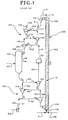
- FIG. 1 is a diagrammatical illustration of an embodiment of the apparatus according to EP 549 891 A1;
- FIG. 2 is a diagrammatical illustration of an embodiment according to the invention;
- FIG. 3 is a partial elevational view of an alternate embodiment of the transport line adsorber shown in FIGS. 1 and 2, and FIG. 3A is a horizontal cross-sectional view taken generally along the line 5-5 in FIG. 3 in the direction of the arrows;
- FIG. 4 is a diagrammatical illustration of a cyclone reactor which is an entrained flow adsorber which may be used as an alternative in the present invention to the transport line adsorber shown in FIGS. 1 and 2, and FIG. 4A is a diagrammatical illustration of the bottom view of the cyclone reactor shown in FIG. 4;
- FIG. 5 is a diagrammatical illustration of a gas suspension adsorber which is an entrained flow adsorber which in accordance with the present invention may be used as an alternative to the transport line adsorber shown in FIGS. 1 and 2; and
- FIG. 6 is a graph showing sulfur content by percent weight versus sorbent particle size or diameter.
-
- Referring now to FIG. 1, apparatus according to EP 549 891 A1 is illustrated diagrammatically and indicated by general
numerical designation 100; -
Apparatus 100 includes a hollow, generally cylindrical and generally vertically oriented transport line adsorber 102 having abottom portion 104 and atop portion 106; the transport line adsorber in accordance with the present invention is one embodiment of an entrained flow adsorber in which the sorbent particles are transported to an elevated position for regeneration by being entrained in the pressurized flue gas flowing upwardly through the adsorber while the particles are simultaneously adsorbing nitrogen oxides and sulfur oxides from the pressurized flue gas. Suitable sorbent particles for adsorbing nitrogen oxides and sulfur oxides from flue gas containing such oxides are utilized and indicated by generalnumerical designation 110. Although in the process of the said EP- 549 891 A1 sorbent particles have a size range of 100 to 210 microns, according to the process of the present inventionsorbent particles 110 will have a size in the range of about 30 to about 500 microns, preferably about 30 to about 250 microns, and more preferably about 50 to about 150 microns, and may be, for example, sorbent particles of the general type disclosed in the above-identified patents incorporated herein by reference. Pressurized flue gas indicated byarrow 108 may be, for example, from a coal-fired or an oil-fired power plant (not shown), or from any other source emitting an effluent gas containing nitrogen oxides and sulfur oxides. Thebottom portion 104 of thetransport line adsorber 102 is provided with an input indicated byarrow 109 through which may be introduced the pressurized flue gas as indicated by thearrow 108 and through which may be introduced thesorbent particles 110 as indicated by thearrow 111. Theinput 109 may be a single input through which both the sorbent particles and the pressurized flue gas are introduced or theinput 109 may be two inputs one for introducing the pressurized flue gas and one for introducing the sorbent particles. - It will be generally understood that the
sorbent particles 110 are transported upwardly through thetransport line adsorber 102 by being entrained in the pressurizedflue gas 108 and that as the sorbent particles are being so transported they adsorb the nitrogen oxides and the sulfur oxides contained in theflue gas 108. Thetop portion 106 of thetransport line adsorber 102 may be provided with anoutput 113 through which the pressurized flue gas and the sorbent particles having the nitrogen oxides and sulfur oxides adsorbed thereto may exit thetransport line adsorber 102. - The height or length of the
transport line 102 is chosen to provide thesorbent particles 110 with sufficient residence or dwell time in the transport line adsorber 102 to permit thesorbent particles 110 to substantially remove substantially all, approximately 90%, nitrogen oxides and sulfur oxides from the pressurized flue gas while the flue gas is transporting thesorbent particles 110 upwardly through the transport line adsorber 102. It has been determined that for sorbent particles having a size of about 50 microns, the length of the transport line adsorber will be about 35 feet and, it has been determined, for sorbent particles having a size of about 150 microns, the length of thetransport line 102 will be about 200-285 feet. - The diameter of the
transport line adsorber 102 will be chosen to provide thepressurized flue gas 108 with a velocity through the transport line adsorber greater than the terminal velocity of thesorbent particles 110, to facilitate the sorbent particles remaining entrained in the flue gas while being transported upwardly through the transport line adsorber by the pressurized flue gas. In the event the pressure of theflue gas 108 is insufficient to transport thesorbent particles 110 upwardly through thetransport line adsorber 102, and insufficient to provide the flue gas with a velocity through the transport line adsorber greater than the terminal velocity of theparticles 110 for a given transport line adsorber diameter, a suitable booster fan may be interposed between the exit of the pressurized flue gas from the power plant (not shown) to boost or increase the pressure of the flue gas sufficiently to entrain the sorbent particles and transport the sorbent particles upwardly through the transport line adsorber and to provide the pressurized flue gas with a velocity through the transport line adsorber greater than the terminal velocity of the sorbent particles. - Upon the
sorbent particles 110 adsorbing the nitrogen oxides and sulfur oxides from the pressurizedflue gas 108 as described above, thesorbent particles 110 become substantially saturated sorbent particles. - A suitable gas-
solid separator 112 is connected to theoutput 113 at thetop portion 106 of thetransport line adsorber 102 and is for receiving and separating the substantially saturated sorbent particles and the pressurizedflue gas 108 and for producing a stream of flue gas indicated byarrow 114 with the nitrogen oxides and sulfur oxides substantially removed therefrom. The gas-solid separator 112 may be a suitable cyclone of the type known to the art and generally referred to as a conical classifier utilizing rotating air for separating finely divided particles from a fluid stream in which the particles are entrained. Accordingly, it will be understood that thecyclone 112 is generally conical in configuration and imparts rotation to the pressurizedflue gas 108 and substantially saturatedsorbent particles 110 to separate the saturated sorbent particles and pressurized flue gas to produce a nitrogen oxide and sulfur oxide free stream of flue gas indicated byarrow 114 and a stream of sorbent particles having the nitrogen oxides and sulfur oxides adsorbed thereto indicated by the solid arrow A1. Alternatively, instead of the gas-solid separator 112, a suitable bag house may be connected to thetop portion 106 of the transport line adsorber 102 for receiving and separating the saturated sorbent particles and the pressurizedgas 108 and for producing the oxide free stream of flue gas indicated byarrow 114. - A first regenerator means comprising a plurality of interconnected cyclones is provided and indicated by general
numerical designation 120. Plurality ofcyclones 120 includes atop cyclone 122, amiddle cyclone 124 and abottom cyclone 126. Such cyclones may each be of the same type ascyclone 112. It will be noted from FIG. 1 that the plurality ofcyclones 120 is disposed in a staggered vertically downward sequence with themiddle cyclone 124 being displaced downwardly and laterally rightwardly with respect totop cyclone 122 and thatbottom cyclone 126 is displaced downwardly and laterally leftwardly with respect to themiddle cyclone 124. Asuitable air heater 130 is provided for heating air to approximately 650° C and for providing heated air to the plurality ofcyclones 120, the specific temperature of the heated air will depend upon the specific regenerant gas used. The interconnections between the plurality ofcyclones 120 and the interconnection between theair heater 130 and the plurality ofcyclones 120 are indicated by the solid arrows 131-136. More particularly, it will be noted that the connection of the output of theair heater 130 to the bottom portion of themiddle cyclone 124 is indicated byarrow 131, that the connection between the bottom portion of themiddle cyclone 124 and the top portion of thebottom cyclone 126 is indicated by arrow 132, that the interconnection between the top portion of thebottom cyclone 126 and the bottom portion of thetop cyclone 122 and the top portion of themiddle cyclone 124 is indicated byarrows middle cyclone 124 to the top portion of thetop cyclone 122 is indicated byarrows solid separator 112 and the inlet of the plurality ofcyclones 120 or the top of themiddle cyclone 124 and the top of thetop cyclone 122 is indicated byline 137. It will be also understood that the directions of the solid arrows 131-136 also indicate the direction of the flow of the heated air from theair heater 130 through the plurality ofcyclones 120. - The outlined arrows shown at the top portion of FIG. 1 indicate the flow of the saturated sorbent particles from the bottom portion or outlet of the gas-
solid separator 112 and through the plurality ofcyclones 120 and to asuitable regenerator 140. It will be understood that the sorbent particles are passed or circulated through the plurality of interconnectedcyclones 120 by a combination of flow of the heated air through thecyclones 120 and gravity. Generally, as the sorbent particles and heated air enter each cyclone of theplurality 120, rotary motion is imparted to the sorbent particles and heated air to contact the sorbent particles with the heated air to heat the sorbent particles sufficiently to desorb or remove the nitrogen oxides therefrom and to separate the removed nitrogen oxides and the sorbent particles; ultimately, an off gas stream of heated air indicated byarrow 142 at the top portion of thetop cyclone 122 carries away the nitrogen oxides removed from the sorbent particles. Heatedgas stream 142 and the removed nitrogen oxides carried thereby may be introduced into the combustion gas stream of the power plant (not shown) producing the pressurizedflue gas 108. More particularly, it will be understood that the sorbent particles from the bottom of the gassolid separator 112 are transported by the heated air indicated byarrow 136 to the top portion of thetop cyclone 122 where rotary motion is imparted to the sorbent particles and heated air to contact the sorbent particles with the heated air to heat the sorbent particles and remove the nitrogen oxides from the sorbent particles and at least partially separate the sorbent particles from the heated air, thereafter the sorbent particles separated by thetop cyclone 122 is transported from the bottom portion of thetop cyclone 122 to the top portion of themiddle cyclone 124 by a combination of gravity and the flow of heated air indicated by thearrow 134 whereupon rotary motion is imparted to the sorbent particles and heated gas by themiddle cyclone 124 to further contact the sorbent particles with heated air to heat the sorbent particles sufficiently to remove nitrogen oxides therefrom and to at least further partially separate the heated air and sorbent particles, thereafter the sorbent particles separated by themiddle cyclone 124 from the heated gas are transported from the bottom portion of themiddle cyclone 124 to the top portion of thebottom cyclone 126 by a combination of gravity and the flow of the heated air indicated by the arrow 132 whereupon rotary motion is imparted to the sorbent particles and heated gas by thebottom cyclone 126 to further contact the sorbent particles with the heated air to heat the sorbent particles sufficiently to further remove nitrogen oxide from the sorbent particles and separate the sorbent particles from the removed nitrogen oxides and heated gas. It will be understood that although three cyclones have been indicated as comprising the plurality ofcyclones 120 that such plurality of three cyclones is merely illustrative of the present invention and that the plurality of interconnectedcyclones 120 will comprise a sufficient number of interconnected cyclones to assure that substantially all of the nitrogen oxides are removed from the sorbent particles upon the sorbent particles being transported or passed through the plurality of cyclones and contacted with the heated air, and the sorbent particles heated to the sulfur regenerative temperature. - Referring again to the plurality of
cyclones 120, it will be noted that the plurality ofcyclones 120 are interconnected in such a manner to cause the flow of sorbent particles therethrough indicated by the outline arrows to be generally or substantially counter to the flow of the heated air therethrough indicated by the solid arrows 132-136. Such counter flow enhances the contacting of the heated air with the sorbent particles to facilitate removal of substantially all of the nitrogen oxides from the sorbent particles. - Heated sorbent particles with the nitrogen oxides removed therefrom, but still having the sulfur oxides adsorbed thereto, are transported over the
line 146, such as by gravity flow, to theregenerator 140 which may be, for example, a moving bed regenerator. Such sorbent particles will be contacted in theregenerator 140 by a suitable regenerant gas which reacts with the SOx and upon contacting the heated sorbent particles having the sulfur oxides adsorbed thereto will remove the sulfur oxides and produce heated sorbent particles having the sulfur oxides removed therefrom and an off gas stream of regenerant gas carrying the removed sulfur oxides away, for example to a suitable Claus plant of the type known to the art. The regenerant gas is indicated byarrow 147 in FIG. 1 and the off gas stream of regenerant gas carrying the sulfur oxides away is indicated by thearrow 148. - A second plurality of interconnected cyclones is provided and indicated by general
numerical designation 150. Plurality ofcyclones 150 includes atop cyclone 152, amiddle cyclone 154 and abottom cyclone 156. Such cyclones may be of the same type as the cyclone comprising the gas-solid separator 112 as described above. It will be noted from FIG. 1 that the plurality ofcyclones 150 is disposed in a staggered vertically downward sequence with themiddle cyclone 154 being displaced downwardly and laterally leftwardly with respect to thetop cyclone 152 and that thebottom cyclone 156 is displaced downwardly and laterally rightwardly with respect to themiddle cyclone 154. Asuitable fan 160 is provided for providing cooling air to the plurality ofcyclones 150; for example the input to thefan 160 may be ambient air indicated byarrow 162. The interconnections between thefan 160 and the plurality ofcyclones 150 are indicated by the solid arrows 161-166. More particularly, it will be noted that the connection of the output of thefan 160 to the bottom portion of themiddle cyclone 154 is indicated byarrow 161, that the connection between the bottom portion of themiddle cyclone 154 and the top portion of thebottom cyclone 156 is indicated byarrow 162, that the interconnection between the top portion of thebottom cyclone 156 and the bottom portion of thetop cyclone 152 and the top portion ofmiddle cyclone 154 is indicated byarrows middle cyclone 154 to the top portion of thetop cyclone 152 is indicated byarrows top cyclone 152 and theair heater 130 is indicated byarrow 167. It will be also understood that the directions of the solid arrows 161-167 also indicate the direction of the flow of the cooling air from thefan 160 through the plurality ofcyclones 150 and to theair heater 130. - The outline arrows shown at the bottom portion of FIG. 1 indicate the flow of the heated regenerated sorbent particles from the bottom of the
regenerator 140 and through the plurality ofcyclones 150 to thebottom portion 104 of thetransport line adsorber 102. It will be understood that the heated regenerated sorbent particles from theregenerator 140 are passed or circulated through the plurality of interconnectedcyclones 150 by a combination of flow of the cooling air indicated by the solid arrows 161-166 through thecyclones 150 and gravity. Generally, as the heated regenerated sorbent particles from theregenerator 140 and the cooling air enter each cyclone of theplurality 150, rotary motion is imparted to the heated regenerated sorbent particles and cooling air to contact the heated regenerated sorbent particles with the cooling air to cool the sorbent particles sufficiently to place them in a suitable condition for readmittance or reentry into thebottom portion 104 of thetransport line adsorber 102 and to separate the heated regenerated sorbent particles and the cooling air from thefan 160; ultimately, an off gas stream of cooling air indicated byarrow 167 at the top portion of thetop cyclone 152 enters theair heater 130 for heating to supply the heated air provided by theair heater 130. More particularly, it will be understood that the heated regenerated particles from the bottom of theregenerator 140 are transported by gravity to the interconnections between the top portion of themiddle cyclone 154 and the top portion of thetop cyclone 152 indicated by thearrows regenerator 140 to the top portion of thetop cyclone 152 by the combination of gravity and the flow of cooling air indicated by thearrow 166. Upon entering the top cyclone 152, rotary motion is imparted to the heated regenerated sorbent particles and the cooling air to contact the heated regenerated sorbent particles with the cooling air to at least partially cool the heated regenerated sorbent particles and to separate such particles from the cooling air; thereafter, the partially cooled regenerated sorbent particles separated by the top cyclone 152 are transported from the bottom portion of the top cyclone 152 to the top portion of the middle cyclone 154 by a combination of gravity and the flow of cooling air indicated by the arrow 164 whereupon rotary motion is imparted to the sorbent and cooling air to further at least partially cool the heated regenerated sorbent particles and to further separate the cooling air and the regenerated sorbent particles, thereafter, the regenerated sorbent particles separated by the middle cyclone 154 is transported from the bottom portion of the middle cyclone 154 to the top portion of the bottom cyclone 156 by a combination of gravity and the flow of cooling air indicated by the arrow 162 whereupon rotary motion is imparted to the cooling air and partially cooled regenerated sorbent particles to further at least partially cool the regenerated sorbent particles and further separate such particles from the cooling air; the now cooled regenerated sorbent particles separated by the bottom cyclone 156 are then transported by gravity to the bottom portion 104 of the transport line adsorber 102 as noted above for recycling. It will be understood that although three cyclones have been indicated as comprising the plurality ofcyclones 150 that such plurality of three cyclones is merely illustrative of the present invention and that the plurality ofinterconnected cyclones 150 will comprise a sufficient number of interconnected cyclones to assure that the heated regenerated sorbent from theregenerator 140 is cooled sufficiently to place the regenerated sorbent in a thermal condition suitable for readmittance or reentry into thebottom portion 104 of thetransport line adsorber 102 for recycling and readsorption of the nitrogen oxides andsulfur oxides 108. The plurality ofcyclones 150 will also be of sufficient number to assure substantially total separation of the regenerated sorbent particles and cooling air from thefan 160. - Referring again to the plurality of
cyclones 150, it will be noted that the plurality ofcyclones 150 are interconnected in such a manner to cause the flow of heated regenerated sorbent particles from theregenerator 140 through the cyclones indicated by the outline arrows to be generally or substantially counter to the flow of the cooling air through the plurality ofcyclones 150 indicated by the solid arrows 162-166. Such counter flow enhances the contacting of the cooling air with the heated regenerated sorbent particles to facilitate substantial cooling of the regenerated sorbent particles and substantial separation of the cooled regenerated sorbent particles from the cooling air from thefan 160. - Referring again to the plurality of
cyclones 120, it will be understood that a cone of sorbent will be present at the bottom portion of thecyclones air heater 130 into the bottom portions of themiddle cyclone 124 and thetop cyclone 122. Similarly, it will be understood, that a cone of heated regenerated sorbent particles will be present at the bottom portions of thetop cyclone 152 and themiddle cyclone 154 of the plurality ofcyclones 150 and that such cone of heated regenerated sorbent particles prevents the entry of the cooling air into the bottom portions of themiddle cyclone 154 and thetop cyclone 152. - It will be understood that the apparatus and process described above and illustrated diagrammatically in FIG. 1, due to the comparative or relatively small size of the sorbent particles 110 (about 30 microns to about 500 microns as noted above) is particularly useful in adsorbing or removing nitrogen oxides and sulfur oxides from flue gas that is relatively free from fly ash. However, in the event that the flue gas, such as
flue gas 108, has a relatively high content of fly ash, the apparatus and process of the present invention using such relatively small sized sorbent particles can still be utilized but such may require the interposition of a bag house or fly ash control apparatus between the source of theflue gas 108 and thelower portion 104 of thetransport line adsorber 102.
In an embodiment of the present invention thetransport line adsorber 102 may be provided with one or more screens suitably mounted transversely and internally thereof as illustrated diagrammatically by therepresentative screen 170 in FIGS. 3 and 3A. Such screen or screens preferentially or selectively slow the flow of the sorbent particles through the transport line adsorber without substantially slowing the flow of the pressurized gas therethrough; such screen or screens preferably will have a mesh number less than 100. By slowing the flow of the sorbent particles through the transport line adsorber relative to the flow of the pressurized gas therethrough, the sorbent particles are exposed to different portions of the pressurized gas and the adsorption of the nitrogen oxides and sulfur oxides by the sorbent particles is enhanced and the oxide removal efficiency increased. - Referring now to FIG. 2, an embodiment of the present invention is shown which is the same as the embodiment shown in FIG. 1 and described above, except that the apparatus shown in FIG. 2 includes a sorbent
particle stream splitter 174 mounted intermediate the output of the gas-solid separator 112 and an input to the plurality ofcyclones 120; the sorbent particle splitter may be any one of several known to the art for splitting or dividing a string of particles into at least two streams of particles. The sorbentparticle stream splitter 174 has aninput 176 connected to the output of the gas-solid separator 112 and afirst output 178 connected to the input of the plurality ofcyclones 120 and asecond output 179 connected to asuitable line 180 connecting thesecond output 179 of the sorbentparticle stream splitter 174 to thebottom portion 104 of thetransport line adsorber 102 to return a portion of the sorbent particles having the nitrogen oxides and sulfur oxides adsorbed thereto to the bottom input portion of thetransport line adsorber 102 for retransportation upwardly through the transport line adsorber by the pressurized flue gas as described above. This return or recycling of a portion of the sorbent particles increases the nitrogen oxides and sulfur oxides adsorbed by the returned or recycled sorbent particles and enhances the efficiency of the oxide removal apparatus and process. In the preferred embodiment, about 30% of the sorbent particles from the gas-solid separator 112 is diverted to the plurality of cyclones by the sorbent particle stream splitter for regeneration and about 70% is returned to thetransport line adsorber 102 for recycling. - As alternatives to the
transport line adsorber 102, FIGS. 1 and 2, other entrained flow adsorbers may be used in accordance with the present invention, such as for example, the cyclone reactor shown in FIG. 4 and indicated by generalnumerical designation 200 and the gas suspension adsorber shown in FIG. 5 and indicated by generalnumerical designation 300. Referring to FIG. 4, thecyclone reactor 200 includes a hollow generally vertically orientedvessel 210 having anoutput 211 connected to a gas-solid separator 112, such as the gas-solid separator 112 shown in FIGS. 1 and 2 and described above, and the output of which gas-solid separator is connected to the input of a sorbentparticle stream splitter 174 which may be the sorbentparticle stream splitter 174 shown in FIG. 2 and described above; one stream from one output of the sorbent particle stream splitter flows to the plurality ofinterconnected cyclones 120 shown in FIGS. 1 and 2, as indicated byarrow 220, and the other stream from the other output of the sorbentparticle stream splitter 174 is returned to the input of thecyclone reactor 200 as indicated by thearrow 222 for recycling and enhanced oxide removal as described above. Thevessel 210 of thecyclone reactor 200 is provided at its bottom portion with a tangentially orientedinput 212 through which thepressurized flue gas 108 enters and which gas imparts a generally spiral upward flow to the pressurized flue gas as indicated by thespiral arrow 218. Fresh sorbent is introduced into aninput port 214 located at the bottom of thevessel 210 and which fresh sorbent particles are indicated by the arrow 216. The sorbent particles introduced at theinput port 214 are transported upwardly and provided with the spiral flow as indicated by thearrow 218 to transport the sorbent particles upwardly and to expose the sorbent particles to the flue gas and to cause the sorbent particles to adsorb the nitrogen oxides and sulfur oxides from the flue gas. The flue gas carrying the sorbent particles having the oxides adsorbed thereto flow to the gas-solid separator 112 out of thecyclone reactor output 211 where they are separated as described above in connection with the operation of the gas-solid separator 112. - The cyclone reactor with internal separation and axial recirculation disclosed in US-A 4,881,476 also may be used as an alternative to the
transport line adsorber 102 shown in FIGS. 1 and 2 and described above. - Referring now to FIG. 5, the
gas suspension adsorber 300 shown in FIG. 5 is a diagrammatical illustration of the gas suspension adsorber shown and described in Clean Coal Technology Demonstration Program, Program Update 1991, published February, 1992 by the U.S. Department of Energy. Thegas suspension adsorber 300 includes a generally hollowvertical reactor vessel 310 in which thesorbent particles 110 come in contact with or are exposed to the pressurized flue gas entering the bottom portion of thevessel 310, as indicated byarrows 108, and thesorbent particles 110 are transported upwardly by the pressurized flue gas during which time thesorbent particles 110 adsorb the nitrogen oxides and sulfur oxides contained in theflue gas 108. The sorbent particles having such oxides adsorbed thereto and the pressurized flue gas exit thevessel 110 through theupper output 311 and enter the gas-solid separator 112 which separates the flue gas and the sorbent particles having the oxides adsorbed thereto to provide an offstream 114 free of such oxides and a stream of sorbent particles having the oxides adsorbed thereto which exit the gas-solid separator 112 and enter thesorbent particle splitter 174 as illustrated in FIG. 5 by thearrow 326. Thesorbent particle splitter 174 functions in the same manner as thesorbent particle splitter 174 shown in FIG. 2 and described above to provide two streams of sorbent particles having the oxides adsorbed thereto one of which streams, indicated byarrow 320, goes to the plurality ofcyclones 120 shown in FIGS. 1 and 2 and the other stream, as indicated by thearrow 322, is returned to the input 314 provided at the bottom portion of thevessel 310 for recycling and increased oxide removal efficiency as described above. Fresh sorbent particles are also introduced into the input 314 as indicated by thearrow 316. - The above-noted sorbent may be composed of γ-alumina substrate on which sodium is deposited. The particles or beads may be made using one of several processes depending upon the bead size and other factors. The process may begin with the formation of a paste or water and the very small particles of alumina (about 10µ in diameter). In the process to make beads in the 50 to 150 micron range, the paste is sprayed through a nozzle into a spray dryer. The small beads produced by the nozzle are dried as they fall through air to the bottom of a spray chamber where they are collected and removed.
- In Fig. 6 the sulfur content by percent weight after adsorption is compared with sulfur content of sorbent particles of various sizes from 0 to 2500 microns, respectively; the sulfur carrying or adsorbing capacity for sorbent particles of about 500 microns particle size is about 40 % greater than for the sorbent particles of 1500 microns particle size.
Claims (8)
- Apparatus for utilizing sorbent particles to adsorb and remove nitrogen oxides and sulfur oxides from flue gas, comprising:entrained flow adsorber means (102) for receiving said sorbent particles and said flue gas and for entraining said particles in said flue gas to expose said particles to said flue gas and to cause said sorbent particles to adsorb and substantially remove said oxides from said flue gas, said adsorber means (102) having an input means (109) for receiving said sorbent particles and said flue gas and output means (113) through which said flue gas and said sorbent particles having said oxides adsorbed thereto exit;gas-solid separator means (112) for receiving said flue gas and said sorbent particles having said oxides adsorbed thereto and for separating said gas and said particles having said oxides adsorbed thereto into a stream of flue gas having said oxides substantially removed therefrom and a stream of sorbent particles having said oxides adsorbed thereto, said gas-solid separator means (112) having input means connected to the output means (113) of said adsorber means (102), having first output means (114) through which said stream flue gas having said oxides substantially removed therefrom exit and second output means (176) through which said stream of sorbent particles having said oxides adsorbed thereto exit;first regenerator means (120) for receiving said stream of sorbent particles having said oxides adhered thereto and for removing said nitrogen oxides therefrom, said first regenerator means (120) having input means (137) communicating with said second output means (176) of said separator means (112) and having output means;second regenerator means (140) for receiving said stream of sorbent particles having said sulfur oxides adsorbed thereto and said nitrogen oxides removed therefrom and for removing said sulfur oxides from said first stream of sorbent particles, said second regenerator (140) having input means (146) connected to said output means of said first regenerator (120) and having output means connected to said input means of said adsorber means
characterized by sorbent particle stream splitter means (174) for receiving said stream of sorbent particles having said oxides adsorbed thereto and for dividing said stream into first and second streams of sorbent particles having said oxides adhered thereto, said particle stream splitter means (174) having input means connected to the second output means (176) of said gas-solid separator means (112) and having two output means (178, 179), said first stream of sorbent particles having said oxides adhered thereto exiting said first output means (178) and said second stream of sorbent particles having said oxides adhered thereto exiting said second output means (179) and connecting means (180) interconnecting said second output means (179) of said particle stream splitter means (174) to said input means (109) of said adsorber means (102) to cause said second stream of sorbent particles having said oxides adhered thereto to enter said input means (109) of said adsorber means (102), whereby said input means (137) of said first regenerator means (120) is connected to said first output means (178) of said particle stream splitter means (174). - The apparatus according to claim 1, wherein said entrained flow adsorber means comprise a hollow generally cylindrical and generally vertically oriented transport line adsorber (102).
- The apparatus according to claim 1, wherein said entrained flow adsorber means comprise a cyclone reactor (200).
- The apparatus according to claim 1, wherein said entrained flow adsorber means comprise a gas suspension adsorber (300).
- The apparatus according to claim 2 wherein said transport line adsorber (102) is provided with means (170) mounted internally thereof for slowing the flow of said sorbent particles therethrough relative to the flow of said flue gas therethrough to enhance the adsorption of said oxides by said sorbent particles.
- The apparatus according to claim 5 wherein said means (170) mounted internally of said transport line adsorber (102) comprise at least one screen mounted internally and transversely of said transport line adsorber.
- Process for utilizing cooled regenerated sorbent particles to substantially remove nitrogen oxides and sulfur oxides from pressurized flue gas, comprising the steps of:providing sorbent particles suitable for adsorbing nitrogen oxides and sulfur oxides from said flue gas;transporting said sorbent particles through entrained flow adsorber means utilizing said pressurized flue gas to cause said sorbent particles to substantially adsorb said nitrogen oxides and said sulfur oxides from said flue gas while said sorbent particles are being transported through said entrained flow adsorber means by said pressurized flue gas;separating said sorbent particles having said oxides adsorbed thereto from said flue gas to provide a stream of substantially nitrogen oxide and sulfur oxide free flue gas and to provide sorbent particles having said oxides adsorbed thereto;providing a source of heated gas;passing at least some said sorbent particles having said oxides adsorbed thereto through a regenerator meansutilizing said heated gas and gravity to heat said sorbent particles to remove said nitrogen oxides therefrom and to separate said sorbent particles and remove nitrogen oxides and to produce an off gas stream of heated gas carrying away said nitrogen oxides and to provide heated sorbent particles having said sulfur oxides adsorbed thereto;contacting said heated sorbent particles having said sulfur oxides adsorbed thereto with a regenerant gas to substantially remove said sulfur oxides therefrom and to produce heated regenerated sorbent particles and an off gas stream of regenerant gas carrying away said sulfur oxides removed from said heated regenerated sorbent particles;providing a cooling gas;passing said heated regenerated sorbent particles through a plurality of interconnected cyclones utilizing said cooling gas and gravity to cool said sorbent particles and to separate said sorbent particles from said cooling gas to produce cooled regenerated sorbent particles; andreturning said cooled regenerated sorbent particles to said entrained flow adsorber means and repeating said steps for removing said nitrogen oxides and said sulfur oxides from said pressurized flue gas, characterized in that said process includes the further step, intermediate said step of separating said sorbent particles having said oxides adsorbed thereto from said flue gas and said step of providing a source of heated gas, of returning a portion of said sorbent particles having said oxides adsorbed thereto to said entrained flow adsorber means to enhance the adsorption of said oxides by said portion of returned sorbent particles.
- The process according to claim 7 wherein the sorbent particles are provided of an average size in the range of about 30 to about 500 microns.
Applications Claiming Priority (2)
| Application Number | Priority Date | Filing Date | Title |
|---|---|---|---|
| US166203 | 1993-12-13 | ||
| US08/166,203 US5383955A (en) | 1991-12-02 | 1993-12-13 | Nitrogen oxides and sulfur oxides removal utilizing transport line adsorber |
Publications (3)
| Publication Number | Publication Date |
|---|---|
| EP0657203A2 EP0657203A2 (en) | 1995-06-14 |
| EP0657203A3 EP0657203A3 (en) | 1995-11-29 |
| EP0657203B1 true EP0657203B1 (en) | 1999-03-03 |
Family
ID=22602242
Family Applications (1)
| Application Number | Title | Priority Date | Filing Date |
|---|---|---|---|
| EP94118446A Expired - Lifetime EP0657203B1 (en) | 1993-12-13 | 1994-11-24 | Nitrogen oxides and sulfur oxides removal utilizing transport line absorber |
Country Status (3)
| Country | Link |
|---|---|
| US (1) | US5383955A (en) |
| EP (1) | EP0657203B1 (en) |
| DE (1) | DE69416790D1 (en) |
Families Citing this family (12)
| Publication number | Priority date | Publication date | Assignee | Title |
|---|---|---|---|---|
| US5500196A (en) * | 1993-08-16 | 1996-03-19 | The Babcock & Wilcox Company | Method of reagent and oxidation air delivery |
| US5426083A (en) * | 1994-06-01 | 1995-06-20 | Amoco Corporation | Absorbent and process for removing sulfur oxides from a gaseous mixture |
| US5843862A (en) * | 1994-06-01 | 1998-12-01 | Amoco Corporation | Process for manufacturing an absorbent composition |
| US5904750A (en) * | 1995-08-22 | 1999-05-18 | Cowles; Harold R. | VOC control/solvent recovery system |
| US5676738A (en) * | 1995-08-22 | 1997-10-14 | Cioffi; Lawrence | VOC control/solvent recovery system |
| US7410524B2 (en) * | 2003-06-19 | 2008-08-12 | Tower Paul M | Regenerable purification system for removal of siloxanes and volatile organic carbons |
| US7393381B2 (en) | 2003-06-19 | 2008-07-01 | Applied Filter Technology, Inc. | Removing siloxanes from a gas stream using a mineral based adsorption media |
| US9657937B2 (en) * | 2010-08-23 | 2017-05-23 | Saudi Arabian Oil Company | Steam generation system having multiple combustion chambers and dry flue gas cleaning |
| US9073005B2 (en) * | 2011-06-09 | 2015-07-07 | Sri International | Falling microbead counter-flow process for separating gas mixtures |
| CN105565285A (en) * | 2015-12-25 | 2016-05-11 | 杨皓 | Method for using pressure swing adsorption process to extract pure nitrogen from flue gas deacidification exhaust |
| CN113750741A (en) * | 2021-09-02 | 2021-12-07 | 中国华能集团有限公司 | Flue gas purification system with fluidized bed reactor |
| CN119618759A (en) * | 2024-12-02 | 2025-03-14 | 国网山东省电力公司电力科学研究院 | A multi-transformer non-electrical gas online monitoring device |
Family Cites Families (21)
| Publication number | Priority date | Publication date | Assignee | Title |
|---|---|---|---|---|
| US2389236A (en) * | 1940-12-31 | 1945-11-20 | Standard Oil Dev Co | Catalytic conversion system |
| US2397566A (en) * | 1943-09-29 | 1946-04-02 | Lummus Co | Gas adsorption |
| US2992065A (en) * | 1958-07-31 | 1961-07-11 | Reinluft G M B H | Process for removing sulfur oxides from gases |
| US3563704A (en) * | 1968-08-13 | 1971-02-16 | Westvaco Corp | Removal and recovery of sulfur oxides from gases |
| US3913253A (en) * | 1970-10-16 | 1975-10-21 | Bergwerksverband Gmbh | Process of removing sulfur oxide from exhaust gases |
| US3727376A (en) * | 1971-10-20 | 1973-04-17 | Oldham E | Process for the separation of a gaseous mixture |
| GB1474184A (en) * | 1973-05-08 | 1977-05-18 | Shell Int Research | Process for removing sulphur oxides and particulate matter from waste gases and apparatus therefor |
| US4004885A (en) * | 1973-05-08 | 1977-01-25 | Shell Oil Company | Removal of sulfur oxides and particulate matter from waste gas streams |
| US3976446A (en) * | 1975-01-22 | 1976-08-24 | Thermo-Mist Company | Sulfur removal from high temperature fuel gas generated by gasification |
| US4215101A (en) * | 1978-06-13 | 1980-07-29 | Fried. Krupp Gesellschaft Mit Beschrankter Haftung | Method and apparatus for performing chemical and/or physical treatments |
| JPS6037047B2 (en) * | 1979-03-09 | 1985-08-23 | 住友重機械工業株式会社 | Regeneration method of activated carbon for desulfurization |
| US4692318A (en) * | 1984-08-13 | 1987-09-08 | Amoco Corporation | Process for simultaneously removing nitrogen oxides, sulfur oxides, and particulates |
| US4609539A (en) * | 1984-08-13 | 1986-09-02 | Standard Oil Company (Indiana) | Process for simultaneously removing sulfur oxides and particulates |
| US4612177A (en) * | 1984-08-13 | 1986-09-16 | Standard Oil Company (Indiana) | Removal of sulfur oxides and particulates with copper-containing absorbers |
| US4755499A (en) * | 1984-10-12 | 1988-07-05 | Noxso Corporation | Sorbent for removing nitrogen oxides, sulfur oxides and hydrogen sulfide from gas streams |
| US4940569A (en) * | 1984-10-12 | 1990-07-10 | Noxso Corporation | Sorbent and processes for removing nitrogen oxides, sulfur oxides and hydrogen sulfide from gas streams |
| US4798711A (en) * | 1984-10-12 | 1989-01-17 | Noxso Corporation | Processes for removing nitrogen oxides, sulfur oxides and hydrogen sulfide from gas streams |
| US4917875A (en) * | 1986-05-27 | 1990-04-17 | Englehard Corporation | Gas/solid contact method for removing sulfur oxides from gases |
| DK339588A (en) * | 1987-09-03 | 1989-03-04 | Smidth & Co As F L | PROCEDURE AND PLANT FOR SIMILAR CLEANING OF ROEGGAS AND FLYING BASKET FOR Sulfur Oxides and Nitrogen Oxides |
| US4881476A (en) * | 1988-07-26 | 1989-11-21 | The United States Of America As Represented By The United States Department Of Energy | Cyclone reactor with internal separation and axial recirculation |
| ES2096704T3 (en) * | 1991-12-02 | 1997-03-16 | Noxso Corp | ELIMINATION OF NITROGEN OXIDES AND SULFUR OXIDES USING AN ABSORBENT SYSTEM IN TRANSPORT DUCT. |
-
1993
- 1993-12-13 US US08/166,203 patent/US5383955A/en not_active Expired - Fee Related
-
1994
- 1994-11-24 EP EP94118446A patent/EP0657203B1/en not_active Expired - Lifetime
- 1994-11-24 DE DE69416790T patent/DE69416790D1/en not_active Expired - Lifetime
Also Published As
| Publication number | Publication date |
|---|---|
| DE69416790D1 (en) | 1999-04-08 |
| EP0657203A3 (en) | 1995-11-29 |
| US5383955A (en) | 1995-01-24 |
| EP0657203A2 (en) | 1995-06-14 |
Similar Documents
| Publication | Publication Date | Title |
|---|---|---|
| US4469493A (en) | Method and apparatus for the purification of gases which contain solid and gaseous impurities | |
| US1825707A (en) | Method of adsorbing a gas in a solid adsorbent | |
| US3907971A (en) | Method of removing HF from gases | |
| US5383955A (en) | Nitrogen oxides and sulfur oxides removal utilizing transport line adsorber | |
| US5198001A (en) | Apparatus and process for removing organic compounds from a gas stream | |
| US8709348B1 (en) | Reduced sorbent utilization for circulating dry scrubbers | |
| JPH05237329A (en) | Method and device for separating gas | |
| GB2024041A (en) | Process and apparatus for the purification of waste air | |
| CN100404989C (en) | A kind of engineering plastic air flow and fluidized bed drying method with nitrogen circulation | |
| CN108339371A (en) | Continuous CO absorption2Device and method | |
| US4917875A (en) | Gas/solid contact method for removing sulfur oxides from gases | |
| JPH0564718A (en) | Concentration method and device | |
| EP0549891B1 (en) | Nitrogen oxides and sulfur oxides removal utilizing transport line adsorber | |
| US4081508A (en) | Process for reducing flue gas contaminants from fluid cracking catalyst regenerator | |
| US6251164B1 (en) | Fluid separation process and separation system therefor | |
| US4710364A (en) | Continuous recovery of sulfur oxide from flue gas | |
| US2578674A (en) | Nitric oxide recovery system | |
| JPH0290913A (en) | Air purification methods and devices | |
| US5017349A (en) | Method for desulfurization of flue gases | |
| CN106540510A (en) | It is a kind of can Detachment Activity charcoal fluidised bed adsorption dichloroethanes technique | |
| US5376165A (en) | Method for the treatment of gases, ellipsoidal packing and its use | |
| CN107029534A (en) | A kind of broken burnt removing multiple pollutant of wide particle diameter and its circulatory system of regeneration | |
| CN106422715A (en) | Integrated wet-process flue gas purifying system and flue gas purifying method | |
| JPH07284624A (en) | Continuous recovery device of specific gas by molecular sieve adsorbent using fluidized bed | |
| JPH0623222A (en) | Method and apparatus for treating waste gas |
Legal Events
| Date | Code | Title | Description |
|---|---|---|---|
| PUAI | Public reference made under article 153(3) epc to a published international application that has entered the european phase |
Free format text: ORIGINAL CODE: 0009012 |
|
| AK | Designated contracting states |
Kind code of ref document: A2 Designated state(s): BE DE DK ES GB IT SE |
|
| PUAL | Search report despatched |
Free format text: ORIGINAL CODE: 0009013 |
|
| AK | Designated contracting states |
Kind code of ref document: A3 Designated state(s): BE DE DK ES GB IT SE |
|
| 17P | Request for examination filed |
Effective date: 19951111 |
|
| 17Q | First examination report despatched |
Effective date: 19970523 |
|
| GRAG | Despatch of communication of intention to grant |
Free format text: ORIGINAL CODE: EPIDOS AGRA |
|
| GRAG | Despatch of communication of intention to grant |
Free format text: ORIGINAL CODE: EPIDOS AGRA |
|
| GRAH | Despatch of communication of intention to grant a patent |
Free format text: ORIGINAL CODE: EPIDOS IGRA |
|
| GRAH | Despatch of communication of intention to grant a patent |
Free format text: ORIGINAL CODE: EPIDOS IGRA |
|
| GRAA | (expected) grant |
Free format text: ORIGINAL CODE: 0009210 |
|
| AK | Designated contracting states |
Kind code of ref document: B1 Designated state(s): BE DE DK ES GB IT SE |
|
| PG25 | Lapsed in a contracting state [announced via postgrant information from national office to epo] |
Ref country code: SE Free format text: THE PATENT HAS BEEN ANNULLED BY A DECISION OF A NATIONAL AUTHORITY Effective date: 19990303 Ref country code: IT Free format text: LAPSE BECAUSE OF FAILURE TO SUBMIT A TRANSLATION OF THE DESCRIPTION OR TO PAY THE FEE WITHIN THE PRE;WARNING: LAPSES OF ITALIAN PATENTS WITH EFFECTIVE DATE BEFORE 2007 MAY HAVE OCCURRED AT ANY TIME BEFORE 2007. THE CORRECT EFFECTIVE DATE MAY BE DIFFERENT FROM THE ONE RECORDED.SCRIBED TIME-LIMIT Effective date: 19990303 Ref country code: ES Free format text: THE PATENT HAS BEEN ANNULLED BY A DECISION OF A NATIONAL AUTHORITY Effective date: 19990303 Ref country code: BE Free format text: LAPSE BECAUSE OF FAILURE TO SUBMIT A TRANSLATION OF THE DESCRIPTION OR TO PAY THE FEE WITHIN THE PRESCRIBED TIME-LIMIT Effective date: 19990303 |
|
| REF | Corresponds to: |
Ref document number: 69416790 Country of ref document: DE Date of ref document: 19990408 |
|
| PG25 | Lapsed in a contracting state [announced via postgrant information from national office to epo] |
Ref country code: DK Free format text: LAPSE BECAUSE OF FAILURE TO SUBMIT A TRANSLATION OF THE DESCRIPTION OR TO PAY THE FEE WITHIN THE PRESCRIBED TIME-LIMIT Effective date: 19990603 |
|
| PG25 | Lapsed in a contracting state [announced via postgrant information from national office to epo] |
Ref country code: DE Free format text: LAPSE BECAUSE OF FAILURE TO SUBMIT A TRANSLATION OF THE DESCRIPTION OR TO PAY THE FEE WITHIN THE PRESCRIBED TIME-LIMIT Effective date: 19990605 |
|
| PLBE | No opposition filed within time limit |
Free format text: ORIGINAL CODE: 0009261 |
|
| STAA | Information on the status of an ep patent application or granted ep patent |
Free format text: STATUS: NO OPPOSITION FILED WITHIN TIME LIMIT |
|
| 26N | No opposition filed | ||
| PGFP | Annual fee paid to national office [announced via postgrant information from national office to epo] |
Ref country code: GB Payment date: 20011128 Year of fee payment: 8 |
|
| REG | Reference to a national code |
Ref country code: GB Ref legal event code: IF02 |
|
| PG25 | Lapsed in a contracting state [announced via postgrant information from national office to epo] |
Ref country code: GB Free format text: LAPSE BECAUSE OF NON-PAYMENT OF DUE FEES Effective date: 20021124 |
|
| GBPC | Gb: european patent ceased through non-payment of renewal fee |