EP0656700A1 - Système optique pour la transmission d'un signal à plusieurs étages - Google Patents
Système optique pour la transmission d'un signal à plusieurs étages Download PDFInfo
- Publication number
- EP0656700A1 EP0656700A1 EP94118819A EP94118819A EP0656700A1 EP 0656700 A1 EP0656700 A1 EP 0656700A1 EP 94118819 A EP94118819 A EP 94118819A EP 94118819 A EP94118819 A EP 94118819A EP 0656700 A1 EP0656700 A1 EP 0656700A1
- Authority
- EP
- European Patent Office
- Prior art keywords
- optical
- electrical
- output
- signal
- decision unit
- Prior art date
- Legal status (The legal status is an assumption and is not a legal conclusion. Google has not performed a legal analysis and makes no representation as to the accuracy of the status listed.)
- Ceased
Links
Images

Classifications
-
- H—ELECTRICITY
- H04—ELECTRIC COMMUNICATION TECHNIQUE
- H04L—TRANSMISSION OF DIGITAL INFORMATION, e.g. TELEGRAPHIC COMMUNICATION
- H04L25/00—Baseband systems
- H04L25/38—Synchronous or start-stop systems, e.g. for Baudot code
- H04L25/40—Transmitting circuits; Receiving circuits
- H04L25/49—Transmitting circuits; Receiving circuits using code conversion at the transmitter; using predistortion; using insertion of idle bits for obtaining a desired frequency spectrum; using three or more amplitude levels ; Baseband coding techniques specific to data transmission systems
- H04L25/4917—Transmitting circuits; Receiving circuits using code conversion at the transmitter; using predistortion; using insertion of idle bits for obtaining a desired frequency spectrum; using three or more amplitude levels ; Baseband coding techniques specific to data transmission systems using multilevel codes
-
- H—ELECTRICITY
- H04—ELECTRIC COMMUNICATION TECHNIQUE
- H04B—TRANSMISSION
- H04B10/00—Transmission systems employing electromagnetic waves other than radio-waves, e.g. infrared, visible or ultraviolet light, or employing corpuscular radiation, e.g. quantum communication
- H04B10/50—Transmitters
-
- H—ELECTRICITY
- H04—ELECTRIC COMMUNICATION TECHNIQUE
- H04B—TRANSMISSION
- H04B10/00—Transmission systems employing electromagnetic waves other than radio-waves, e.g. infrared, visible or ultraviolet light, or employing corpuscular radiation, e.g. quantum communication
- H04B10/50—Transmitters
- H04B10/501—Structural aspects
- H04B10/503—Laser transmitters
- H04B10/504—Laser transmitters using direct modulation
-
- H—ELECTRICITY
- H04—ELECTRIC COMMUNICATION TECHNIQUE
- H04B—TRANSMISSION
- H04B10/00—Transmission systems employing electromagnetic waves other than radio-waves, e.g. infrared, visible or ultraviolet light, or employing corpuscular radiation, e.g. quantum communication
- H04B10/50—Transmitters
- H04B10/516—Details of coding or modulation
- H04B10/54—Intensity modulation
- H04B10/541—Digital intensity or amplitude modulation
-
- H—ELECTRICITY
- H04—ELECTRIC COMMUNICATION TECHNIQUE
- H04J—MULTIPLEX COMMUNICATION
- H04J7/00—Multiplex systems in which the amplitudes or durations of the signals in individual channels are characteristic of those channels
Definitions
- the invention relates to an optical transmission system according to the preamble of claim 1.
- the invention also relates to an optical transmitter with an electrical-optical converter according to the preamble of claim 2.
- the invention relates to a decision-making circuit for use in the transmission system according to the invention. It is the subject of claims 4 to 6.
- Optical transmission systems with the features listed in the preamble of claim 1 and the optical transmitter used therein are well known, for. B. from: EP-A2-554 736.
- An electrical-optical converter is shown there on the transmission side, which emits an optical signal frequency-modulated by an electrical digital signal.
- the transmission takes place via an optical fiber to an optical receiver, which has an optical-electrical converter and a decision maker.
- the digital signal is recovered with the decision maker.
- the invention has for its object to provide an optical transmission system in which signals can be transmitted with a high bit rate. This object is achieved as indicated in claim 1.
- the invention is also based on the object of specifying an optical transmitter for such a system. This object is achieved as indicated in claim 2. Developments of the invention are specified in the subclaims.
- An advantage of the invention is that the bit repetition frequency can be increased in this optical transmission system with unchanged lasers and unchanged control electronics.
- FIG. 1 An optical transmission system is shown in FIG. 1. It has an optical transmitter 1, a transmission link with an optical waveguide 5 and an optical receiver 2.
- the optical transmitter has a power adder 3, an electrical-optical converter 4, which is preferably a semiconductor laser, two inputs 12, 13 and an output 11. Via the input 13, the power adder 3 receives a first electrical digital signal V 1 and via the input 12 second electrical digital signal V2 supplied. The power adder 3 is connected to the semiconductor laser 4. Its optical signal is coupled into the optical waveguide 5 at the output 11.
- a power adder 3 an electrical-optical converter 4, which is preferably a semiconductor laser, two inputs 12, 13 and an output 11. Via the input 13, the power adder 3 receives a first electrical digital signal V 1 and via the input 12 second electrical digital signal V2 supplied.
- the power adder 3 is connected to the semiconductor laser 4. Its optical signal is coupled into the optical waveguide 5 at the output 11.
- the power adder 3 forms from the digital signals V1, V2 by bitwise addition an electrical multi-stage signal V, the formation of which is explained in more detail in FIG. 2.
- the semiconductor laser is modulated here directly by the electrical multi-stage signal V. It is also possible that instead of the directly modulated laser there is a device in which continuous light emitted by a semiconductor laser is modulated externally by an optical modulator. In this case, the electrical multi-stage signal V is fed to the optical modulator.
- the multistage signal V modulates the frequency or amplitude of the light emitted by the electrical-optical converter 4.
- This multi-stage signal V is particularly advantageous in a transmission system in which signals are transmitted in a frequency-modulated manner.
- Such a system is known from EP-A2-544 736 mentioned above.
- the optical receiver 2 has an optical-electrical converter 6 which e.g. is a PIN photodiode, a decision circuit 7, an optical input 8 and two electrical outputs 9, 10.
- the electrical output of the photodiode 6 is via one or more amplifiers (not shown) with the decision circuit 7 and this with two outputs 9 , 10 connected.
- the optical signal reaching the optical receiver is received at the input 8 by the photodiode 6 and converted into an electrical multistage signal V, which is fed to the decision circuit 7.
- This electrical multi-stage signal V is evaluated by the decision circuit 7.
- the electrical digital signals V1, V2 are shown at the inputs 12, 13 of the optical transmitter 1 and at the outputs 9, 10 of the optical receiver 2.
- the electrical multi-stage signal V is shown at the connection between the power adder 3 and the semiconductor laser 4. For all signals, the course of the amplitude is shown as a function of time.
- a multi-stage signal V which is a four-stage signal here, is shown, which is composed of two electrical digital signals V1, V2. Both Signals have the same bit duration.
- the digital signal V1 has the states "1, 0, 1, 0, 0, 1, 1, 0" and the digital signal V2 has the states "0, 1, 1, 0, 1, 1, 0, 1".
- the amplitude of the digital signal V2 is twice as large as that of the digital signal V1.
- the amplitude as a function of time is also shown.
- That the amplitude of the digital signal V2 is twice as large as that of the digital signal V1, z. B. can be achieved in that the digital signal V1 is attenuated by a factor of 2 with respect to V2. This can be done by an attenuator in or outside the optical transmitter 1. However, this does not matter for the function. It is important that the amplitudes are different.
- the bit duration in the resulting four-stage signal V corresponds to the bit duration of the digital signals V1, V2.
- This four-stage signal thus contains twice the information in one bit duration, namely that of the two digital signals V1, V2. This makes it possible to increase the amount of information to be transmitted by a factor of 2, which corresponds to a doubling of the bit rate.
- decision-making units consist of a comparator and a D flip-flop. Comparators and how they work are well known, e.g. B. from: U. Tietze, C. Schenk: “Semiconductor circuit technology", 8th edition, Springer-Verlag 1986, chapter 8.5.1, page 178. When the input voltage difference passes zero, the output voltage assumes a logic state "1".
- the four-stage signal is fed to the "(+) input” of the comparator and the "(-) input” the corresponding threshold value.
- the output voltage thus assumes a logic state "1", if the four-stage signal V is greater than the respective threshold value.
- the D flip-flop is used to store the respective logic state. The processing of signals takes place synchronously to a uniform clock. To simplify matters, no clock feed is shown in the figures.
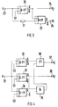
- FIG. 3 shows a first exemplary embodiment of a decision-making circuit 7. So that the decision-making circuit 7 present in the optical receiver 2 can recover the two digital signals V 1, V 2 from the four-stage signal V, a threshold value S1 is to be defined. In Fig. 2 this lies in the middle of the four-stage signal V.
- the decision circuit 7 wins back from the four-stage signal V the digital signal V2 according to the proviso that V2 always has the state "1" when the threshold S1 is exceeded.
- the decision circuit 7 has an input 23 for the four-stage signal V, an output 25 for the digital signal V1, an output 24 for the digital signal V2, a first 20 and second decision unit 22 and a delay gate 21st
- Each decision unit 20, 22 has a first output Q and a second output Q ⁇ which is an inverting output.
- the delay gate 21 delays the four-stage signal by the time required for its processing in the first decision unit 20. This is necessary because the difference V-V2 is formed to recover the digital signal V1; V2 must therefore already be recovered at the time the difference is formed.
- the first decision unit 20 compares the four-stage signal V with the threshold value S1. If this is exceeded, the digital signal V2 exits at its first output Q. This corresponds to the output 24 of the decision circuit 7.
- the second decision unit 22 is connected to the first output Q of the decision unit 20 and to the delay gate 21. via which the four-stage signal V is supplied. By the decision unit 22, the already mentioned difference formation V-V2 takes place, so that at its first output Q, which corresponds to the output 25 of the decision circuit 7, the digital signal V1 emerges.
- FIG. 4 A second exemplary embodiment of the decision circuit 7 is shown in FIG. 4. So that the decision circuit 7 present in the optical receiver 2 can recover the two digital signals V 1, V 2 from the four-stage signal V, a first S0, a second S1 and a third threshold value S2 are to be defined. In Fig. 2, the threshold values are set so that they are in the middle between the individual stages.
- the decision circuit 7 has an input 31 for the four-stage signal V, an output 37 for the digital signal V1, an output 38 for the digital signal V2, a first 32, second 33 and third decision unit 34, an "AND" gate 35 and an "OR” gate 36.
- the first decision unit 32 compares the four-stage signal V with the upper threshold value S2.
- the second decision unit 33 compares the four-stage signal V with the middle threshold S1, and the third decision unit 34 compares the four-stage signal V with the lower threshold S0.
- the digital signal V2 exits.
- the second exit Q ⁇ the second decision unit 33 and the first output Q of the third decision unit 34 are connected to the "AND" gate 35, the output of which is connected to the "OR” gate 36.
- the "OR” gate 36 is also connected to the first output Q of the first decision unit 32, so that the digital signal V 1 exits at the output of the "OR" gate 36. This output corresponds to the output 37 of the decision circuit 7 and that at which the digital signal V2 emerges corresponds to the output 38.
Applications Claiming Priority (2)
| Application Number | Priority Date | Filing Date | Title |
|---|---|---|---|
| DE4341408 | 1993-12-04 | ||
| DE4341408A DE4341408A1 (de) | 1993-12-04 | 1993-12-04 | Optisches System zur Übertragung eines Mehrstufensignals |
Publications (1)
| Publication Number | Publication Date |
|---|---|
| EP0656700A1 true EP0656700A1 (fr) | 1995-06-07 |
Family
ID=6504208
Family Applications (1)
| Application Number | Title | Priority Date | Filing Date |
|---|---|---|---|
| EP94118819A Ceased EP0656700A1 (fr) | 1993-12-04 | 1994-11-30 | Système optique pour la transmission d'un signal à plusieurs étages |
Country Status (4)
| Country | Link |
|---|---|
| US (1) | US5510919A (fr) |
| EP (1) | EP0656700A1 (fr) |
| AU (1) | AU683942B2 (fr) |
| DE (1) | DE4341408A1 (fr) |
Cited By (2)
| Publication number | Priority date | Publication date | Assignee | Title |
|---|---|---|---|---|
| WO2002067521A1 (fr) | 2001-03-29 | 2002-08-29 | Quellan, Inc. | Augmentation du debit de donnees dans des systemes de transmission par fibre optique |
| US7466765B2 (en) | 2001-09-10 | 2008-12-16 | Alcatel | Receiver for high bitrate binary signals |
Families Citing this family (56)
| Publication number | Priority date | Publication date | Assignee | Title |
|---|---|---|---|---|
| JP2609831B2 (ja) * | 1995-03-15 | 1997-05-14 | エヌイーシーテレネットワークス株式会社 | 光二重伝送方式 |
| US5657153A (en) * | 1995-03-21 | 1997-08-12 | Sdl, Inc. | Optical amplifier with complementary modulation signal inputs |
| DE19737482A1 (de) | 1997-08-28 | 1999-03-04 | Alsthom Cge Alcatel | Verfahren zur optischen Übertragung über ein Lichtwellenleiternetz, sowie optisches Übertragungsnetz |
| EP0923204B1 (fr) | 1997-12-11 | 2005-02-23 | Alcatel | Récepteur optique pour récevoir des données numériques transmises |
| DE19815011A1 (de) * | 1998-04-03 | 1999-10-14 | Temic Semiconductor Gmbh | Verfahren zur Übertragung von digitalen Sendesignalen |
| GB9825046D0 (en) * | 1998-11-17 | 1999-01-13 | Barr & Stroud Ltd | Data communications link |
| US6265971B1 (en) | 1999-04-09 | 2001-07-24 | Simplex Time Recorder Company | Fiber-sync communications channel |
| KR100303315B1 (ko) | 1999-08-05 | 2001-11-01 | 윤종용 | 전송속도 무의존성의 광수신 방법 및 장치 |
| GB2366106B (en) * | 2000-08-19 | 2004-06-23 | Marconi Caswell Ltd | Multi-level optical signal generation |
| GB2366677B (en) | 2000-09-09 | 2004-05-19 | Ibm | Optical amplitude modulator |
| AU2002210878A1 (en) * | 2000-10-10 | 2002-04-22 | Trellis Photonics Ltd. | Method, device, and system, for multiple order amplitude modulation of an optical signal, and demodulation thereof |
| US7173551B2 (en) * | 2000-12-21 | 2007-02-06 | Quellan, Inc. | Increasing data throughput in optical fiber transmission systems |
| US6490069B1 (en) | 2001-01-29 | 2002-12-03 | Stratalight Communications, Inc. | Transmission and reception of duobinary multilevel pulse-amplitude-modulated optical signals using subtraction-based encoder |
| US6445476B1 (en) | 2001-01-29 | 2002-09-03 | Stratalight Communications, Inc. | Transmission and reception of duobinary multilevel pulse-amplitude-modulated optical signals using subsequence-based encoder |
| US6424444B1 (en) | 2001-01-29 | 2002-07-23 | Stratalight Communications, Inc. | Transmission and reception of duobinary multilevel pulse-amplitude-modulated optical signals using finite-state machine-based encoder |
| US7307569B2 (en) * | 2001-03-29 | 2007-12-11 | Quellan, Inc. | Increasing data throughput in optical fiber transmission systems |
| US7149256B2 (en) | 2001-03-29 | 2006-12-12 | Quellan, Inc. | Multilevel pulse position modulation for efficient fiber optic communication |
| US6643471B2 (en) | 2001-04-02 | 2003-11-04 | Adc Telecommunications, Inc. | Increased transmission capacity for a fiber-optic link |
| DE60238602D1 (de) * | 2001-04-04 | 2011-01-27 | Quellan Inc | Verfahren und system zum decodieren von mehrpegelsignalen |
| JP4704596B2 (ja) * | 2001-04-26 | 2011-06-15 | 三菱電機株式会社 | 光4値変調器および光4値変調方法 |
| JP4744720B2 (ja) * | 2001-05-08 | 2011-08-10 | 三菱電機株式会社 | 多値変調装置 |
| US20030030873A1 (en) * | 2001-05-09 | 2003-02-13 | Quellan, Inc. | High-speed adjustable multilevel light modulation |
| US6690894B2 (en) | 2001-05-14 | 2004-02-10 | Stratalight Communications, Inc. | Multilevel optical signals optimized for systems having signal-dependent and signal-independent noises, finite transmitter extinction ratio and intersymbol interference |
| AU2003211094A1 (en) * | 2002-02-15 | 2003-09-09 | Quellan, Inc. | Multi-level signal clock recovery technique |
| JP3788945B2 (ja) * | 2002-02-28 | 2006-06-21 | 株式会社東芝 | 多重化光伝送装置 |
| US6816101B2 (en) * | 2002-03-08 | 2004-11-09 | Quelian, Inc. | High-speed analog-to-digital converter using a unique gray code |
| WO2003092237A1 (fr) * | 2002-04-23 | 2003-11-06 | Quellan, Inc. | Systeme de modulation ask/dpsk combine |
| JP2004013681A (ja) * | 2002-06-10 | 2004-01-15 | Bosu & K Consulting Kk | 名刺情報管理システム |
| US7023888B2 (en) * | 2002-06-13 | 2006-04-04 | Agilent Technologies, Inc. | Multilevel optical signal generator and method thereof |
| JP4145583B2 (ja) * | 2002-07-02 | 2008-09-03 | シャープ株式会社 | 信号伝送方法、信号伝送システム、論理回路、及び液晶駆動装置 |
| AU2003256569A1 (en) * | 2002-07-15 | 2004-02-02 | Quellan, Inc. | Adaptive noise filtering and equalization |
| US7934144B2 (en) | 2002-11-12 | 2011-04-26 | Quellan, Inc. | High-speed analog-to-digital conversion with improved robustness to timing uncertainty |
| EP1420532A1 (fr) * | 2002-11-15 | 2004-05-19 | Alcatel | Dispositif et procédé de multiplexage et de transmission de signaux de données asynchrones |
| GB2421674B (en) * | 2003-08-07 | 2006-11-15 | Quellan Inc | Method and system for crosstalk cancellation |
| US7804760B2 (en) * | 2003-08-07 | 2010-09-28 | Quellan, Inc. | Method and system for signal emulation |
| US7123676B2 (en) * | 2003-11-17 | 2006-10-17 | Quellan, Inc. | Method and system for antenna interference cancellation |
| US7616700B2 (en) * | 2003-12-22 | 2009-11-10 | Quellan, Inc. | Method and system for slicing a communication signal |
| US7725079B2 (en) * | 2004-12-14 | 2010-05-25 | Quellan, Inc. | Method and system for automatic control in an interference cancellation device |
| US7522883B2 (en) | 2004-12-14 | 2009-04-21 | Quellan, Inc. | Method and system for reducing signal interference |
| DE112007001045B4 (de) * | 2006-04-26 | 2019-05-16 | Intersil Americas LLC | Verfahren und System zur Reduzierung von Strahlungs-Emissionen aus einem Kommunikationskanal |
| US8483570B2 (en) * | 2007-05-28 | 2013-07-09 | Multipon Networks Ltd. | Method and apparatus for increasing the capacity of a data communication channel |
| KR101430168B1 (ko) * | 2008-01-09 | 2014-08-13 | 삼성전자주식회사 | 3단계 신호를 송수신하는 광 송수신 장치 |
| DE602008003000D1 (de) * | 2008-04-03 | 2010-11-25 | Alcatel Lucent | Datenwiederherstellung für ein Signal mit mehreren Geschwindigkeiten und mehreren Ebenen |
| JP5583999B2 (ja) * | 2010-03-24 | 2014-09-03 | 太陽誘電株式会社 | 可視光通信用送信機及び可視光通信システム |
| EP2618531B1 (fr) * | 2012-01-20 | 2014-12-24 | ADVA Optical Networking SE | Procédé et dispositif pour transmettre un signal à basse fréquence sur une liaison de transmission de données à l'aide d'un signal à débit binaire élevé numérique |
| JP6998691B2 (ja) * | 2017-07-19 | 2022-01-18 | 日本ルメンタム株式会社 | 光送信モジュール |
| JP6988604B2 (ja) * | 2018-03-16 | 2022-01-05 | 日本電信電話株式会社 | 光変復調方法、光通信システム、光送信装置及び光受信装置 |
| US10897315B2 (en) * | 2019-04-18 | 2021-01-19 | Microsoft Technology Licensing, Llc | Power-based decoding of data received over an optical communication path |
| US11018776B2 (en) | 2019-04-18 | 2021-05-25 | Microsoft Technology Licensing, Llc | Power-based decoding of data received over an optical communication path |
| US10911152B2 (en) * | 2019-04-18 | 2021-02-02 | Microsoft Technology Licensing, Llc | Power-based decoding of data received over an optical communication path |
| US10911155B2 (en) | 2019-04-18 | 2021-02-02 | Microsoft Technology Licensing, Llc | System for throughput increases for optical communications |
| US10938485B2 (en) | 2019-04-18 | 2021-03-02 | Microsoft Technology Licensing, Llc | Error control coding with dynamic ranges |
| US10873393B2 (en) | 2019-04-18 | 2020-12-22 | Microsoft Technology Licensing, Llc | Receiver training for throughput increases in optical communications |
| US10951342B2 (en) | 2019-04-18 | 2021-03-16 | Microsoft Technology Licensing, Llc | Throughput increases for optical communications |
| US10862591B1 (en) | 2019-04-18 | 2020-12-08 | Microsoft Technology Licensing, Llc | Unequal decision regions for throughput increases for optical communications |
| US10998982B2 (en) | 2019-04-18 | 2021-05-04 | Microsoft Technology Licensing, Llc | Transmitter for throughput increases for optical communications |
Citations (3)
| Publication number | Priority date | Publication date | Assignee | Title |
|---|---|---|---|---|
| DE3525105A1 (de) * | 1985-07-13 | 1987-01-15 | Telefonbau & Normalzeit Gmbh | Verfahren und schaltungsanordnung zum rbertragen von informationen ueber eine rbertragungsstrecke |
| DE4035996A1 (de) * | 1990-11-12 | 1992-05-14 | Siemens Ag | Verfahren zur simultanen uebertragung von daten auf einem uebertragungskanal |
| EP0554736A2 (fr) * | 1992-02-01 | 1993-08-11 | Alcatel SEL Aktiengesellschaft | Système optique digital de tansmission d'information par l'aide d'un guide d'ondes optiques avec dispersion à la longeur d'ondes opérationnelles |
Family Cites Families (10)
| Publication number | Priority date | Publication date | Assignee | Title |
|---|---|---|---|---|
| US3571725A (en) * | 1967-05-25 | 1971-03-23 | Nippon Electric Co | Multilevel signal transmission system |
| JPS6030456B2 (ja) * | 1978-02-23 | 1985-07-16 | 富士通株式会社 | 光バイポ−ラ通信方式 |
| DE2944459C2 (de) * | 1979-11-03 | 1984-04-26 | ANT Nachrichtentechnik GmbH, 7150 Backnang | Verfahren zum Übertragen von Bipolarsignalen mittels eines optischen Senders |
| US4524462A (en) * | 1982-06-24 | 1985-06-18 | Italtel Societa Italiana Telecomunicazioni S.P.A. | System for jointly transmitting high-frequency and low-frequency digital signals over a fiber-optical carrier |
| DE3523467A1 (de) * | 1985-07-01 | 1987-01-08 | Hirschmann Radiotechnik | Verfahren zur digitalen rbertragung von analogsignalen |
| DE3544393A1 (de) * | 1985-12-16 | 1987-06-19 | Philips Patentverwaltung | Diensteintegrierendes, digitales nachrichtenuebertragungssystem mit einrichtungen zur gemeinsamen uebertragung von schmalband- und breitbandsignalen |
| DE8716160U1 (fr) * | 1987-12-07 | 1988-01-28 | Fa. Andreas Hettich, 7200 Tuttlingen, De | |
| JPH01223837A (ja) * | 1988-03-03 | 1989-09-06 | Nec Corp | 光多値送信機 |
| JPH03291036A (ja) * | 1990-04-06 | 1991-12-20 | Fujitsu Ltd | ゼロ復帰・非ゼロ復帰信号の共用受信復号回路 |
| JP2707891B2 (ja) * | 1991-10-18 | 1998-02-04 | 日本電気株式会社 | 光受信回路 |
-
1993
- 1993-12-04 DE DE4341408A patent/DE4341408A1/de not_active Withdrawn
-
1994
- 1994-11-28 AU AU79045/94A patent/AU683942B2/en not_active Ceased
- 1994-11-28 US US08/345,618 patent/US5510919A/en not_active Expired - Fee Related
- 1994-11-30 EP EP94118819A patent/EP0656700A1/fr not_active Ceased
Patent Citations (3)
| Publication number | Priority date | Publication date | Assignee | Title |
|---|---|---|---|---|
| DE3525105A1 (de) * | 1985-07-13 | 1987-01-15 | Telefonbau & Normalzeit Gmbh | Verfahren und schaltungsanordnung zum rbertragen von informationen ueber eine rbertragungsstrecke |
| DE4035996A1 (de) * | 1990-11-12 | 1992-05-14 | Siemens Ag | Verfahren zur simultanen uebertragung von daten auf einem uebertragungskanal |
| EP0554736A2 (fr) * | 1992-02-01 | 1993-08-11 | Alcatel SEL Aktiengesellschaft | Système optique digital de tansmission d'information par l'aide d'un guide d'ondes optiques avec dispersion à la longeur d'ondes opérationnelles |
Cited By (4)
| Publication number | Priority date | Publication date | Assignee | Title |
|---|---|---|---|---|
| WO2002067521A1 (fr) | 2001-03-29 | 2002-08-29 | Quellan, Inc. | Augmentation du debit de donnees dans des systemes de transmission par fibre optique |
| EP1374515A1 (fr) * | 2001-03-29 | 2004-01-02 | Quellan, Inc. | Augmentation du debit de donnees dans des systemes de transmission par fibre optique |
| EP1374515A4 (fr) * | 2001-03-29 | 2009-12-02 | Quellan Inc | Augmentation du debit de donnees dans des systemes de transmission par fibre optique |
| US7466765B2 (en) | 2001-09-10 | 2008-12-16 | Alcatel | Receiver for high bitrate binary signals |
Also Published As
| Publication number | Publication date |
|---|---|
| AU7904594A (en) | 1995-06-15 |
| AU683942B2 (en) | 1997-11-27 |
| US5510919A (en) | 1996-04-23 |
| DE4341408A1 (de) | 1995-06-08 |
Similar Documents
| Publication | Publication Date | Title |
|---|---|---|
| EP0656700A1 (fr) | Système optique pour la transmission d'un signal à plusieurs étages | |
| EP0554736B1 (fr) | Système optique digital de tansmission d'information par l'aide d'un guide d'ondes optiques avec dispersion à la longeur d'ondes opérationnelles | |
| DE3232430C2 (de) | Optisches Nachrichtenübertragungssystem | |
| EP0075295B1 (fr) | Système de transmission optique pour signaux numériques à haute fréquence | |
| DE69632720T2 (de) | Mehrfrequenzphasenmodulation für lichtwellenübertragungssystem | |
| EP0491209B1 (fr) | Traîtement de signal pour système de transmission optique | |
| DE19619780A1 (de) | Optisches Übertragungssystem, optisches Transmissionsmodul, und optischer Modulator | |
| DE4305418B4 (de) | Optisches Übertragungsgerät | |
| DE4109683A1 (de) | System fuer optische signaluebertragung, insbesondere optisches kabelfernsehsystem, mit ueberwachungs- und dienstkanaleinrichtung | |
| DE2902789A1 (de) | Sender fuer optische nachrichtenuebertragungssysteme | |
| DE602004004711T2 (de) | Duobinäre optische Übertragungsvorrichtung unter Verwendung von einem optischen Halbleiterverstärker | |
| DE60314714T2 (de) | CRZ optischer Sender mit Mach-Zehnder-Modulator | |
| DE60119573T2 (de) | Vorrichtung und verfahren zur unterdrückung des relativen intensitätsrauschens und verbesserung des sendersignals in einem optischen übertragungssystem | |
| DE3608930A1 (de) | Verfahren zur regelung der optischen leistung eines lasers und schaltung zur ausuebung des verfahrens | |
| EP0595087B1 (fr) | Récepteur pour un système de transmission d'un signal numérique sur un guide d'ondes optique dispersif | |
| DE69902759T2 (de) | Optische verbindungen | |
| EP0414333B1 (fr) | Réseau de données à fibres optiques | |
| DE60200221T2 (de) | Optischer Sender, System und Verfahren zur Übertragung von Signalen mit hohen Datenraten | |
| DE10127541A1 (de) | Optischer Sender und Verfahren zum Erzeugen einer digitalen optischen Signalfolge | |
| EP1994658B1 (fr) | Dispositif modulateur destiné a produire un signal de transfert optique modulé au moyen d'un signal binaire | |
| DE60301184T2 (de) | Duobinärer optischer Sender | |
| EP0717514A2 (fr) | Dispositif émetteur optique pour système de télécommunication optique associé à un système radio | |
| EP0298484B2 (fr) | Récepteur optique synchrone pour signaux FSK | |
| EP0898390B1 (fr) | Procédé et dispositif pour produire un signal de sortie optique | |
| DE4427090A1 (de) | Optische Sendeeinrichtung für frequenzmodulierte Signale |
Legal Events
| Date | Code | Title | Description |
|---|---|---|---|
| PUAI | Public reference made under article 153(3) epc to a published international application that has entered the european phase |
Free format text: ORIGINAL CODE: 0009012 |
|
| AK | Designated contracting states |
Kind code of ref document: A1 Designated state(s): CH DE ES FR GB IT LI SE |
|
| 17P | Request for examination filed |
Effective date: 19950818 |
|
| 17Q | First examination report despatched |
Effective date: 19990803 |
|
| STAA | Information on the status of an ep patent application or granted ep patent |
Free format text: STATUS: THE APPLICATION HAS BEEN REFUSED |
|
| 18R | Application refused |
Effective date: 20000806 |