EP0656090B1 - Roofing battens - Google Patents
Roofing battens Download PDFInfo
- Publication number
- EP0656090B1 EP0656090B1 EP94908162A EP94908162A EP0656090B1 EP 0656090 B1 EP0656090 B1 EP 0656090B1 EP 94908162 A EP94908162 A EP 94908162A EP 94908162 A EP94908162 A EP 94908162A EP 0656090 B1 EP0656090 B1 EP 0656090B1
- Authority
- EP
- European Patent Office
- Prior art keywords
- tile
- roof
- tiles
- snap
- batten
- Prior art date
- Legal status (The legal status is an assumption and is not a legal conclusion. Google has not performed a legal analysis and makes no representation as to the accuracy of the status listed.)
- Expired - Lifetime
Links
- 239000000463 material Substances 0.000 claims abstract description 6
- 239000004033 plastic Substances 0.000 claims abstract description 6
- 229920003023 plastic Polymers 0.000 claims abstract description 6
- 238000000465 moulding Methods 0.000 claims abstract description 5
- 238000000034 method Methods 0.000 claims description 9
- 230000000717 retained effect Effects 0.000 claims description 6
- 239000004698 Polyethylene Substances 0.000 claims description 3
- -1 polyethylene Polymers 0.000 claims description 3
- 229920000573 polyethylene Polymers 0.000 claims description 3
- 230000008878 coupling Effects 0.000 abstract description 3
- 238000010168 coupling process Methods 0.000 abstract description 3
- 238000005859 coupling reaction Methods 0.000 abstract description 3
- 230000000295 complement effect Effects 0.000 description 2
- 239000004570 mortar (masonry) Substances 0.000 description 2
- 210000001364 upper extremity Anatomy 0.000 description 2
- 229910000831 Steel Inorganic materials 0.000 description 1
- 239000004927 clay Substances 0.000 description 1
- 238000004519 manufacturing process Methods 0.000 description 1
- 230000003014 reinforcing effect Effects 0.000 description 1
- 239000010959 steel Substances 0.000 description 1
- 238000005728 strengthening Methods 0.000 description 1
- 239000002023 wood Substances 0.000 description 1
Images
Classifications
-
- E—FIXED CONSTRUCTIONS
- E04—BUILDING
- E04D—ROOF COVERINGS; SKY-LIGHTS; GUTTERS; ROOF-WORKING TOOLS
- E04D12/00—Non-structural supports for roofing materials, e.g. battens, boards
- E04D12/004—Battens
-
- E—FIXED CONSTRUCTIONS
- E04—BUILDING
- E04D—ROOF COVERINGS; SKY-LIGHTS; GUTTERS; ROOF-WORKING TOOLS
- E04D1/00—Roof covering by making use of tiles, slates, shingles, or other small roofing elements
- E04D1/34—Fastenings for attaching roof-covering elements to the supporting elements
-
- E—FIXED CONSTRUCTIONS
- E04—BUILDING
- E04D—ROOF COVERINGS; SKY-LIGHTS; GUTTERS; ROOF-WORKING TOOLS
- E04D1/00—Roof covering by making use of tiles, slates, shingles, or other small roofing elements
- E04D1/34—Fastenings for attaching roof-covering elements to the supporting elements
- E04D2001/3408—Fastenings for attaching roof-covering elements to the supporting elements characterised by the fastener type or material
- E04D2001/3417—Synthetic, composite or molded material
-
- E—FIXED CONSTRUCTIONS
- E04—BUILDING
- E04D—ROOF COVERINGS; SKY-LIGHTS; GUTTERS; ROOF-WORKING TOOLS
- E04D1/00—Roof covering by making use of tiles, slates, shingles, or other small roofing elements
- E04D1/34—Fastenings for attaching roof-covering elements to the supporting elements
- E04D2001/3452—Fastenings for attaching roof-covering elements to the supporting elements characterised by the location of the fastening means
- E04D2001/3458—Fastenings for attaching roof-covering elements to the supporting elements characterised by the location of the fastening means on the upper or lower transverse edges of the roof covering elements
-
- E—FIXED CONSTRUCTIONS
- E04—BUILDING
- E04D—ROOF COVERINGS; SKY-LIGHTS; GUTTERS; ROOF-WORKING TOOLS
- E04D1/00—Roof covering by making use of tiles, slates, shingles, or other small roofing elements
- E04D1/34—Fastenings for attaching roof-covering elements to the supporting elements
- E04D2001/3452—Fastenings for attaching roof-covering elements to the supporting elements characterised by the location of the fastening means
- E04D2001/3461—Fastenings for attaching roof-covering elements to the supporting elements characterised by the location of the fastening means on the lateral edges of the roof covering elements
-
- E—FIXED CONSTRUCTIONS
- E04—BUILDING
- E04D—ROOF COVERINGS; SKY-LIGHTS; GUTTERS; ROOF-WORKING TOOLS
- E04D1/00—Roof covering by making use of tiles, slates, shingles, or other small roofing elements
- E04D1/34—Fastenings for attaching roof-covering elements to the supporting elements
- E04D2001/347—Fastenings for attaching roof-covering elements to the supporting elements characterised by the fastening pattern
- E04D2001/3476—Fastenings for attaching roof-covering elements to the supporting elements characterised by the fastening pattern the fastening means taking hold directly on adjacent elements of the same row and fastening them simultaneously to the roof structure
-
- E—FIXED CONSTRUCTIONS
- E04—BUILDING
- E04D—ROOF COVERINGS; SKY-LIGHTS; GUTTERS; ROOF-WORKING TOOLS
- E04D1/00—Roof covering by making use of tiles, slates, shingles, or other small roofing elements
- E04D1/34—Fastenings for attaching roof-covering elements to the supporting elements
- E04D2001/347—Fastenings for attaching roof-covering elements to the supporting elements characterised by the fastening pattern
- E04D2001/3482—Fastenings for attaching roof-covering elements to the supporting elements characterised by the fastening pattern the fastening means taking hold directly on elements of succeeding rows and fastening them simultaneously to the structure
Definitions
- This invention is concerned with improvements in or relating to roofing battens and their use in a novel method of tiling a roof.
- Conventional roofing battens are generally provided by sawn strips of wood and are secured to the roof structure to enable a tiler to cover a roof with tiles.
- the tiles may be secured by nails which are driven into the battens through apertures in the tiles and/or the tiles may be secured by clips of many diverse configurations which clips may be adapted to engage headlap and/or side-lock portions of the tiles.
- the tiles are provided with lateral slots of thin section on an underside thereof for engaging in use a support flange of a batten strip
- conventional tiles e.g. concrete roof tiles are manufactured in the main by passing pallets seriatim through a tile moulding machine whereat tile mortar is formed on the pallets as a ribbon of mortar which is thereafter cut to form discrete tiles on each pallet.
- Such pallets form the underside of the tiles which preclude the manufacture of the non-conventional tiles GB-A-2222620 with the thin section lateral slots.
- DE-C-1 509 135 discloses a roofing batten with integral tile fixing means which are not snap-fit and which require an adjacent tile to engage the side-lock portion of a tile.
- US4955170 discloses the use of folded steel sheet batten elements which captively engage upper end portions of tiles mounted on a roof; however, such an arrangement does not cater for securing the sidelock portions of tiles located on a roof and thus, in inclement weather conditions, viz. high wind loads, the tiles may tip up about their upper ends and become dislodged from a roof.
- the present invention seeks to overcome or at least mitigate the disadvantages of prior art tiling arrangements.
- the present invention provides a roofing batten comprising integral tile fixing means conveniently provided by a first snap-fit device for engagement, when in use, with a headlap portion of a roof tile, the tile fixing means also comprising a second snap-fit device for engagement, when in use, with the side-lock portion of a roof tile.
- the first snap-fit device comprises a hold-down clip overlying a recess formed in an upper surface, in use, of the batten, said recess being adapted to captively receive, in use, a ribbed portion formed on an underside of a headlap portion of a tile engaged thereby.
- the second snap-fit device comprises a hook element extending upwardly and rearwardly of the upper surface, in use, of the batten, said hook element being adapted, in use, to latch over a grooved side-lock portion of a roof tile engaged thereby.
- the batten is of wedge-shape cross-section, or substantially so, at right angles to the length thereof, the arrangement being such that, in use, the small end of the wedge shape is the upper end and faces towards the ridge of a roof on which it is used.
- the batten of the last five preceding paragraphs is formed together with the tile fixing means as a unitary moulding of plastics material, preferably polyethylene.
- the present invention also provides a roofing batten comprising tile fixing means provided by:
- the present invention further provides a method of tiling a roof comprising the steps of:
- roofing batten 2 formed as a unitary moulding of plastics material, i.e. polyethylene, and comprising, integrally formed therewith, tile fixing means 4, see Figure 1.
- the batten 2 is wedge-shaped in cross-section, see the left-hand of Figure 1 in order to achieve accurate tile fitment in use, the batten 2 comprising a rear wall 6 and a front wall 8 spanned by an upper wall 10, see Figure 1.
- Reinforcing ribs 12 are provided in the underside of the wall 10 between the walls 6 and 8; however, such ribs serve only the perfunctory task of strengthening the batten and may be of any arbitrary configuration.
- the upper wall 10 is provided with a centrally disposed protuberance 14 extending therealong which is frustroconical in cross-section and together with the walls 6 and 8 defines rearward and forward channels 16 and 18 respectively the purpose of which will become clear hereinafter.
- the protuberance 14 is provided with gapped portions 19 along its length, see Figure 1, also for a purpose to be made clear hereinafter.
- the tile fixing means 4 comprises a first snap-fit device provided by latch elements 20 and 22 of inverted "L" shaped configuration at spaced-apart locations on the upper extremities of the wall 6, with a vertical arm 24 of the elements 20 and 22 extending upwardly of said wall and a horizontal arm 26 thereof extending to partially overlie the channel 16, see Figure 1.
- the tile fixing means also comprises a second snap-fit device provided by a hook element 30 also provided on the upper extremities of the wall 6, see Figure 1.
- battens 2 which are supplied in one metre lengths and are coupled together by the conventional coupling means indicated at 32 and 33 in Figure 2, provide support for series of first and second snap-fit devices by which tiles may be secured to a roof.
- a roofer In a method of tiling a roof using the novel battens 2 of the present invention a roofer:
Landscapes
- Engineering & Computer Science (AREA)
- Architecture (AREA)
- Civil Engineering (AREA)
- Structural Engineering (AREA)
- Mechanical Engineering (AREA)
- Roof Covering Using Slabs Or Stiff Sheets (AREA)
- Finishing Walls (AREA)
- Dry Shavers And Clippers (AREA)
- Other Liquid Machine Or Engine Such As Wave Power Use (AREA)
Abstract
Description
- This invention is concerned with improvements in or relating to roofing battens and their use in a novel method of tiling a roof.
- Conventional roofing battens are generally provided by sawn strips of wood and are secured to the roof structure to enable a tiler to cover a roof with tiles. To this end the tiles may be secured by nails which are driven into the battens through apertures in the tiles and/or the tiles may be secured by clips of many diverse configurations which clips may be adapted to engage headlap and/or side-lock portions of the tiles.
- In any event, the fixing of tiles to a roof is a time- consuming exercise and especially where nails and clips are utilised causing the tiler to carry about his person a pouch for the nails and clips and a belt for carrying the tools necessary for nailing, etc.
- With non-conventional tiles, e.g. the plastics tiles of PCT W087/04479, it is proposed to use an extruded batten strip which is generally of "T" cross-section along its length and which strip is arranged to be accommodated in captive engagement by complementary "T" shaped channels extending widthwise across the underside of the tiles. In order to mount the tiles of PCT W087/04479 on a roof, each tile must be mounted onto a batten strip from one end and slid sideways along a roof into place. This is not a practical way in which to locate conventional tiles on a roof.
- In a further engagement as disclosed in GB-A-2222620, the tiles are provided with lateral slots of thin section on an underside thereof for engaging in use a support flange of a batten strip, conventional tiles, e.g. concrete roof tiles are manufactured in the main by passing pallets seriatim through a tile moulding machine whereat tile mortar is formed on the pallets as a ribbon of mortar which is thereafter cut to form discrete tiles on each pallet. Such pallets form the underside of the tiles which preclude the manufacture of the non-conventional tiles GB-A-2222620 with the thin section lateral slots.
- DE-C-1 509 135 discloses a roofing batten with integral tile fixing means which are not snap-fit and which require an adjacent tile to engage the side-lock portion of a tile.
- US4955170 discloses the use of folded steel sheet batten elements which captively engage upper end portions of tiles mounted on a roof; however, such an arrangement does not cater for securing the sidelock portions of tiles located on a roof and thus, in inclement weather conditions, viz. high wind loads, the tiles may tip up about their upper ends and become dislodged from a roof.
- The present invention seeks to overcome or at least mitigate the disadvantages of prior art tiling arrangements. Thus, the present invention provides a roofing batten comprising integral tile fixing means conveniently provided by a first snap-fit device for engagement, when in use, with a headlap portion of a roof tile, the tile fixing means also comprising a second snap-fit device for engagement, when in use, with the side-lock portion of a roof tile.
- Preferably the first snap-fit device comprises a hold-down clip overlying a recess formed in an upper surface, in use, of the batten, said recess being adapted to captively receive, in use, a ribbed portion formed on an underside of a headlap portion of a tile engaged thereby.
- Conveniently the second snap-fit device comprises a hook element extending upwardly and rearwardly of the upper surface, in use, of the batten, said hook element being adapted, in use, to latch over a grooved side-lock portion of a roof tile engaged thereby.
- Conveniently the batten is of wedge-shape cross-section, or substantially so, at right angles to the length thereof, the arrangement being such that, in use, the small end of the wedge shape is the upper end and faces towards the ridge of a roof on which it is used.
- Preferably the batten of the last five preceding paragraphs is formed together with the tile fixing means as a unitary moulding of plastics material, preferably polyethylene.
- The present invention also provides a roofing batten comprising tile fixing means provided by:
- a) retaining means for engagement, in use, with headlap portions of tiles in a first row of tiles on a roof to retain the headlap portions and thus said tiles against movement, and,
- b) hook means for engagement, in use with side-lock portions of a second row of tiles positioned on a roof with tail-lap portions thereof overlying said headlap portions of tiles in said first row of tiles.
- Conveniently the present invention further provides a method of tiling a roof comprising the steps of:
- a) securing a plurality of roofing battens to a roof structure said battens comprising integral tile fixing means provided by:
- i) tile retaining means for engagement, in use, with headlap portions of associated tiles, and,
- ii) hooks for engagement, in use, one each with side-lock portions of associated tiles,
- b) successively positioning tiles of a first row of such tiles on the roof with the headlap portions of each tile being retained in snap-fit engagement with associated tile retaining means,
- c) successively positioning tiles of a second row of such tiles on the roof in overlapping relationship with the tiles of said first row with the headlap portions of each tile being retained in snap-fit engagement with associated tile retaining means and the side-lock portions of each tile being engaged by associated hooks, and,
- d) repeating step c) above until the tiling of the roof is completed.
- There now follows by way of example of the present invention a detailed description of a roofing batten and a method of tiling a roof using said batten, which description is to be read with reference to the accompanying drawings in which:
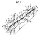
- Figure 1 is an upper right-hand perspective view of part of a roofing batten; and,
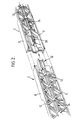
- Figure 2 is an underside perspective view of the interlocking end portions of two adjacent roofing battens.
- Conventional tiling techniques have utilised wooden battens, to which tiles of concrete, clay or other materials have been fixed using nails or clips or a combination thereof. Such costly exercises are overcome by the present invention which provides a
roofing batten 2 formed as a unitary moulding of plastics material, i.e. polyethylene, and comprising, integrally formed therewith, tile fixing means 4, see Figure 1. - The
batten 2 is wedge-shaped in cross-section, see the left-hand of Figure 1 in order to achieve accurate tile fitment in use, thebatten 2 comprising arear wall 6 and afront wall 8 spanned by anupper wall 10, see Figure 1. Reinforcingribs 12 are provided in the underside of thewall 10 between thewalls - The
upper wall 10 is provided with a centrally disposedprotuberance 14 extending therealong which is frustroconical in cross-section and together with thewalls forward channels - The
protuberance 14 is provided with gappedportions 19 along its length, see Figure 1, also for a purpose to be made clear hereinafter. - The tile fixing means 4 comprises a first snap-fit device provided by
latch elements wall 6, with avertical arm 24 of theelements horizontal arm 26 thereof extending to partially overlie thechannel 16, see Figure 1. - The tile fixing means also comprises a second snap-fit device provided by a
hook element 30 also provided on the upper extremities of thewall 6, see Figure 1. - It will be obvious that the
battens 2 which are supplied in one metre lengths and are coupled together by the conventional coupling means indicated at 32 and 33 in Figure 2, provide support for series of first and second snap-fit devices by which tiles may be secured to a roof. - In a method of tiling a roof using the
novel battens 2 of the present invention a roofer: - a) secures a plurality of
battens 2 in parallel rows to a roof structure by driving nails, not shown, into the structure throughapertures 34 provided along the length of said battens with lengthwise adjacent battens in one row being coupled together by the coupling means 32 and 33, - b) positions a first row of tiles overlying a first row of
battens 2 on the roof with their respective interlocked side portions accommodated in associated gappedportions 19 of theprotuberance 14 and with their headlap portions each being retained in snap-fit engagement under thehorizontal arms 26 of theelements battens 2, for this purpose the headlap portions of the tiles are of complementary shape to that of the recessedupper surfaces 10 of the battens. - c) positions a second row of tiles overlying a second row of
battens 2 on the roof with their headlap portions each being retained in snap-fit engagement under thehorizontal arms 26 of theelements battens 2 and with the side-lock portions of each tile in snap-fit engagement with an associatedhook element 30, and, - d) repeats step c) above until the tiling of the roof is completed.
- It will be obvious from the foregoing that tiling a roof by the described method using the
novel battens 2 of this invention provides a cost effective and most advantageous improvement on known methods of tiling. Application of the method does not detract from the security of tiles on a roof since each tile is engaged by fixing means at three points.
Claims (7)
- A roofing batten (2) comprising integral tile fixing means (4) provided by a first snap-fit device (20, 22) for engagement, when in use, with a headlap portion of a roof tile, characterised in that the tile fixing means also comprises a second snap-fit device (30) for engagement, when in use, with the side-lock portion of a roof tile.
- A roofing batten according to Claim 1 wherein the first snap-fit device comprises a hold-down clip (20, 22) overlying a recess (16) formed in an upper surface, in use, of the batten, said recess being adapted to captively receive, in use, a ribbed portion formed on an underside of a headlap portion of a tile engaged thereby.
- A roofing batten according to either one of Claims 1 and 2 wherein the second snap-fit device comprises a hook element (30) extending upwardly and rearwardly of the upper surface, in use, of the batten, said hook element being adapted, in use, to latch over a grooved side-lock portion of a roof tile engaged thereby.
- A roofing batten according to any one of Claims 1 to 3 wherein the batten (2) is of wedge-shape cross-section, or substantially so, at right angles to the length thereof, the arrangement being such that, in use, the small end (8) of the wedge shape is the upper end and faces towards the ridge of a roof on which it is used.
- A roofing batten according to any one of Claims 1 to 4 formed together with the tile fixing means as a unitary moulding of plastics material.
- A roofing batten according to Claim 5 wherein the plastics material is polyethylene.
- A method of tiling a roof comprising the steps of:a) securing a plurality of roofing battens (2) to a roof structure said battens comprising integral tile fixing means (4) provided by:i) tile retaining means (20, 22) for engagement, in use, with headlap portions of associated tiles, andii) hooks for engagement (30), in use, one each with side-lock portions of associated tiles,b) successively positioning tiles of a first row of such tiles on the roof with the headlap portions of each tile being retained in snap-fit engagement with associated tile retaining means (20, 22),c) successively positioning tiles of a second row of such tiles on the roof in overlapping relationship with the tiles of said first row with the headlap portions of each tile being retained in snap-fit engagement with associated tile retaining means (20, 22) and the side-lock portions of each tile being engaged by associated hooks (30), and,d) repeating step c) above until the tiling of the roof is completed.
Applications Claiming Priority (3)
| Application Number | Priority Date | Filing Date | Title |
|---|---|---|---|
| GB9217269 | 1992-08-14 | ||
| GB929217269A GB9217269D0 (en) | 1992-08-14 | 1992-08-14 | Roofing battens |
| PCT/EP1993/002142 WO1994004777A1 (en) | 1992-08-14 | 1993-08-10 | Roofing battens |
Publications (2)
| Publication Number | Publication Date |
|---|---|
| EP0656090A1 EP0656090A1 (en) | 1995-06-07 |
| EP0656090B1 true EP0656090B1 (en) | 1996-05-15 |
Family
ID=10720335
Family Applications (1)
| Application Number | Title | Priority Date | Filing Date |
|---|---|---|---|
| EP94908162A Expired - Lifetime EP0656090B1 (en) | 1992-08-14 | 1993-08-10 | Roofing battens |
Country Status (6)
| Country | Link |
|---|---|
| EP (1) | EP0656090B1 (en) |
| JP (1) | JPH08500160A (en) |
| AU (1) | AU675246B2 (en) |
| GB (2) | GB9217269D0 (en) |
| NZ (1) | NZ255341A (en) |
| WO (1) | WO1994004777A1 (en) |
Families Citing this family (1)
| Publication number | Priority date | Publication date | Assignee | Title |
|---|---|---|---|---|
| US5466823A (en) | 1993-11-30 | 1995-11-14 | G.D. Searle & Co. | Substituted pyrazolyl benzenesulfonamides |
Family Cites Families (8)
| Publication number | Priority date | Publication date | Assignee | Title |
|---|---|---|---|---|
| DE167719C (en) * | ||||
| FR364916A (en) * | 1906-04-04 | 1906-08-31 | Sigmund Haussen | Wind protection device for tiled roofs |
| US1463482A (en) * | 1922-12-29 | 1923-07-31 | J D Bowden | Securing shingles to roofs |
| US4141191A (en) * | 1977-05-31 | 1979-02-27 | Monier Colourtile Pty. Ltd. | Tile clip |
| AU6893487A (en) * | 1986-01-23 | 1987-08-14 | Cange Controls Ltd. | Tiling |
| US4955170A (en) * | 1987-04-29 | 1990-09-11 | Dannemann Roberto G C | Structures for roofs made of tiles or the like |
| GB2222620B (en) * | 1988-09-07 | 1992-08-26 | Richard Waddington | Roof tile securing means |
| GB2228502B (en) * | 1989-01-06 | 1992-09-02 | John Mcphee | Slate securing clip |
-
1992
- 1992-08-14 GB GB929217269A patent/GB9217269D0/en active Pending
-
1993
- 1993-08-06 GB GB9316340A patent/GB2269611B/en not_active Expired - Fee Related
- 1993-08-10 JP JP6505865A patent/JPH08500160A/en active Pending
- 1993-08-10 AU AU49472/93A patent/AU675246B2/en not_active Ceased
- 1993-08-10 WO PCT/EP1993/002142 patent/WO1994004777A1/en not_active Ceased
- 1993-08-10 NZ NZ255341A patent/NZ255341A/en unknown
- 1993-08-10 EP EP94908162A patent/EP0656090B1/en not_active Expired - Lifetime
Also Published As
| Publication number | Publication date |
|---|---|
| AU675246B2 (en) | 1997-01-30 |
| JPH08500160A (en) | 1996-01-09 |
| WO1994004777A1 (en) | 1994-03-03 |
| AU4947293A (en) | 1994-03-15 |
| GB9217269D0 (en) | 1992-09-30 |
| EP0656090A1 (en) | 1995-06-07 |
| GB2269611B (en) | 1996-01-10 |
| NZ255341A (en) | 1997-05-26 |
| GB9316340D0 (en) | 1993-09-22 |
| GB2269611A (en) | 1994-02-16 |
Similar Documents
| Publication | Publication Date | Title |
|---|---|---|
| US4914885A (en) | Roofing tile | |
| US5471807A (en) | Roofing system employing grooved batten member | |
| US4270330A (en) | Ridge batten bracket | |
| EP0733139B1 (en) | Roof tile system | |
| AU675246B2 (en) | Roofing battens | |
| IE48812B1 (en) | A ridge covering for a tiled roof | |
| EP0255533B1 (en) | Tiling | |
| AU2015249111B2 (en) | Weatherproof Roof Fixing System | |
| EP1304422A1 (en) | Ridge tile assembly | |
| JP2571930B2 (en) | Metal roof tile bar | |
| AU674531B2 (en) | Improvements in roofing | |
| JPH0699987B2 (en) | Tile block roof | |
| EP0654113B1 (en) | Tile mountings | |
| GB2354266A (en) | Eaves guard | |
| GB2314356A (en) | Method of forming a roof tile | |
| JPH09279777A (en) | Roof muntin | |
| AU752997B2 (en) | A tile, a securing and weatherproofing means and a roofing system | |
| GB2337277A (en) | Support device for use with roof valley units | |
| AU4949890A (en) | Roof valleys | |
| JPH0810113Y2 (en) | Roof tile fixing structure | |
| WO2000022256A1 (en) | A tile, a securing and weatherproofing means and a roofing system | |
| IE904267A1 (en) | Support strip | |
| WO1995003459A1 (en) | Roof structure | |
| JPH0663310B2 (en) | Horizontal roof structure | |
| JPH0715196B2 (en) | Roof attachment structure |
Legal Events
| Date | Code | Title | Description |
|---|---|---|---|
| PUAI | Public reference made under article 153(3) epc to a published international application that has entered the european phase |
Free format text: ORIGINAL CODE: 0009012 |
|
| 17P | Request for examination filed |
Effective date: 19950221 |
|
| AK | Designated contracting states |
Kind code of ref document: A1 Designated state(s): BE GB IE NL |
|
| 17Q | First examination report despatched |
Effective date: 19950811 |
|
| GRAH | Despatch of communication of intention to grant a patent |
Free format text: ORIGINAL CODE: EPIDOS IGRA |
|
| GRAA | (expected) grant |
Free format text: ORIGINAL CODE: 0009210 |
|
| AK | Designated contracting states |
Kind code of ref document: B1 Designated state(s): BE GB IE NL |
|
| REG | Reference to a national code |
Ref country code: IE Ref legal event code: FG4D Free format text: 68392 |
|
| PLBE | No opposition filed within time limit |
Free format text: ORIGINAL CODE: 0009261 |
|
| STAA | Information on the status of an ep patent application or granted ep patent |
Free format text: STATUS: NO OPPOSITION FILED WITHIN TIME LIMIT |
|
| 26N | No opposition filed | ||
| PGFP | Annual fee paid to national office [announced via postgrant information from national office to epo] |
Ref country code: IE Payment date: 19970729 Year of fee payment: 5 |
|
| PGFP | Annual fee paid to national office [announced via postgrant information from national office to epo] |
Ref country code: NL Payment date: 19970831 Year of fee payment: 5 |
|
| PGFP | Annual fee paid to national office [announced via postgrant information from national office to epo] |
Ref country code: GB Payment date: 19970918 Year of fee payment: 5 |
|
| PGFP | Annual fee paid to national office [announced via postgrant information from national office to epo] |
Ref country code: BE Payment date: 19971002 Year of fee payment: 5 |
|
| PG25 | Lapsed in a contracting state [announced via postgrant information from national office to epo] |
Ref country code: IE Free format text: LAPSE BECAUSE OF NON-PAYMENT OF DUE FEES Effective date: 19980810 Ref country code: GB Free format text: LAPSE BECAUSE OF NON-PAYMENT OF DUE FEES Effective date: 19980810 |
|
| PG25 | Lapsed in a contracting state [announced via postgrant information from national office to epo] |
Ref country code: BE Free format text: LAPSE BECAUSE OF NON-PAYMENT OF DUE FEES Effective date: 19980831 |
|
| BERE | Be: lapsed |
Owner name: REDLAND TECHNOLOGIES LTD Effective date: 19980831 |
|
| PG25 | Lapsed in a contracting state [announced via postgrant information from national office to epo] |
Ref country code: NL Free format text: LAPSE BECAUSE OF NON-PAYMENT OF DUE FEES Effective date: 19990301 |
|
| GBPC | Gb: european patent ceased through non-payment of renewal fee |
Effective date: 19980810 |
|
| NLV4 | Nl: lapsed or anulled due to non-payment of the annual fee |
Effective date: 19990301 |