EP0655956B1 - Hose coupling, ferrule therefor and methods of making the same - Google Patents
Hose coupling, ferrule therefor and methods of making the same Download PDFInfo
- Publication number
- EP0655956B1 EP0655956B1 EP93920271A EP93920271A EP0655956B1 EP 0655956 B1 EP0655956 B1 EP 0655956B1 EP 93920271 A EP93920271 A EP 93920271A EP 93920271 A EP93920271 A EP 93920271A EP 0655956 B1 EP0655956 B1 EP 0655956B1
- Authority
- EP
- European Patent Office
- Prior art keywords
- stock
- ferrule
- insert
- rotating
- hose
- Prior art date
- Legal status (The legal status is an assumption and is not a legal conclusion. Google has not performed a legal analysis and makes no representation as to the accuracy of the status listed.)
- Expired - Lifetime
Links
- 230000008878 coupling Effects 0.000 title claims abstract description 36
- 238000010168 coupling process Methods 0.000 title claims abstract description 36
- 238000005859 coupling reaction Methods 0.000 title claims abstract description 36
- 238000000034 method Methods 0.000 title claims abstract description 14
- 238000004519 manufacturing process Methods 0.000 claims abstract description 11
- 230000002093 peripheral effect Effects 0.000 claims description 23
- 239000000463 material Substances 0.000 description 5
- 238000010276 construction Methods 0.000 description 3
- 238000007493 shaping process Methods 0.000 description 3
- 239000007769 metal material Substances 0.000 description 2
- 229910001369 Brass Inorganic materials 0.000 description 1
- XAGFODPZIPBFFR-UHFFFAOYSA-N aluminium Chemical compound [Al] XAGFODPZIPBFFR-UHFFFAOYSA-N 0.000 description 1
- 229910052782 aluminium Inorganic materials 0.000 description 1
- 239000010951 brass Substances 0.000 description 1
- 238000004891 communication Methods 0.000 description 1
- 239000012530 fluid Substances 0.000 description 1
- 238000007373 indentation Methods 0.000 description 1
- 238000003780 insertion Methods 0.000 description 1
- 230000037431 insertion Effects 0.000 description 1
- 230000002787 reinforcement Effects 0.000 description 1
Images



Classifications
-
- F—MECHANICAL ENGINEERING; LIGHTING; HEATING; WEAPONS; BLASTING
- F16—ENGINEERING ELEMENTS AND UNITS; GENERAL MEASURES FOR PRODUCING AND MAINTAINING EFFECTIVE FUNCTIONING OF MACHINES OR INSTALLATIONS; THERMAL INSULATION IN GENERAL
- F16L—PIPES; JOINTS OR FITTINGS FOR PIPES; SUPPORTS FOR PIPES, CABLES OR PROTECTIVE TUBING; MEANS FOR THERMAL INSULATION IN GENERAL
- F16L33/00—Arrangements for connecting hoses to rigid members; Rigid hose-connectors, i.e. single members engaging both hoses
- F16L33/20—Undivided rings, sleeves, or like members contracted on the hose or expanded inside the hose by means of tools; Arrangements using such members
- F16L33/207—Undivided rings, sleeves, or like members contracted on the hose or expanded inside the hose by means of tools; Arrangements using such members only a sleeve being contracted on the hose
- F16L33/2071—Undivided rings, sleeves, or like members contracted on the hose or expanded inside the hose by means of tools; Arrangements using such members only a sleeve being contracted on the hose the sleeve being a separate connecting member
- F16L33/2073—Undivided rings, sleeves, or like members contracted on the hose or expanded inside the hose by means of tools; Arrangements using such members only a sleeve being contracted on the hose the sleeve being a separate connecting member directly connected to the rigid member
- F16L33/2076—Undivided rings, sleeves, or like members contracted on the hose or expanded inside the hose by means of tools; Arrangements using such members only a sleeve being contracted on the hose the sleeve being a separate connecting member directly connected to the rigid member by plastic deformation
-
- Y—GENERAL TAGGING OF NEW TECHNOLOGICAL DEVELOPMENTS; GENERAL TAGGING OF CROSS-SECTIONAL TECHNOLOGIES SPANNING OVER SEVERAL SECTIONS OF THE IPC; TECHNICAL SUBJECTS COVERED BY FORMER USPC CROSS-REFERENCE ART COLLECTIONS [XRACs] AND DIGESTS
- Y10—TECHNICAL SUBJECTS COVERED BY FORMER USPC
- Y10T—TECHNICAL SUBJECTS COVERED BY FORMER US CLASSIFICATION
- Y10T29/00—Metal working
- Y10T29/49—Method of mechanical manufacture
- Y10T29/49789—Obtaining plural product pieces from unitary workpiece
- Y10T29/49798—Dividing sequentially from leading end, e.g., by cutting or breaking
Definitions
- This invention relates to methods of making a hose coupling and a ferrule.
- a hose coupling that comprises a ferrule having opposed ends and an insert interconnected to one of the ends of the ferrule so that an end of a hose can be inserted into the other of the ends of the ferrule and over the insert to be subsequently clamped between the ferrule and the insert the ferrule being formed by radially inwardly deforming a tubular member, as illustrated in US-A-4 653 779, which document is considered to be the closest prior art.
- the prior known method of making such a ferrule from tubular stock required the making of dies that radially inwardly compress a tubular member therebetween in order to form the ferrule from the tubular member whereby a different set of dies was required for each ferrule that had a different diameter.
- ferrules can be uniquely formed from such rotating stock.
- Another object of this invention is to provide a new method of making a ferrule for a hose coupling.
- the hose coupling 30 and comprises a ferrule 31 formed of any suitable material, such as metallic material, and an insert 32 interconnected thereto in a manner hereinafter set forth, the insert 32 also being formed of any suitable material, such as metallic material.
- the ferrule 31 has opposed ends 33 and 34 as well as an external peripheral surface means 35 and an internal peripheral surface means 36, the end 33 of the ferrule 31 being radially inwardly swedged at 37 and defining a radially inwardly extending annular flange 38 that is subsequently deformed into an annular groove 39 formed in the insert 32 between an annular flange 40 on a spindle 41 thereof and an enlarged hex-shaped nut portion 42.
- the annular flange 38 can be deformed into the annular groove 39 of the insert 32 in the manner illustrated in FIGS.
- the insert 32 has an enlarged externally threaded end 45 for coupling to a coupling nut means (not shown) in a manner well known in the art, while the stem 41 of the insert 32 has a plurality of annular grooves 46 formed therein intermediate the flange 40 and a tapering end 47 of the stem 41 that facilitates the insertion of the end 47 of the insert 32 into an end of a flexible hose construction, such as an end 48 of a hose construction 49 of FIGS. 20 and 21, wherein the hose 49 is formed mainly of polymeric material and can have several layers of such polymeric material as well as reinforcement layers as desired, whereby the hose 49 is merely schematically illustrated in FIGS. 20 and 21.
- the ferrule 31 has a generally cylindrical body portion 50 thereof provided with a plurality of radially inwardly disposed annular projections 51 formed in the internal peripheral surface 36 thereof which will dig into an external peripheral surface 52 of the end 48 of the hose 49 when the ferrule 31 is radially inwardly deformed or crimped toward the insert 32 as illustrated in FIG. 21 by suitable apparatus (not shown) in a manner well known in the art. For example, see the U. S. -A- 4, 625, 539.
- the ferrule 31 is made from a length of tubular metallic stock 54 that has opposed ends, only the end 55 being illustrated in FIG. 3, and having a substantially smooth outer peripheral surface 56 and a substantially smooth internal peripheral surface 57, the stock 54 being adapted to have the non-shown end thereof fixed in a rotatable chuck 58 that is adapted to be rotated to rotate the stock 54 about the longitudinal axis thereof at any suitable speed.
- Two or more swedging rollers 59 that are respectively mounted on rotatable shafts 60 have forming peripheral surfaces 61 that are adapted to be urged toward the rotating stock 54 as indicated by the arrows 62 in FIG.
- a suitable rotatable cutting means 65 (FIG. 5) is inserted into the end 55 of the stock 54 and the stock can also be rotated by the chuck 58 or the chuck 58 can be stationary and only the cutting means 65 needs to be rotating.
- the cutting means 65 forms or cuts the internal peripheral surface 57 of the portion 66 of the stock 54 that is located between the end 55 and the deformed section 63 thereof to form the plurality of inwardly directed projections 51 for the resulting ferrule 31 in the configurations previously described.
- a suitable shaping tool 67 can be utilized to shape or finish the external peripheral surface 56 of the portion 66 by moving the same back and forth in the directions of the arrows 68 in FIG. 6 while the chuck 58 is rotating the stock 54 so as to provide a smooth external peripheral surface 35 for the resulting ferrule 31.
- a suitable cutter 69 is moved in the direction of the arrow 70 while the chuck 58 is rotating the stock 54 so as to cut the resulting portion 66 from the stock 54 to define the ferrule 31 as illustrated in FIG. 8 which can then be joined with the insert 32 in the manner illustrated in FIGS. 9-12 and previously described.
- the cutter 69 can also be utilized to thereafter cut the stock 54 to remove the remaining part 71 of the stock 54 to produce a new end 55 therefor so as to permit another ferrule 31 to be formed from the remaining stock 54 in the manner previously described.
- the insert 32 itself can be utilized as the mandrel in a unique manner.
- hose coupling is generally indicated by the reference numeral 30A and parts thereof similar to the parts of the hose construction 30 previously described are indicated by like reference numerals followed by the reference letter "A".
- the hose coupling 30A comprises the ferrule 31A and the insert 32A.
- the ferrule 31A for the hose coupling 30A is formed from the tubular stock 54A that has the non-illustrated end thereof inserted in the rotatable chuck 58A so that the end 55A is remote from the chuck 58A.
- a portion 66A of the stock 54A is initially cut into by the cutting tool 65A that has been inserted in the end 55A of the stock 54A by having the tool 65A itself rotating or just the chuck 58A rotating or a combination of the stock 54A and the tool 65A both rotating.
- the internal peripheral surface means 57A is formed by the cutting tool 65A to provide the inwardly directed projections 51A, as well as the flange 38A if desired, in a manner previously described with the projections 51A being disposed inwardly from the end 55A a distance represented by the reference numeral 72 in FIG. 14.
- an insert 32A is inserted into the end 55A of the stock 54A in the manner illustrated in FIG. 15 so that the surface 73 of the nut portion 42A of the insert 32A is adjacent the end 55A of the stock 54A.
- the shaping rollers 59A on their shafts 60A but having been turned in the opposite direction from the rollers 59 of FIGS. 3 and 4, are moved radially inwardly while the stock 54A is being rotated by the rotating chuck 58A in the manner illustrated in FIGS. 15 and 16 to deform the stock 54A into the portion 63A thereof that forms the part 37A of the ferrule 31A.
- rollers 59A are moved radially inwardly in the direction of the arrows 62A a distance sufficient to cause the part 63A to form the flange 38A into the annular groove 39A of the insert 32A as illustrated in FIG. 16 so as to interconnect the section 63A of the stock 54A directly to the insert 32A as illustrated.
- the shaping tool 67A can be utilized to shape the external peripheral surface 56A of the stock 54A, such as by moving the tool 67A back and forth as represented by the arrows 68A.
- the stock 54A is then cut off by the cutting tool 69A at the proper location to form the completed ferrule 31A as well as the completed hose coupling 30A as illustrated in FIG. 18.
- FIGS. 13-18 produces the hose coupling 30A without requiring the stock 54A to utilize a separate mandrel 64 therewith when utilizing the rollers 59A so that the method of FIGS. 13-18 forms the hose coupling 30A when the portion 66A of the stock 54A is cut therefrom by the cutting tool 69A as previously described, the cutting tool 69A thereby forming a new end 55A on the stock 54A so as to permit another hose coupling 30A to be formed from the stock 54A in the manner previously set forth.
- ferrule 31 or 31A and the insert 32 or 32A therefor can have any suitable dimensions and can be formed of any suitable material, the following dimensions are given for one working embodiment of the hose coupling 30 or 30A of this invention with the understanding that the same is not to be a limitation on this invention.
- one working embodiment of this invention has the ferrule 31 or 31A formed of aluminum 6061 T6 wherein the inside diameter thereof is approximately 2.057 cm (0.810 of an inch) or 2.083 cm (0.820 of an inch), the outer diameter thereof is approximately 2.662 cm (1.048 inches) or 2.687 cm (1.058 inches) and the length between the ends 33 or 33A and 34 or 34A thereof is approximately 3.035 cm (1.195 inches) or 3.061 cm (1.205 inches).
- the insert 32 or 32A is formed of brass and is approximately 5.936 cm (2.337 inches) long with the annular groove 39 or 39A being defined by a diameter of approximately 1.247 cm (0.491 of an inch) or 1.273 cm (0.501 of an inch) while the diameter of the flange 40 or 40A is approximately 1.496 cm (0.589 of an inch) or 1.521 cm (0.599 of an inch).
- this invention provides a new method of making a ferrule for a hose coupling and a new method of making a hose coupling utilizing such a ferrule.
Landscapes
- Engineering & Computer Science (AREA)
- General Engineering & Computer Science (AREA)
- Mechanical Engineering (AREA)
- Joints That Cut Off Fluids, And Hose Joints (AREA)
- Shaping Of Tube Ends By Bending Or Straightening (AREA)
- Mechanical Coupling Of Light Guides (AREA)
- Food-Manufacturing Devices (AREA)
Abstract
Description
- This invention relates to methods of making a hose coupling and a ferrule.
- It is known to make a hose coupling that comprises a ferrule having opposed ends and an insert interconnected to one of the ends of the ferrule so that an end of a hose can be inserted into the other of the ends of the ferrule and over the insert to be subsequently clamped between the ferrule and the insert the ferrule being formed by radially inwardly deforming a tubular member, as illustrated in US-A-4 653 779, which document is considered to be the closest prior art.
- It is one of the features of this invention to provide a new method of making a ferrule for a hose coupling wherein the ferrule can be made from tubular stock in a simple and effective manner.
- In particular, the prior known method of making such a ferrule from tubular stock required the making of dies that radially inwardly compress a tubular member therebetween in order to form the ferrule from the tubular member whereby a different set of dies was required for each ferrule that had a different diameter.
- However, it was found according to the teachings of this invention that by merely rotating a length of tubular stock and while the stock is rotating, radially inwardly swedging a part thereof in a desired location in a simple and effective manner, ferrules can be uniquely formed from such rotating stock.
- Accordingly, it is an object of this invention to provide a new method of making a hose coupling.
- Another object of this invention is to provide a new method of making a ferrule for a hose coupling.
- These objects are realised by the subject-matter of the appended claims.
- The features of the invention, and its technical advantages, can be seen from the following description of the preferred embodiments, together with the claims and the accompanying drawings, in which:
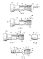
- FIG. 1 is a perspective view of a hose coupling ;
- FIG. 2 is a rear perspective view of the hose coupling of FIG. 1;
- FIG. 3 is a schematic view illustrating one of the steps of the method of making the hose coupling of FIG. 1;
- FIG. 4 is a view similar to FIG. 3 and illustrates another step in the method wherein rotating tubular stock is radially inwardly swedged;
- FIG. 5 is a view similar to FIG. 4 and illustrates how the swedged stock of FIG. 4 is internally cut;
- FIG. 6 is a view similar to FIG. 5 and illustrates another step for finishing the outer peripheral surface of a portion of the swedged tubular stock;
- FIG. 7 is a view similar to FIG. 6 and illustrates how a portion of the swedged tubular stock is cut from the remainder of the stock;
- FIG. 8 is a side view of the ferrule cut from the stock of FIG. 7;
- FIG. 9 is an exploded view illustrating the ferrule of FIG. 8 in axial cross-section before the same is assembled to an insert;
- FIG. 10 illustrates the ferrule and insert of FIG. 9 in their assembled condition;
- FIG. 11 illustrates how the ferrule of FIG. 10 is subsequently deformed to interconnect with the insert of FIG. 10;
- FIG. 12 is a side view in elevation of the completed hose coupling of FIG. 11;
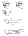
- FIG. 13 is a view similar to FIG. 3 and illustrates one step in another method;
- FIG. 14 is a view similar to FIG. 13 and illustrates how a portion of the rotating tubular stock has the internal peripheral surface thereof cut into;
- FIG. 15 is a view similar to FIG. 14 and illustrates how an insert of a hose coupling is disposed in the stock of FIG. 14 before the same is radially inwardly swedged;
- FIG. 16 is a view similar to FIG. 15 and illustrates how the rotating stock of FIG. 15 is radially inwardly swedged to not only form a swedged portion of the tubular stock but also to interconnect the swedged portion of the ferrule to the insert that has been inserted therein;
- FIG. 17 is a view similar to FIG. 16 and illustrates how the outer peripheral surface of a portion of the tubular stock is shaped;
- FIG. 18 is a view similar to FIG. 17 and illustrates how the formed portion of the tubular stock is cut therefrom;
- FIG. 19 is a side view of the completed hose coupling that has been cut from the tubular stock of FIG. 18;
- FIG. 20 is a cross-sectional view illustrating how one of the hose couplings receives an end of a hose therein; and
- FIG. 21 is a view similar to FIG. 20 and illustrates how the ferrule of the hose coupling is radially inwardly deformed or crimped to clamp the end of the hose thereto.
-
- Referring now to FIGS. 1 and 2, the
hose coupling 30 and comprises aferrule 31 formed of any suitable material, such as metallic material, and aninsert 32 interconnected thereto in a manner hereinafter set forth, theinsert 32 also being formed of any suitable material, such as metallic material. - As illustrated in FIG. 9, the
ferrule 31 has opposedends end 33 of theferrule 31 being radially inwardly swedged at 37 and defining a radially inwardly extendingannular flange 38 that is subsequently deformed into anannular groove 39 formed in theinsert 32 between anannular flange 40 on aspindle 41 thereof and an enlarged hex-shaped nut portion 42. For example, theannular flange 38 can be deformed into theannular groove 39 of theinsert 32 in the manner illustrated in FIGS. 10-12 wherein deforming diemembers 43 are moved against the externalperipheral surface 35 of theferrule 31 at theend 33 thereof to force theannular flange 38 into theannular groove 39 as illustrated in FIG. 11, all in a manner well known in the art, whereby the dies form theindentations 44 in the externalperipheral surface 35 of theferrule 31 in the manner illustrated in FIG. 12. - The
insert 32 has an enlarged externally threadedend 45 for coupling to a coupling nut means (not shown) in a manner well known in the art, while thestem 41 of theinsert 32 has a plurality ofannular grooves 46 formed therein intermediate theflange 40 and atapering end 47 of thestem 41 that facilitates the insertion of theend 47 of theinsert 32 into an end of a flexible hose construction, such as anend 48 of ahose construction 49 of FIGS. 20 and 21, wherein thehose 49 is formed mainly of polymeric material and can have several layers of such polymeric material as well as reinforcement layers as desired, whereby thehose 49 is merely schematically illustrated in FIGS. 20 and 21. - The
ferrule 31 has a generallycylindrical body portion 50 thereof provided with a plurality of radially inwardly disposedannular projections 51 formed in the internalperipheral surface 36 thereof which will dig into an externalperipheral surface 52 of theend 48 of thehose 49 when theferrule 31 is radially inwardly deformed or crimped toward theinsert 32 as illustrated in FIG. 21 by suitable apparatus (not shown) in a manner well known in the art. For example, see the U. S. -A- 4, 625, 539. - Such inward collapsing of the
ferrule 31 toward theinsert 32 causes an internalperipheral surface 53 of theend 48 of thehose 49 to be compressed into theannular grooves 46 of theinsert 32 whereby it can be seen that theend 48 of thehose 49 is securely fastened in thehose coupling 30 of this invention in a manner well known in the art, with the flow passage in thehose 49 being in fluid communication with the flow passage of the insert that passes completely therethrough in a manner well known in the art. For example, see the aforementioned U. S. -A- 4, 625, 539. - While the general structure and operation of the
hose coupling 30 is well known in the art, the method of making thehose coupling 30 of this invention is unique and will now be described. - The
ferrule 31 is made from a length of tubularmetallic stock 54 that has opposed ends, only theend 55 being illustrated in FIG. 3, and having a substantially smooth outerperipheral surface 56 and a substantially smooth internalperipheral surface 57, thestock 54 being adapted to have the non-shown end thereof fixed in arotatable chuck 58 that is adapted to be rotated to rotate thestock 54 about the longitudinal axis thereof at any suitable speed. Two or more swedgingrollers 59 that are respectively mounted onrotatable shafts 60 have formingperipheral surfaces 61 that are adapted to be urged toward the rotatingstock 54 as indicated by thearrows 62 in FIG. 4 to inwardly shape asection 63 of thestock 54 intermediate the opposed ends thereof at a predetermined location relative to theend 55 thereof as illustrated in FIG. 4, a cylindricalmetallic mandrel 64 having been first initially inserted in theend 55 of thestock 54 so as to cooperate with therollers 59 to define the nowdeformed section 63 which is in thefinal shape 37 for the resultingferrule 31 as will be apparent hereinafter. - After the
rollers 59 have been retracted from thestock 54 and themandrel 64 has been removed out of theend 55 of thestock 54, a suitable rotatable cutting means 65 (FIG. 5) is inserted into theend 55 of thestock 54 and the stock can also be rotated by thechuck 58 or thechuck 58 can be stationary and only thecutting means 65 needs to be rotating. - In any event, the cutting means 65 forms or cuts the internal
peripheral surface 57 of theportion 66 of thestock 54 that is located between theend 55 and thedeformed section 63 thereof to form the plurality of inwardly directedprojections 51 for the resultingferrule 31 in the configurations previously described. - Thereafter the
cutting means 65 is removed from thestock 54 and asuitable shaping tool 67 can be utilized to shape or finish the externalperipheral surface 56 of theportion 66 by moving the same back and forth in the directions of thearrows 68 in FIG. 6 while thechuck 58 is rotating thestock 54 so as to provide a smooth externalperipheral surface 35 for the resultingferrule 31. - As illustrated in FIG. 7, after the forming
tool 67 has been utilized, asuitable cutter 69 is moved in the direction of thearrow 70 while thechuck 58 is rotating thestock 54 so as to cut the resultingportion 66 from thestock 54 to define theferrule 31 as illustrated in FIG. 8 which can then be joined with theinsert 32 in the manner illustrated in FIGS. 9-12 and previously described. - The
cutter 69 can also be utilized to thereafter cut thestock 54 to remove theremaining part 71 of thestock 54 to produce anew end 55 therefor so as to permit anotherferrule 31 to be formed from theremaining stock 54 in the manner previously described. - Instead of utilizing the
mandrel 64 to cooperate with therollers 59 in forming theportion 63 of thestock 54 as previously described, theinsert 32 itself can be utilized as the mandrel in a unique manner. - For example, another hose coupling is generally indicated by the
reference numeral 30A and parts thereof similar to the parts of thehose construction 30 previously described are indicated by like reference numerals followed by the reference letter "A". - As illustrated in FIG. 19, the
hose coupling 30A comprises theferrule 31A and theinsert 32A. - The
ferrule 31A for thehose coupling 30A is formed from thetubular stock 54A that has the non-illustrated end thereof inserted in therotatable chuck 58A so that theend 55A is remote from thechuck 58A. - A
portion 66A of thestock 54A is initially cut into by thecutting tool 65A that has been inserted in theend 55A of thestock 54A by having thetool 65A itself rotating or just thechuck 58A rotating or a combination of thestock 54A and thetool 65A both rotating. In any event, the internal peripheral surface means 57A is formed by thecutting tool 65A to provide the inwardly directed projections 51A, as well as theflange 38A if desired, in a manner previously described with the projections 51A being disposed inwardly from theend 55A a distance represented by thereference numeral 72 in FIG. 14. - Thereafter, an
insert 32A is inserted into theend 55A of thestock 54A in the manner illustrated in FIG. 15 so that thesurface 73 of thenut portion 42A of theinsert 32A is adjacent theend 55A of thestock 54A. Thereafter, theshaping rollers 59A on theirshafts 60A, but having been turned in the opposite direction from therollers 59 of FIGS. 3 and 4, are moved radially inwardly while thestock 54A is being rotated by the rotatingchuck 58A in the manner illustrated in FIGS. 15 and 16 to deform thestock 54A into theportion 63A thereof that forms thepart 37A of theferrule 31A. In addition, therollers 59A are moved radially inwardly in the direction of thearrows 62A a distance sufficient to cause thepart 63A to form theflange 38A into theannular groove 39A of theinsert 32A as illustrated in FIG. 16 so as to interconnect thesection 63A of thestock 54A directly to theinsert 32A as illustrated. - Thereafter, as illustrated in FIG. 17, the
shaping tool 67A can be utilized to shape the external peripheral surface 56A of thestock 54A, such as by moving thetool 67A back and forth as represented by thearrows 68A. - The
stock 54A is then cut off by thecutting tool 69A at the proper location to form the completedferrule 31A as well as the completedhose coupling 30A as illustrated in FIG. 18. - Therefore, it can be seen that the method illustrated in FIGS. 13-18 produces the
hose coupling 30A without requiring thestock 54A to utilize aseparate mandrel 64 therewith when utilizing therollers 59A so that the method of FIGS. 13-18 forms thehose coupling 30A when theportion 66A of thestock 54A is cut therefrom by thecutting tool 69A as previously described, thecutting tool 69A thereby forming anew end 55A on thestock 54A so as to permit anotherhose coupling 30A to be formed from thestock 54A in the manner previously set forth. - While the
ferrule insert hose coupling - In particular, one working embodiment of this invention has the
ferrule ends insert annular groove flange 40 or 40A is approximately 1.496 cm (0.589 of an inch) or 1.521 cm (0.599 of an inch). - Therefore, it can be seen that this invention provides a new method of making a ferrule for a hose coupling and a new method of making a hose coupling utilizing such a ferrule.
Claims (8)
- A method of making a ferrule (31, 31A) for a hose coupling (30, 30A) that comprises said ferrule having opposed ends (33, 34) and an insert (32, 32A) interconnected to one of said ends of said ferrule (31, 31A) so that an end (48) of a hose (49) can be inserted into the other of said ends of said ferrule (31, 31A) and over said insert (32, 32A) to be subsequently clamped between said ferrule and said insert, characterized by the steps of forming said ferrule (31, 31A) from a length of tubular stock (54, 54A) that has opposed ends by rotating said stock, inwardly swedging said stock (54, 54A) at a predetermined location (37, 37A) thereof that is spaced inwardly from one end (55, 55A) of said stock (54, 54A) to define said one end of said ferrule (31, 31A) while said stock is rotating, then forming the internal peripheral surface (36) of said ferrule (31, 31A) to have a plurality of radially inwardly directed annular projections (51, 51A), and then cutting off a portion (66, 66A) of said stock (54, 54A) at a desired location thereon that is spaced inwardly from said one end (55, 55A) of said stock (54, 54A) to form said ferrule (31, 31A) so as to permit said stock to have another ferrule formed therefrom in the same manner.
- A method of making a hose coupling (30, 30A) that comprises a ferrule (31, 31A) having opposed ends (33, 34) and an insert (32, 32A) interconnected to one of said ends of said ferrule (31, 31A) so that an end (48) of a hose (49) can be inserted into the other of said ends of said ferrule (31, 31A) and over said insert (32, 32A) to be subsequently clamped between said ferrule and said insert, characterized by the steps of forming said ferrule (31, 31A) from a length of tubular stock (54, 54A) that has opposed ends by rotating said stock, inserting part of said insert (32A) into one of said opposed ends (55, 55A) of said tubular stock (54, 54A), inwardly swedging said stock (54, 54A) at said one of said opposed ends (55, 55A) thereof to define said one end of said ferrule (31, 31A) while said stock is rotating and to interconnect said one end of said ferrule (31, 31A) to said part of said insert (32A), and then cutting off a portion (66, 66A) of said stock (54, 54A) at a desired location thereon that is spaced inwardly from said one end (55, 55A) of said stock (54, 54A) to form said other end of said ferrule (31, 31A) and to complete said coupling (30, 30A) while said desired location on said stock (54, 54A) becomes a new one end thereof for forming another coupling (30, 30A) in the above manner.
- A method as set forth in claim 2 and characterized by the step of forming the internal peripheral surface (36) of said ferrule (31, 31A) to have a plurality of radially inwardly directed annular projections (51, 51A).
- A method as set forth in claim 1 or 3 wherein the step of forming said internal peripheral surface (36) is characterized by the step of cutting into said internal peripheral surface.
- A method as set forth in claim 1 wherein said predetermined location (37) on said stock (54) and said desired location on said stock are substantially the same location on said stock.
- A method as set forth in claim 3 wherein the step of forming said internal peripheral surface takes place while said stock (54A) is rotating and before the step of inserting said part of said insert (32A) into said one of said opposed ends of said stock (54A).
- A method as set forth in claim 1 wherein the step of swedging said stock (54, 54A) is characterized by the steps of rotating said stock, and urging swedging roller means (59, 59A) radially inwardly against said rotating stock (54, 54A) to swedge said stock.
- A method as set forth in claim 2 wherein the step of swedging said stock (54, 54A) is characterized by the step of urging swedging roller means (59, 59A) radially inwardly against said rotating stock (54, 54A) to swedge said stock against said part of said insert (32A).
Applications Claiming Priority (3)
| Application Number | Priority Date | Filing Date | Title |
|---|---|---|---|
| US934048 | 1992-08-21 | ||
| US07/934,048 US5285561A (en) | 1992-08-21 | 1992-08-21 | Hose coupling, ferrule therefor and methods of making the same |
| PCT/US1993/007920 WO1994004294A1 (en) | 1992-08-21 | 1993-08-17 | Hose coupling, ferrule therefor and methods of making the same |
Publications (3)
| Publication Number | Publication Date |
|---|---|
| EP0655956A1 EP0655956A1 (en) | 1995-06-07 |
| EP0655956A4 EP0655956A4 (en) | 1997-01-02 |
| EP0655956B1 true EP0655956B1 (en) | 1999-12-29 |
Family
ID=25464876
Family Applications (1)
| Application Number | Title | Priority Date | Filing Date |
|---|---|---|---|
| EP93920271A Expired - Lifetime EP0655956B1 (en) | 1992-08-21 | 1993-08-17 | Hose coupling, ferrule therefor and methods of making the same |
Country Status (8)
| Country | Link |
|---|---|
| US (3) | US5285561A (en) |
| EP (1) | EP0655956B1 (en) |
| AU (1) | AU672440B2 (en) |
| CA (1) | CA2140644C (en) |
| DE (1) | DE69327466T2 (en) |
| ES (1) | ES2140466T3 (en) |
| MX (1) | MX9305066A (en) |
| WO (1) | WO1994004294A1 (en) |
Families Citing this family (27)
| Publication number | Priority date | Publication date | Assignee | Title |
|---|---|---|---|---|
| US6691412B2 (en) * | 1999-12-30 | 2004-02-17 | Tokai Rubber Industries, Ltd. | Hose-connector assembly including outer rubber protector tube which covers entire length of inner resin tube, and method of producing the same |
| US20060265852A1 (en) * | 2001-01-19 | 2006-11-30 | Victaulic Company | Triple-expanded mechanical pipe coupling derived from a standard fitting |
| US20080185840A1 (en) | 2007-02-07 | 2008-08-07 | Eric Menor | Hex swaged fluid coupling and method of making same |
| ES2426769T3 (en) * | 2009-01-29 | 2013-10-25 | Eaton Industrial IP GmbH & Co. KG | Hose fitting and method for attaching the hose fitting to a hose |
| US8888141B2 (en) * | 2009-10-30 | 2014-11-18 | Caterpillar Inc. | Fluid coupling assembly and method of manufacture |
| US8356506B2 (en) * | 2011-02-25 | 2013-01-22 | Szuba Consulting, Inc. | Method of forming industrial housings |
| US9021701B1 (en) | 2011-09-26 | 2015-05-05 | Dayco Ip Holdings, Llc | Ferrule, hose coupling, and methods of making same |
| DE102012002994A1 (en) * | 2012-02-15 | 2013-08-22 | GM Global Technology Operations LLC (n. d. Gesetzen des Staates Delaware) | Solderless hose connection for a line section of an air conditioning system |
| CN104755188B (en) * | 2012-11-12 | 2016-09-14 | 日本斯频德制造株式会社 | Plastic working method and spinning device used for the plastic working method |
| US10458574B2 (en) | 2015-04-24 | 2019-10-29 | Teknor Apex Company | Lightweight, high flow hose assembly and method of manufacture |
| USD779640S1 (en) | 2015-04-24 | 2017-02-21 | Teknor Apex Company | Female hose fitting |
| US10000035B2 (en) | 2015-04-24 | 2018-06-19 | Teknor Apex Company | Lightweight, high flow hose assembly and method of manufacture |
| USD757233S1 (en) * | 2015-04-24 | 2016-05-24 | Teknor Apex Company | Male hose fitting |
| US10132435B2 (en) | 2015-04-24 | 2018-11-20 | Teknor Apex Company | Lightweight, high flow hose assembly and method of manufacture |
| US9815254B2 (en) | 2015-04-24 | 2017-11-14 | Teknor Apex Company | Lightweight, high flow hose assembly and method of manufacture |
| US9810357B2 (en) | 2015-04-24 | 2017-11-07 | Teknor Apex Company | Lightweight, high flow hose assembly and method of manufacture |
| USD782623S1 (en) | 2015-09-01 | 2017-03-28 | Teknor Apex Company | Female hose fitting |
| USD777888S1 (en) | 2015-09-01 | 2017-01-31 | Teknor Apex Company | Male hose fitting |
| USD812202S1 (en) | 2015-10-29 | 2018-03-06 | Teknor Apex Company | Radially expandable hose assembly including fittings |
| USD806838S1 (en) | 2015-10-29 | 2018-01-02 | Teknor Apex Company | Radially expandable hose assembly |
| USD784497S1 (en) | 2016-04-15 | 2017-04-18 | Teknor Apec Company | Male hose fitting |
| USD785141S1 (en) | 2016-04-15 | 2017-04-25 | Teknor Apex Company | Female hose fitting |
| US10458576B2 (en) | 2016-10-13 | 2019-10-29 | Teknor Apex Company | Hose assembly with modified thermoplastic inner tube |
| DE102017103156A1 (en) * | 2017-02-16 | 2018-08-16 | Ka Group Ag | Crimp coupling for connecting a hose with a pipe nipple |
| JP7106991B2 (en) * | 2018-05-31 | 2022-07-27 | 日本製鉄株式会社 | Roll, welding equipment using the same, and steel plate manufacturing method |
| US11583915B2 (en) | 2019-04-26 | 2023-02-21 | Steris Instrument Management Services, Inc. | Hose crimping assembly |
| USD921853S1 (en) | 2019-10-22 | 2021-06-08 | Teknor Apex Company | Male hose fitting |
Family Cites Families (8)
| Publication number | Priority date | Publication date | Assignee | Title |
|---|---|---|---|---|
| US3299680A (en) * | 1965-06-10 | 1967-01-24 | Earl A Thompson | Rolling machine for forming tubular workpieces |
| US3653240A (en) * | 1969-02-28 | 1972-04-04 | Charles K Huthsing Jr | Apparatus for manufacture of tubular projectiles |
| US3688717A (en) * | 1970-09-14 | 1972-09-05 | Nathan H Rudolph | Dial feed die arrangement for forming compression fittings |
| US4064614A (en) * | 1976-12-23 | 1977-12-27 | Samuel Moore And Company | Method of making an improved hose and tube coupling |
| US4162569A (en) * | 1977-10-17 | 1979-07-31 | Dana Corporation | Method of making metal gaskets |
| US4305608A (en) * | 1979-07-13 | 1981-12-15 | The Gates Rubber Company | Ferrule, coupling and process |
| DE3432443C2 (en) * | 1984-09-04 | 1986-08-14 | Klaus Ing.(grad.) 4232 Xanten Dietzel | Process for producing a hose compression sleeve for high pressure application and apparatus for carrying out this process |
| US4653779A (en) * | 1986-03-17 | 1987-03-31 | Dayco Products, Inc. | Hose coupling and method of making the same |
-
1992
- 1992-08-21 US US07/934,048 patent/US5285561A/en not_active Expired - Lifetime
-
1993
- 1993-08-17 DE DE69327466T patent/DE69327466T2/en not_active Expired - Lifetime
- 1993-08-17 WO PCT/US1993/007920 patent/WO1994004294A1/en not_active Ceased
- 1993-08-17 ES ES93920271T patent/ES2140466T3/en not_active Expired - Lifetime
- 1993-08-17 CA CA002140644A patent/CA2140644C/en not_active Expired - Lifetime
- 1993-08-17 EP EP93920271A patent/EP0655956B1/en not_active Expired - Lifetime
- 1993-08-17 AU AU50874/93A patent/AU672440B2/en not_active Expired
- 1993-08-20 MX MX9305066A patent/MX9305066A/en unknown
- 1993-10-27 US US08/144,086 patent/US5339668A/en not_active Expired - Lifetime
-
1994
- 1994-04-04 US US08/222,217 patent/US5419028A/en not_active Expired - Lifetime
Also Published As
| Publication number | Publication date |
|---|---|
| EP0655956A1 (en) | 1995-06-07 |
| EP0655956A4 (en) | 1997-01-02 |
| CA2140644A1 (en) | 1994-03-03 |
| MX9305066A (en) | 1994-04-29 |
| US5339668A (en) | 1994-08-23 |
| CA2140644C (en) | 2006-11-07 |
| WO1994004294A1 (en) | 1994-03-03 |
| ES2140466T3 (en) | 2000-03-01 |
| AU672440B2 (en) | 1996-10-03 |
| AU5087493A (en) | 1994-03-15 |
| US5285561A (en) | 1994-02-15 |
| DE69327466D1 (en) | 2000-02-03 |
| US5419028A (en) | 1995-05-30 |
| DE69327466T2 (en) | 2000-06-15 |
Similar Documents
| Publication | Publication Date | Title |
|---|---|---|
| AU672440B2 (en) | Hose coupling, ferrule therefor and methods of making the same | |
| EP2356364B1 (en) | Crimpable or swageable fluid power ferrules, couplings, systems and methods | |
| US5370425A (en) | Tube-to-hose coupling (spin-sert) and method of making same | |
| CA2103928C (en) | Torque transmitting structure and method of manufacture | |
| SE509808C2 (en) | Ways to attach a hose to a nipple and a hose connection thus obtained | |
| CA2050779A1 (en) | Pressure hose coupling collar and method for producing same | |
| US4381594A (en) | Method of cold forming coupling shell | |
| US3838592A (en) | Hose end fittings and inserts therefor | |
| CA1057790A (en) | Air hose fitting and method of making same | |
| US5881592A (en) | Floating plug for drawing of tubes | |
| EP0640414A1 (en) | Method of manufacturing a hollow steering shaft and hollow steering shaft | |
| JP3738402B2 (en) | Pipe connecting end forming apparatus and pipe connecting end forming method | |
| EP0003142A2 (en) | Hose fitting and method of assembly | |
| US4173876A (en) | Method of producing metal tubing | |
| US20050200227A1 (en) | Method for manufacturing motor yoke, motor yoke, and motor | |
| US6186559B1 (en) | Tube coupling assembly | |
| CN1430007A (en) | Hose connector for tubular member and its applied method | |
| US4829654A (en) | Method of manufacturing a pressurized fluid coupling | |
| US5129251A (en) | Manufacturing process for end fitting for eye joint | |
| JPH079066A (en) | Extrusion molding equipment | |
| JPH0839178A (en) | Method for manufacturing tubular product having window hole in intermediate bulge | |
| JP3014491B2 (en) | Method of manufacturing eye joint by cold rolling | |
| US20040139775A1 (en) | Method of forming double O-ring | |
| EP0428355A2 (en) | Method and apparatus for forming ducting | |
| US20020069507A1 (en) | Method of producing a one-piece stamped socket for hydraulic hose fittings |
Legal Events
| Date | Code | Title | Description |
|---|---|---|---|
| PUAI | Public reference made under article 153(3) epc to a published international application that has entered the european phase |
Free format text: ORIGINAL CODE: 0009012 |
|
| 17P | Request for examination filed |
Effective date: 19950201 |
|
| AK | Designated contracting states |
Kind code of ref document: A1 Designated state(s): DE ES FR GB IT SE |
|
| RHK1 | Main classification (correction) |
Ipc: F16L 33/207 |
|
| A4 | Supplementary search report drawn up and despatched |
Effective date: 19961112 |
|
| AK | Designated contracting states |
Kind code of ref document: A4 Designated state(s): DE ES FR GB IT SE |
|
| 17Q | First examination report despatched |
Effective date: 19981117 |
|
| GRAG | Despatch of communication of intention to grant |
Free format text: ORIGINAL CODE: EPIDOS AGRA |
|
| GRAG | Despatch of communication of intention to grant |
Free format text: ORIGINAL CODE: EPIDOS AGRA |
|
| GRAH | Despatch of communication of intention to grant a patent |
Free format text: ORIGINAL CODE: EPIDOS IGRA |
|
| GRAH | Despatch of communication of intention to grant a patent |
Free format text: ORIGINAL CODE: EPIDOS IGRA |
|
| GRAA | (expected) grant |
Free format text: ORIGINAL CODE: 0009210 |
|
| AK | Designated contracting states |
Kind code of ref document: B1 Designated state(s): DE ES FR GB IT SE |
|
| REF | Corresponds to: |
Ref document number: 69327466 Country of ref document: DE Date of ref document: 20000203 |
|
| REG | Reference to a national code |
Ref country code: ES Ref legal event code: FG2A Ref document number: 2140466 Country of ref document: ES Kind code of ref document: T3 |
|
| ITF | It: translation for a ep patent filed | ||
| ET | Fr: translation filed | ||
| PLBE | No opposition filed within time limit |
Free format text: ORIGINAL CODE: 0009261 |
|
| STAA | Information on the status of an ep patent application or granted ep patent |
Free format text: STATUS: NO OPPOSITION FILED WITHIN TIME LIMIT |
|
| 26N | No opposition filed | ||
| REG | Reference to a national code |
Ref country code: GB Ref legal event code: IF02 |
|
| PGFP | Annual fee paid to national office [announced via postgrant information from national office to epo] |
Ref country code: GB Payment date: 20120828 Year of fee payment: 20 Ref country code: SE Payment date: 20120829 Year of fee payment: 20 |
|
| PGFP | Annual fee paid to national office [announced via postgrant information from national office to epo] |
Ref country code: FR Payment date: 20120830 Year of fee payment: 20 Ref country code: IT Payment date: 20120823 Year of fee payment: 20 Ref country code: ES Payment date: 20120827 Year of fee payment: 20 Ref country code: DE Payment date: 20120829 Year of fee payment: 20 |
|
| REG | Reference to a national code |
Ref country code: DE Ref legal event code: R071 Ref document number: 69327466 Country of ref document: DE |
|
| REG | Reference to a national code |
Ref country code: GB Ref legal event code: PE20 Expiry date: 20130816 |
|
| REG | Reference to a national code |
Ref country code: SE Ref legal event code: EUG |
|
| PG25 | Lapsed in a contracting state [announced via postgrant information from national office to epo] |
Ref country code: DE Free format text: LAPSE BECAUSE OF EXPIRATION OF PROTECTION Effective date: 20130820 |
|
| PG25 | Lapsed in a contracting state [announced via postgrant information from national office to epo] |
Ref country code: GB Free format text: LAPSE BECAUSE OF EXPIRATION OF PROTECTION Effective date: 20130816 |
|
| REG | Reference to a national code |
Ref country code: ES Ref legal event code: FD2A Effective date: 20140925 |
|
| PG25 | Lapsed in a contracting state [announced via postgrant information from national office to epo] |
Ref country code: ES Free format text: LAPSE BECAUSE OF EXPIRATION OF PROTECTION Effective date: 20130818 |