EP0655218A1 - Physical-information detecting system - Google Patents
Physical-information detecting system Download PDFInfo
- Publication number
- EP0655218A1 EP0655218A1 EP94118518A EP94118518A EP0655218A1 EP 0655218 A1 EP0655218 A1 EP 0655218A1 EP 94118518 A EP94118518 A EP 94118518A EP 94118518 A EP94118518 A EP 94118518A EP 0655218 A1 EP0655218 A1 EP 0655218A1
- Authority
- EP
- European Patent Office
- Prior art keywords
- physical
- information
- signal
- signals
- detecting system
- Prior art date
- Legal status (The legal status is an assumption and is not a legal conclusion. Google has not performed a legal analysis and makes no representation as to the accuracy of the status listed.)
- Granted
Links
- 230000008859 change Effects 0.000 claims abstract description 26
- 230000036772 blood pressure Effects 0.000 claims description 47
- 230000010349 pulsation Effects 0.000 claims description 20
- QVGXLLKOCUKJST-UHFFFAOYSA-N atomic oxygen Chemical compound [O] QVGXLLKOCUKJST-UHFFFAOYSA-N 0.000 claims description 13
- 239000008280 blood Substances 0.000 claims description 13
- 210000004369 blood Anatomy 0.000 claims description 13
- 239000001301 oxygen Substances 0.000 claims description 13
- 229910052760 oxygen Inorganic materials 0.000 claims description 13
- STCOOQWBFONSKY-UHFFFAOYSA-N tributyl phosphate Chemical compound CCCCOP(=O)(OCCCC)OCCCC STCOOQWBFONSKY-UHFFFAOYSA-N 0.000 description 10
- 238000000034 method Methods 0.000 description 9
- 238000002565 electrocardiography Methods 0.000 description 8
- 230000006870 function Effects 0.000 description 8
- 238000001361 intraarterial administration Methods 0.000 description 6
- 230000008569 process Effects 0.000 description 6
- 239000000523 sample Substances 0.000 description 6
- 230000000007 visual effect Effects 0.000 description 5
- 238000010276 construction Methods 0.000 description 3
- CWPKTBMRVATCBL-UHFFFAOYSA-N 3-[1-[1-[(2-methylphenyl)methyl]piperidin-4-yl]piperidin-4-yl]-1h-benzimidazol-2-one Chemical compound CC1=CC=CC=C1CN1CCC(N2CCC(CC2)N2C(NC3=CC=CC=C32)=O)CC1 CWPKTBMRVATCBL-UHFFFAOYSA-N 0.000 description 2
- 230000009471 action Effects 0.000 description 2
- 210000001367 artery Anatomy 0.000 description 2
- 238000004891 communication Methods 0.000 description 2
- 230000003287 optical effect Effects 0.000 description 2
- 230000029058 respiratory gaseous exchange Effects 0.000 description 2
- CURLTUGMZLYLDI-UHFFFAOYSA-N Carbon dioxide Chemical compound O=C=O CURLTUGMZLYLDI-UHFFFAOYSA-N 0.000 description 1
- 238000004364 calculation method Methods 0.000 description 1
- 235000011089 carbon dioxide Nutrition 0.000 description 1
- 230000035487 diastolic blood pressure Effects 0.000 description 1
- 239000007789 gas Substances 0.000 description 1
- 238000012986 modification Methods 0.000 description 1
- 230000004048 modification Effects 0.000 description 1
- 230000035488 systolic blood pressure Effects 0.000 description 1
- 238000011282 treatment Methods 0.000 description 1
Images


Classifications
-
- A—HUMAN NECESSITIES
- A61—MEDICAL OR VETERINARY SCIENCE; HYGIENE
- A61B—DIAGNOSIS; SURGERY; IDENTIFICATION
- A61B5/00—Measuring for diagnostic purposes; Identification of persons
- A61B5/0002—Remote monitoring of patients using telemetry, e.g. transmission of vital signals via a communication network
-
- Y—GENERAL TAGGING OF NEW TECHNOLOGICAL DEVELOPMENTS; GENERAL TAGGING OF CROSS-SECTIONAL TECHNOLOGIES SPANNING OVER SEVERAL SECTIONS OF THE IPC; TECHNICAL SUBJECTS COVERED BY FORMER USPC CROSS-REFERENCE ART COLLECTIONS [XRACs] AND DIGESTS
- Y10—TECHNICAL SUBJECTS COVERED BY FORMER USPC
- Y10S—TECHNICAL SUBJECTS COVERED BY FORMER USPC CROSS-REFERENCE ART COLLECTIONS [XRACs] AND DIGESTS
- Y10S128/00—Surgery
- Y10S128/903—Radio telemetry
Definitions
- the present invention relates to a physical-information detecting system which obtains physical information from a living subject such as a patient.
- a plurality of physiological- or physical-information detecting devices such as an electrocardiograph (ECG), a blood pressure (BP) measuring device (e.g., BP monitor), and/or a blood oxygen saturation measuring device (i.e., oximeter) are used by being worn on each of a plurality of patients, so as to obtain an electrocardiogram, a blood pressure value, and/or a blood oxygen saturation value from the patient, respectively.
- ECG electrocardiograph
- BP blood pressure
- oximeter blood oxygen saturation measuring device
- a group of an ECG, a BP monitor, and an oximeter are worn on each of patients undergoing medical treatments in an intensive care unit (ICU) of a hospital, and three sorts of physical information are transmitted by radio, by optical communication, or alternatively by using respective electric signals from the three detectors to a center display device, so that the display device displays the plural sorts of physical information for each patient, separately from those for the other patients.
- ICU intensive care unit
- a medical worker such as a doctor or a nurse can read the plural sorts of physical information for each patient all at once.
- Each of the physical-information detectors generates a physical-information signal representing detected physical information, and an identification signal identifying the particular detector which provides that physical-information signal.
- the common output device processes the physical-information signal transmitted from each detector, and outputs a visual representation of the physical information represented by the processed signal.
- the above-indicated, prior physical-information monitor system would output the physical information erroneously obtained from the incorrect patient, as the physical information of the correct patient to be monitored, because the prior monitor system does not identify each patient but only identifies each detector based on the identification signal supplied together with the physical-information signal from that particular detector.
- a physical-information detecting system comprising (a) a first detector which detects a first physical information of a first living subject and generates a first physical-information signal representing the detected first physical information, (b) a second detector which detects a second physical information of a second living subject and generates a second physical-information signal representing the detected second physical information, (c) a first transmitter which transmits the first physical-information signal, and a first identification signal identifying the first detector, (d) a second transmitter which transmits the second physical-information signal, and a second identification signal identifying the second detector, (e) a physical-information output device which receives the first and second physical-information signals and the first and second identification signals, from the first and second transmitters, and outputs the detected first physical information represented by the first physical-information signal and the detected second physical information represented by the second physical-information signal, (f) determining means for determining a characteristic of change of each of the first and second physical-information signals; and (g)
- the determining means determines a characteristic of change of each of the first and second physical-information signals, and the judging means provides a positive judgment that the first and second living subjects are identical with each other, if the respective determined characteristics are substantially identical with each other.
- the judging means provides a negative judgment that the first and second living subjects are different from each other, it means that the first and second detectors are not worn one and same living subject. In this case, the two detectors are worn on the two different subjects, respectively.
- the two detectors may be either ones which detect a same sort of physical information, or ones which detect different sorts of physical information, respectively.
- the detecting system further comprising an alarm output device which outputs, when the judging means provides a negative judgment, an alarm indicating that the first and second detectors are worn on the first and second living subjects who are different from each other, respectively.
- an alarm output device which outputs, when the judging means provides a negative judgment, an alarm indicating that the first and second detectors are worn on the first and second living subjects who are different from each other, respectively.
- the monitor system 10 includes two or more groups of physical-information detecting and transmitting devices 12 (12a, 12b, ...), 14 (14a, 14b, ...), 16 (16a, 16b, ...) for two or more patients A, B, .... More specifically described, the monitor system 10 includes a first electrocardiograph (ECG) device 12a, a first oximeter device (i.e., blood oxygen saturation measuring device) 14a, and a first blood pressure (BP) monitor device 16a for a first patient A, and includes a second ECG device 12b, a second oximeter device 14b, and a second BP monitor device 16b for a second patient B.
- ECG electrocardiograph
- BP blood pressure
- the monitor system 10 includes two groups of three physical-information detecting and transmitting devices 12 (12a, 12b), 14 (14a, 14b), 16 (16a, 16b) for two patients A and B.
- the monitor system 10 may be modified to include three or more groups of two, four, or more physical-information detecting and transmitting devices for three or more patients.
- the first group of three physical-information detecting and transmitting devices 12a, 14a, 16a are worn on the patient A and detect three sorts of physical information from the patient A. Each of the three individual devices 12a, 14a, 16a transmits a physical-information signal representing a corresponding one of the three sorts of physical information.
- the second group of three physical-information detecting and transmitting devices 12b, 14b, 16b are worn on the patient B and detect the three, same sorts of physical information from the patient B. Each of the three individual devices 12b, 14b, 16b transmits a physical-information signal representing a corresponding one of the three sorts of physical information.
- the present monitor system 10 further includes a physical-information receiving and output device 20 which receives the physical-information signal from each of the six physical-information detecting and transmitting devices 12a, 14a, 16a, 12b, 14b, 16b of the first and second groups for the two patients A, B.
- the receiving and output device 20 processes the received physical-information signals, and displays and records the three sorts of physical-information for each of the two patients A, B separately from each other.
- Each ECG device 12a, 12b includes (a) an electrocardiograph (ECG) 22a, 22b which continuously obtains an electrocardiogram (ECG) through electrodes (not shown) attached to a corresponding patient A, B; and (b) an ECG-signal transmitter 26a, 26b which modulates an ECG signal representing the detected ECG, at a prescribed carrier frequency, and transmits the modulated ECG signal via a radio antenna 24a, 24b.
- ECG signal has a waveform including a series of pulses corresponding to a series of heartbeats of the patient A, B.
- Each oximeter device 14a, 14b includes (a) an oximeter 28a, 28b which includes (a1) a transmission-type or reflection-type probe (not shown) for continuously emitting two lights having different frequencies toward the skin of a corresponding patient A, B and continuously detecting intensities of each of the two lights transmitted through, or reflected from, the skin of the patient A, B, (a2) a calculator (not shown) for successively determining blood oxygen saturation values of the patient A, B based on the continuously detected intensities of each of the two lights, and (a3) a signal generator for generating an oximeter signal including the waveform of the continuously detected intensities of each of the two lights and the successively determined blood oxygen saturation values; and (b) an oximeter-signal transmitter 32a, 32b which modulates the oximeter signal at a prescribed carrier frequency and transmits the modulated oximeter signal via a radio antenna 30a, 30b.
- Each of the respective waveforms of the continuously detected intensities of the two lights includes a series of pulses corresponding to a series of heartbeats of the patient A, B.
- the above-indicated transmission-type probe is disclosed in Examined Japanese Patent Application laid open for opposition under Publication No. 53(1978)-26437, and the reflection-type probe is disclosed in U.S. Patent No. 5,131,391 or Unexamined Japanese Patent Application laid open under Publication No. 2(1990)-111343.
- the above-indicated calculator determines the blood oxygen saturation values according to the calculation method disclosed in the above indicated Japanese documents or U.S. document.
- Each BP monitor device 16a, 16b includes (a) a blood pressure (BP) monitor 34a, 34b which includes (a1) a pulse wave (PW) detector probe (not shown) whose press surface, in which an array of pressure sensing elements are provided, is adapted to be pressed against an artery under the skin of a corresponding patient A, B and (a2) a control device (not shown) for controlling the pressing force applied to the PW detector probe and thereby continuously obtaining a pulse wave (PW) signal representing the intra-arterial pressure of the artery, i.e., blood pressure of the patient A, B, through each of the pressure sensing elements; and (b) a PW-signal transmitter 38a, 38b which modulates the PW signal at a prescribed carrier frequency and transmits the modulated PW signal via a radio antenna 36a, 36b.
- BP blood pressure
- PW pulse wave
- the PW signal has a waveform including a series of pulses corresponding to a series of heartbeats of the patient A, B.
- the above-indicated PW detector probe is disclosed in U.S. Patent No. 5,131,400 or U.S. Patent No. 5,179,956.
- the above-indicated control device operates according to the control method disclosed in Unexamined Japanese Patent Application laid open under Publication No. 1(1989)-288289.
- Each of the six signal transmitters 26a, 26b, 32a, 32b, 38a, 38b modulates a 16-bit code signal as a corresponding physical-information signal, and transmits the modulated signal together with a device identification code or signal identifying a corresponding detecting and transmitting device 12a, 12b, 14a, 14b, 16a, 16b which transmits the above-indicated corresponding physical-information signal, and together with an information identification code or signal identifying the particular sort of the corresponding physical-information signal, i.e., one of the ECG, oximeter, and PW signals.
- the physical-information receiving and output device 20 includes a receiving circuit 50 which receives, via a radio antenna 48, the physical-information signals supplied from the respective signal transmitters 26a, 26b, 32a, 32b, 38a, 38b of the six detecting and transmitting devices 12a, 12b, 14a, 14b, 16a, 16b.
- the receiving and output device 20 further includes a demodulating circuit 54 which separates the six physical-information signals received by the receiving circuit 50, from each other, based on the respective device and information identification signals received together with the physical-information signals.
- the demodulating circuit 54 outputs the thus separated physical-information signals via an analog-to-digital (A/D) converter 52 to a control device 55 including a microcomputer comprised of a central processing unit (CPU) 56, a random access memory (RAM) 58, and a read only memory (ROM) 60.
- the CPU 56 processes the input signals according to control programs pre-stored in the ROM 60 by utilizing a temporary-storage function of the RAM 58.
- the CPU 56 processes the two ECG signals, the two oximeter signals, and the two PW signals, and operates an output device 62 to display, on a screen thereof, the ECG waveform, blood oxygen saturation values in digits, and waveform of intra-arterial blood pressure of each of the two patients A, B, separately from each other.
- the CPU 56 determines a characteristic of change of each of the ECG, oximeter, and PW signals supplied from each group of physical-information detecting and transmitting devices, i.e., first group 12a, 14a, 16a or second group 12b, 14b, 16b, and compares the thus obtained three characteristics (i.e., evaluated values) with one another.
- the CPU 56 operates a drive circuit 64 to drive a speaker 66 so as to output an alarm sound indicating that the three detecting and transmitting devices of the group (12a, 14a, 16a), (12b, 14b, 16b) in question are not worn on the one and same patient A or B but worn on the two patients A and B.
- the output of an alarm sound means that the three detecting and transmitting devices of the first group 12a, 14a, 16a are misarranged with those 12b, 14b, 16b of the second group, on the two patients A, B.
- the physical-information receiving and output device 20 functions as characteristic determining means for determining a characteristic of change of the magnitudes of each of the ECG, oximeter, and PW signals supplied from each group (12a, 14a, 16a), (12b, 14b, 16b), by, e.g., determining the period of pulsation of each signal which corresponds to the period of heartbeat of a corresponding patient A, B, and also functions as judging means for judging whether the three detecting and transmitting devices of each group (12a, 14a, 16a), (12b, 14b, 16b) are worn on the one and same patient A or B, based on the determined periods of pulsation of the three signals supplied from each group (12a, 14a, 16a), (12b, 14b, 16b).
- the respective periods of pulsation of the three signals supplied from each group (12a, 14a, 16a), (12b, 14b, 16b) must be substantially equal to one another. Therefore, if one of the three periods of pulsation is different from the other two periods of pulsation, the judging means provides a negative judgment. In this case, a medical worker such as a doctor or a nurse needs to re-arrange the detecting and transmitting devices of the group (12a, 14a, 16a), (12b, 14b, 16b) in question and properly puts those devices on an appropriate patient A or B.
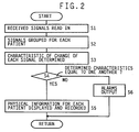
- Step S1 the CPU 56 of the control device 55 reads in the six physical-information signals and the respective device and information identification signals which have been received by the receiving circuit 50 and demodulated by the demodulating circuit 54.
- Step S1 is followed by Step S2 to class the six physical-information signals into a first signal group, G A , consisting of the ECG, oximeter, and PW signals for the patient A, and a second signal group, G B , consisting of the ECG, oximeter, and PW signals for the patient B, based on the respective device and information identification signals associated with the six physical-information signals.
- the CPU 56 evaluates a characteristic of change of each of the ECG, oximeter, and PW signals of each signal group G A , G B .
- the CPU 56 determines a period, T ECGA , of pulsation of the ECG signal, a period, T OXIA , of pulsation of the oximeter signal, and a period, T BPA , of pulsation of the PW signal, for the first signal group G A .
- the CPU 56 determines a period, T ECGB , of pulsation of the ECG signal, a period, T OXIB , of pulsation of the oximeter signal, and a period, T BPB , of pulsation of the PW signal, for the second signal group G B .
- Step S3 is followed by Step S4 to judge whether the three evaluated characteristics of each signal group G A , G B are substantially equal to one another.
- the CPU 56 judges whether the three determined periods T ECGA , T OXIA , T BPA , of the first signal group G A are substantially equal to one another and simultaneously judges whether the three determined periods T ECGB , T OXIB , T BPB , of the second signal group G B are substantially equal to one another.
- Step S4 the control of the CPU 56 proceeds with Step S5 to operate the output device 62 to display and record, based on the first signal group G A for the patient A, (A) the ECG waveform represented by the ECG signal of the group G A , (B) (b1) a curve representing the time-wise change of the blood oxygen saturation values and (b2) a current blood oxygen saturation value represented by the oximeter signal, and (C) (c1) the waveform of intra-arterial blood pressure represented by the PW signal and (c2) current systolic and diastolic blood pressure values corresponding to the upper and lower peaks of each pulse of the PW signal. Simultaneously, the output device 62 displays and records the same sorts of physical information for the patient B, based on the second signal group G B , separately from those for the patient A.
- Step S4 the control of the CPU 56 goes to Step S6 to output alarms indicating that the three evaluated characteristics of each signal group G A , G B are not equal to one another.
- the CPU 56 controls the output device 62 to display a visual alarm message specifying the particular detecting device 12a, 14a, 16a which has provided that one period different from the other two periods substantially equal to each other, and controls the display 62 to stop displaying all the sorts of physical information for the patient A.
- the CPU 56 controls the drive circuit 64 and the speaker 66 to output a sound alarm message specifying the particular detecting device 12a, 14a, 16a which has erroneously been worn on a patient other than the patient A.
- the CPU 56 operates the display 62 and the speaker 66 to output a visual and a sound alarm message each informing the medical worker of that erroneous wearing of the three detecting devices of a corresponding group (12a, 14a, 16a), (12b, 14b, 16b).
- Step S3 and a portion of the control device 56, 58, 60 for carrying out Step S3 function as characteristic determining means for determining the period T ECG of pulsation of the ECG signal, the period T OXI of pulsation of the oximeter signal, and the period T BP of pulsation of the PW signal, for each signal group G A , G B , and Step S4 and a portion of the control device 56, 58, 60 for carrying out Step S4 function as judging means for judging whether the three determined periods T ECG , T OXI , T BP for each patient A, B is substantially equal to each other.
- the CPU 56 identifies the particular detecting device 12 (12a, 12b), 14 (14a, 14b), 16 (16a, 16b) which has provided that one period different from the other two periods and judges that the thus identified particular detecting device 12, 14, 16 has erroneously been worn on the patient A, B.
- the present monitor system 10 ensures that a medical worker makes a correct decision and takes a quick action on each patient A, B by observing the physical sorts of information obtained from the patient A, B by the present system 10.
- FIG. 3 there is shown a second embodiment of the present invention.
- the second embodiment relates to a physical-information monitor system 100.
- a first, a second, and a third electrocardiograph (ECG) device 112a, 112b, 112c are worn on three patients A, B, C, respectively.
- the ECG devices 112a, 112b, 112c are identical with the ECG devices 12a, 12b shown in Fig. 1, and each ECG device 112a, 112b, 112c includes an ECG 122a, 122b, 122c and an ECG-signal transmitter 126a, 126b, 126c.
- Each of the ECG devices 112a, 112b, 112c transmits, by radio, an ECG signal to a monitor device 180.
- the monitor device 180 receives the ECG signal from each ECG device 112a, 112b, 112c and demodulates the received ECG signals.
- the monitor device 180 includes a screen 182 and displays, on the screen 182, the waveform or electrocardiogram (ECG) represented by the demodulated ECG signal for each of the patients A, B, C, separately from one another.
- ECG electrocardiogram
- a blood pressure (BP) monitor device 116 is worn, as needed, on one of the patents A, B, C.
- the BP monitor device 116 includes a BP monitor 134 and a PW-signal transmitter 138.
- the BP monitor device 116 employs a signal coding and transmitting techniques different from those employed by the ECG devices 112a, 112b, 112c, because the BP monitor device 116 and the ECG devices 112a, 112b, 112c may have been produced by different manufacturers, respectively.
- the monitor device 180 either cannot directly receive the ECG signals transmitted from the ECG devices 112a, 112b, 112c or, even if the monitor device 180 may receive the ECG signals, the received ECG signal may be too poor and therefore may not be used.
- the monitor system 100 further includes a signal receiving device 184 which has been produced by the same manufacturer as that for the BP monitor device 116 and which can receive, demodulate, and process a pulse wave (PW) signal transmitted from the BP monitor device 116.
- PW pulse wave
- the signal receiving device 184 has a select dial 186 which is operable or turnable by a medical worker for selecting one of the patients A, B, C (and additionally patients D and/or E, when appropriate) on whom the BP monitor device 116 has been worn or will be worn.
- the signal receiving device 184 receives the PW signal from the BP monitor device 116, processes the received PW signal into the waveform of intra-arterial blood pressure, and generates a BP digital signal representing the intra-arterial blood pressure (BP) waveform.
- the signal receiving device 184 also generates a patient (or bed) identification code or signal identifying a selected one patient A, B, C who is currently specified by the select dial 186 and on whom the BP monitor device 116 is currently set.
- the BP digital signal and patient identification signal generated by the signal receiving device 184 are compatible with a signal decoding technique employed by the monitor device 180.
- the present monitor system 100 operates according to the control program represented by the flow chart of Fig. 2, not for all the patients A, B, C but for only a selected one patient A, B, C who is currently specified by the select dial 186 and on whom the BP monitor device 116 is currently worn. More specifically, at Step S1, a CPU (not shown) of the monitor device 180 reads in the ECG signal supplied from one ECG device 112a, 112b, 112c worn on the selected patient A, B, C, and then at Step S2 the CPU associates the ECG signal with the BP digital signal supplied from the signal receiving device 184, based on the patient identification signal supplied from the signal receiving device 184 associated with the BP digital signal.
- Step S3 the CPU determines a period, T ECG , of pulsation of the ECG waveform represented by the ECG signal, and a period, T BP , of pulsation of the BP waveform represented by the BP digital signal. Subsequently, at Step S4, the CPU judges whether the two periods T ECG , T BP are substantially equal to each other. If a negative judgment is made at Step S4, the control of the CPU goes to Step S6 to display, on the screen 182 of the monitor device 180, a visual alarm message indicating that the patient currently specified by the select dial 186 is different from the patient currently wearing the BP monitor device 116. In addition, the CPU controls a sound output device (not shown) of the monitor device 180 to output a sound alarm message indicating the same.
- the present monitor system 100 ensures that a medical worker makes a correct decision and takes a quick action on each patient A, B, C by observing the sorts of physical information obtained from the patient A, B, C by the present system 10.
- the respective periods of pulsation of the ECG, oximeter, and PW (or BP) signals each corresponding to the period of heartbeat of each patient A, B are determined as the respective characteristics of change of a plurality of sorts of physical information.
- the respective waveforms of continuously detected intensities of the two lights represented by the oximeter signal, and the waveform of continuously detected intra-arterial blood pressure values represented by the PW signal each include a component changeable in synchronism with respiration of each patient A, B.
- the respective periods of change of the oximeter and PW signals each corresponding to the period of respiration of each patient A, B may be determined as the respective characteristics of change of a plurality of sorts of physical information, so as to identify whether the oximeter and PW signals are being obtained from one and same patient A or B.
- the respective amplitudes of successive pulses of each of the ECG-signal, oximeter-signal, and PW-signal waveforms obtained from one and same patient A, B must change similarly to each other. Therefore, the tendency of change (e.g., rate of change) of successively determined amplitudes of each of those signal waveforms may be determined as the characteristic of change of each of a plurality of sorts of physical information.
- the tendency of change (e.g., rates of change) of successively determined pulsation periods of each of the ECG-signal, oximeter-signal, and PW-signal waveforms may be determined as the characteristic of change of each of a plurality of sorts of physical information.
- the radio waves transmitted from the signal transmitters 26, 32, 38, 126, 138 are received by the signal receiving and output device 20 or monitor device 180 via a radio antenna and a receiving circuit
- the ECG, oximeter, or PW signal may be transmitted from each detector device 12, 14, 16, 112, 116 to the monitor device 20, 180, alternatively via a known signal cable, by optical communication as disclosed in Unexamined Japanese Utility Model Application laid open under Publication No. 61-78453, or via an electric-power line as disclosed in Unexamined Japanese Patent Application laid open under Publication No. 62-250728.
- the respective characteristics of change of a plurality of sorts of physical information are determined by the signal receiving and output device 20 or monitor device 180, it is possible to modify the ECG devices 12, 112, oximeter devices 14, and BP monitor devices 16, 116 so that the ECGs 22 (22a, 22b, ...) or 122 (122a, 122b, 122c, ...), oximeters 28 (28a, 28b, ...), and BP monitors 34 (34a, 34b, ...) or 116 each determine the respective periods T ECG , T OXI , T BP of the ECG, oximeter, and PW signals, and each of the signal transmitters 26 (26a, 26b, ...) or 126 (126a, 126b, 126c, ..), 32 (32a, 32b, ...), 38 (38a, 38b, ...) or 138 transmits, to the monitor device 20, 180, a corresponding one of the periods T ECG , T OXI , T BP together with
- the oximeter devices 14 (14a, 14b, ...) calculate the blood oxygen saturation values
- each of the oximeters 28 (28a, 28b, ...) obtains the respective waveforms of continuously detected intensities of the two transmitted or reflected lights having different frequencies and each of the oximeter-signal transmitters 32 (32a, 32b, ...) transmits a waveform signal representing only the respective waveforms of continuously detected intensities of the two lights.
- the signal receiving and output device 20 is modified to successively calculate blood oxygen saturation values based on the respective waveforms of continuously detected intensities of the two lights represented by the received waveform signal.
- ECG devices 12, 112, oximeter devices 14, and BP monitor devices 16, 116 are employed as the physical-information detecting devices, it is possible to employ an expirated-gas sensor, a carbonic-acid-gas sensor, and/or an invasive blood pressure measuring device using a catheter, all of which may be used on a patient undergoing a surgical operation, in addition to, or in place of, the illustrated devices 12, 112, 14, 16, 116.
Abstract
Description
- The present invention relates to a physical-information detecting system which obtains physical information from a living subject such as a patient.
- A plurality of physiological- or physical-information detecting devices such as an electrocardiograph (ECG), a blood pressure (BP) measuring device (e.g., BP monitor), and/or a blood oxygen saturation measuring device (i.e., oximeter) are used by being worn on each of a plurality of patients, so as to obtain an electrocardiogram, a blood pressure value, and/or a blood oxygen saturation value from the patient, respectively. The thus obtained various sorts of physical information are processed by a common physical-information output device, so that a visual representation of the various sorts of physical information is output for each patient on a display or a record sheet and so that a medical worker observes the plural sorts of physical information all at once.
- For example, a group of an ECG, a BP monitor, and an oximeter are worn on each of patients undergoing medical treatments in an intensive care unit (ICU) of a hospital, and three sorts of physical information are transmitted by radio, by optical communication, or alternatively by using respective electric signals from the three detectors to a center display device, so that the display device displays the plural sorts of physical information for each patient, separately from those for the other patients. With this monitor system, a medical worker such as a doctor or a nurse can read the plural sorts of physical information for each patient all at once.
- Each of the physical-information detectors generates a physical-information signal representing detected physical information, and an identification signal identifying the particular detector which provides that physical-information signal. The common output device processes the physical-information signal transmitted from each detector, and outputs a visual representation of the physical information represented by the processed signal.
- However, if one of the physical-information detectors is erroneously worn on an incorrect patient who is, for example, next to a correct patient to be monitored, the above-indicated, prior physical-information monitor system would output the physical information erroneously obtained from the incorrect patient, as the physical information of the correct patient to be monitored, because the prior monitor system does not identify each patient but only identifies each detector based on the identification signal supplied together with the physical-information signal from that particular detector.
- It is therefore an object of the present invention to provide a physical-information detecting system which includes a plurality of physical-information detectors and which judges whether or not the plurality of physical-information detectors are being worn on one and same living subject.
- The above object has been achieved by the present invention, which provides a physical-information detecting system comprising (a) a first detector which detects a first physical information of a first living subject and generates a first physical-information signal representing the detected first physical information, (b) a second detector which detects a second physical information of a second living subject and generates a second physical-information signal representing the detected second physical information, (c) a first transmitter which transmits the first physical-information signal, and a first identification signal identifying the first detector, (d) a second transmitter which transmits the second physical-information signal, and a second identification signal identifying the second detector, (e) a physical-information output device which receives the first and second physical-information signals and the first and second identification signals, from the first and second transmitters, and outputs the detected first physical information represented by the first physical-information signal and the detected second physical information represented by the second physical-information signal, (f) determining means for determining a characteristic of change of each of the first and second physical-information signals; and (g) judging means for judging whether the first and second living subjects are identical with each other, based on the respective determined characteristics of the first and second physical-information signals, the judging means providing a positive judgment when the respective determined characteristics are substantially identical with each other.
- In the physical-information detecting system constructed as described above, the determining means determines a characteristic of change of each of the first and second physical-information signals, and the judging means provides a positive judgment that the first and second living subjects are identical with each other, if the respective determined characteristics are substantially identical with each other. On the other hand, if the judging means provides a negative judgment that the first and second living subjects are different from each other, it means that the first and second detectors are not worn one and same living subject. In this case, the two detectors are worn on the two different subjects, respectively. The two detectors may be either ones which detect a same sort of physical information, or ones which detect different sorts of physical information, respectively.
- In a preferred embodiment in accordance with the present invention, the detecting system further comprising an alarm output device which outputs, when the judging means provides a negative judgment, an alarm indicating that the first and second detectors are worn on the first and second living subjects who are different from each other, respectively. In this case, a medical worker can quickly re-arrange the two detectors on a correct subject to be monitored.
- The above and optional objects, features, and advantages of the present invention will be better understood by reading the following detailed description of the preferred embodiments of the invention when considered in conjunction with the accompanying drawings, in which:
- Fig. 1 is a diagrammatic view of a physical-information monitor system to which the present invention is applied;
- Fig. 2 is a flow chart representing a control program according to which the monitor system of Fig. 1 operates; and
- Fig. 3 is a diagrammatic view corresponding to Fig. 1, illustrating another physical-information monitor system as a second embodiment of the present invention.
-
- Referring to Fig. 1, there is shown a physical-
information monitor system 10 to which the present invention is applied. Themonitor system 10 includes two or more groups of physical-information detecting and transmitting devices 12 (12a, 12b, ...), 14 (14a, 14b, ...), 16 (16a, 16b, ...) for two or more patients A, B, .... More specifically described, themonitor system 10 includes a first electrocardiograph (ECG)device 12a, a first oximeter device (i.e., blood oxygen saturation measuring device) 14a, and a first blood pressure (BP)monitor device 16a for a first patient A, and includes asecond ECG device 12b, asecond oximeter device 14b, and a secondBP monitor device 16b for a second patient B. The following description relates to the case where themonitor system 10 includes two groups of three physical-information detecting and transmitting devices 12 (12a, 12b), 14 (14a, 14b), 16 (16a, 16b) for two patients A and B. However, themonitor system 10 may be modified to include three or more groups of two, four, or more physical-information detecting and transmitting devices for three or more patients. - The first group of three physical-information detecting and transmitting
devices individual devices devices individual devices - The
present monitor system 10 further includes a physical-information receiving andoutput device 20 which receives the physical-information signal from each of the six physical-information detecting and transmittingdevices output device 20 processes the received physical-information signals, and displays and records the three sorts of physical-information for each of the two patients A, B separately from each other. - The constructions and functions of the first and
second ECG devices ECG device signal transmitter radio antenna 24a, 24b. The ECG signal has a waveform including a series of pulses corresponding to a series of heartbeats of the patient A, B. - The constructions and functions of the first and
second oximeter devices oximeter device oximeter signal transmitter radio antenna - The constructions and functions of the first and second
BP monitor devices BP monitor device signal transmitter radio antenna - Each of the six
signal transmitters device - The physical-information receiving and
output device 20 includes areceiving circuit 50 which receives, via aradio antenna 48, the physical-information signals supplied from therespective signal transmitters devices output device 20 further includes ademodulating circuit 54 which separates the six physical-information signals received by thereceiving circuit 50, from each other, based on the respective device and information identification signals received together with the physical-information signals. The demodulatingcircuit 54 outputs the thus separated physical-information signals via an analog-to-digital (A/D)converter 52 to acontrol device 55 including a microcomputer comprised of a central processing unit (CPU) 56, a random access memory (RAM) 58, and a read only memory (ROM) 60. TheCPU 56 processes the input signals according to control programs pre-stored in the ROM 60 by utilizing a temporary-storage function of theRAM 58. More specifically described, theCPU 56 processes the two ECG signals, the two oximeter signals, and the two PW signals, and operates anoutput device 62 to display, on a screen thereof, the ECG waveform, blood oxygen saturation values in digits, and waveform of intra-arterial blood pressure of each of the two patients A, B, separately from each other. In addition, theCPU 56 determines a characteristic of change of each of the ECG, oximeter, and PW signals supplied from each group of physical-information detecting and transmitting devices, i.e.,first group second group CPU 56 operates adrive circuit 64 to drive aspeaker 66 so as to output an alarm sound indicating that the three detecting and transmitting devices of the group (12a, 14a, 16a), (12b, 14b, 16b) in question are not worn on the one and same patient A or B but worn on the two patients A and B. In the present embodiment, the output of an alarm sound means that the three detecting and transmitting devices of thefirst group - The physical-information receiving and
output device 20 functions as characteristic determining means for determining a characteristic of change of the magnitudes of each of the ECG, oximeter, and PW signals supplied from each group (12a, 14a, 16a), (12b, 14b, 16b), by, e.g., determining the period of pulsation of each signal which corresponds to the period of heartbeat of a corresponding patient A, B, and also functions as judging means for judging whether the three detecting and transmitting devices of each group (12a, 14a, 16a), (12b, 14b, 16b) are worn on the one and same patient A or B, based on the determined periods of pulsation of the three signals supplied from each group (12a, 14a, 16a), (12b, 14b, 16b). In the case where the three detecting and transmitting devices of each group (12a, 14a, 16a), (12b, 14b, 16b) are worn on the one and same patient A or B, the respective periods of pulsation of the three signals supplied from each group (12a, 14a, 16a), (12b, 14b, 16b) must be substantially equal to one another. Therefore, if one of the three periods of pulsation is different from the other two periods of pulsation, the judging means provides a negative judgment. In this case, a medical worker such as a doctor or a nurse needs to re-arrange the detecting and transmitting devices of the group (12a, 14a, 16a), (12b, 14b, 16b) in question and properly puts those devices on an appropriate patient A or B. - Hereinafter, there will be described the operation of the physical-
information monitor system 10 constructed as described above, by reference to the flow chart of Fig. 2. - First, at Step S1, the
CPU 56 of thecontrol device 55 reads in the six physical-information signals and the respective device and information identification signals which have been received by thereceiving circuit 50 and demodulated by thedemodulating circuit 54. Step S1 is followed by Step S2 to class the six physical-information signals into a first signal group, GA, consisting of the ECG, oximeter, and PW signals for the patient A, and a second signal group, GB, consisting of the ECG, oximeter, and PW signals for the patient B, based on the respective device and information identification signals associated with the six physical-information signals. - At the following Step S3, the
CPU 56 evaluates a characteristic of change of each of the ECG, oximeter, and PW signals of each signal group GA, GB. In the present embodiment, theCPU 56 determines a period, TECGA, of pulsation of the ECG signal, a period, TOXIA, of pulsation of the oximeter signal, and a period, TBPA, of pulsation of the PW signal, for the first signal group GA. Similarly, theCPU 56 determines a period, TECGB, of pulsation of the ECG signal, a period, TOXIB, of pulsation of the oximeter signal, and a period, TBPB, of pulsation of the PW signal, for the second signal group GB. - Step S3 is followed by Step S4 to judge whether the three evaluated characteristics of each signal group GA, GB are substantially equal to one another. In the present embodiment, the
CPU 56 judges whether the three determined periods TECGA, TOXIA, TBPA, of the first signal group GA are substantially equal to one another and simultaneously judges whether the three determined periods TECGB, TOXIB, TBPB, of the second signal group GB are substantially equal to one another. - If a positive judgment is made at Step S4, the control of the
CPU 56 proceeds with Step S5 to operate theoutput device 62 to display and record, based on the first signal group GA for the patient A, (A) the ECG waveform represented by the ECG signal of the group GA, (B) (b1) a curve representing the time-wise change of the blood oxygen saturation values and (b2) a current blood oxygen saturation value represented by the oximeter signal, and (C) (c1) the waveform of intra-arterial blood pressure represented by the PW signal and (c2) current systolic and diastolic blood pressure values corresponding to the upper and lower peaks of each pulse of the PW signal. Simultaneously, theoutput device 62 displays and records the same sorts of physical information for the patient B, based on the second signal group GB, separately from those for the patient A. - On the other hand, if a negative judgment is made at Step S4, the control of the
CPU 56 goes to Step S6 to output alarms indicating that the three evaluated characteristics of each signal group GA, GB are not equal to one another. For example, in the case where one of the three determined periods TECGA, TOXIA, TBPA, for the patient A is different from the other two determined periods, theCPU 56 controls theoutput device 62 to display a visual alarm message specifying the particular detectingdevice display 62 to stop displaying all the sorts of physical information for the patient A. Alternatively, in this case, it is possible to stop displaying only the particular sort of physical information supplied from the particular detectingdevice CPU 56 controls thedrive circuit 64 and thespeaker 66 to output a sound alarm message specifying the particular detectingdevice CPU 56 operates thedisplay 62 and thespeaker 66 to output a visual and a sound alarm message each informing the medical worker of that erroneous wearing of the three detecting devices of a corresponding group (12a, 14a, 16a), (12b, 14b, 16b). - In the present embodiment, Step S3 and a portion of the
control device control device CPU 56 identifies the particular detecting device 12 (12a, 12b), 14 (14a, 14b), 16 (16a, 16b) which has provided that one period different from the other two periods and judges that the thus identified particular detecting device 12, 14, 16 has erroneously been worn on the patient A, B. Thus, thepresent monitor system 10 ensures that a medical worker makes a correct decision and takes a quick action on each patient A, B by observing the physical sorts of information obtained from the patient A, B by thepresent system 10. - Referring next to Fig. 3, there is shown a second embodiment of the present invention. The second embodiment relates to a physical-information monitor system 100.
- A first, a second, and a third electrocardiograph (ECG)
device ECG devices ECG devices ECG device ECG signal transmitter ECG devices monitor device 180. Themonitor device 180 receives the ECG signal from eachECG device monitor device 180 includes ascreen 182 and displays, on thescreen 182, the waveform or electrocardiogram (ECG) represented by the demodulated ECG signal for each of the patients A, B, C, separately from one another. - A blood pressure (BP)
monitor device 116 is worn, as needed, on one of the patents A, B, C. TheBP monitor device 116 includes aBP monitor 134 and a PW-signal transmitter 138. In the present embodiment, theBP monitor device 116 employs a signal coding and transmitting techniques different from those employed by theECG devices BP monitor device 116 and theECG devices monitor device 180 either cannot directly receive the ECG signals transmitted from theECG devices monitor device 180 may receive the ECG signals, the received ECG signal may be too poor and therefore may not be used. Hence, in the present embodiment, the monitor system 100 further includes asignal receiving device 184 which has been produced by the same manufacturer as that for theBP monitor device 116 and which can receive, demodulate, and process a pulse wave (PW) signal transmitted from theBP monitor device 116. - The
signal receiving device 184 has aselect dial 186 which is operable or turnable by a medical worker for selecting one of the patients A, B, C (and additionally patients D and/or E, when appropriate) on whom theBP monitor device 116 has been worn or will be worn. Thesignal receiving device 184 receives the PW signal from theBP monitor device 116, processes the received PW signal into the waveform of intra-arterial blood pressure, and generates a BP digital signal representing the intra-arterial blood pressure (BP) waveform. Thesignal receiving device 184 also generates a patient (or bed) identification code or signal identifying a selected one patient A, B, C who is currently specified by theselect dial 186 and on whom theBP monitor device 116 is currently set. The BP digital signal and patient identification signal generated by thesignal receiving device 184 are compatible with a signal decoding technique employed by themonitor device 180. - The present monitor system 100 operates according to the control program represented by the flow chart of Fig. 2, not for all the patients A, B, C but for only a selected one patient A, B, C who is currently specified by the
select dial 186 and on whom theBP monitor device 116 is currently worn. More specifically, at Step S1, a CPU (not shown) of themonitor device 180 reads in the ECG signal supplied from oneECG device signal receiving device 184, based on the patient identification signal supplied from thesignal receiving device 184 associated with the BP digital signal. At the following Step S3, the CPU determines a period, TECG, of pulsation of the ECG waveform represented by the ECG signal, and a period, TBP, of pulsation of the BP waveform represented by the BP digital signal. Subsequently, at Step S4, the CPU judges whether the two periods TECG, TBP are substantially equal to each other. If a negative judgment is made at Step S4, the control of the CPU goes to Step S6 to display, on thescreen 182 of themonitor device 180, a visual alarm message indicating that the patient currently specified by theselect dial 186 is different from the patient currently wearing theBP monitor device 116. In addition, the CPU controls a sound output device (not shown) of themonitor device 180 to output a sound alarm message indicating the same. - Also in the second embodiment, it is judged whether the respective characteristics of change of a plurality of sorts of physical information relating to a particular patient are substantially equal to each other. A negative judgment indicates either that the
BP monitor device 116 has been worn on a patient different from the particular patient or that theselect dial 186 has been turned to specify a patient different from that particular patient. Thus, the present monitor system 100 ensures that a medical worker makes a correct decision and takes a quick action on each patient A, B, C by observing the sorts of physical information obtained from the patient A, B, C by thepresent system 10. - While the present invention has been described in its preferred embodiments, the invention may otherwise be embodied.
- For example, in the illustrated embodiments, the respective periods of pulsation of the ECG, oximeter, and PW (or BP) signals each corresponding to the period of heartbeat of each patient A, B are determined as the respective characteristics of change of a plurality of sorts of physical information. However, the respective waveforms of continuously detected intensities of the two lights represented by the oximeter signal, and the waveform of continuously detected intra-arterial blood pressure values represented by the PW signal, each include a component changeable in synchronism with respiration of each patient A, B. In the case where the oximeter devices 28 and the BP monitor devices 34 are used, the respective periods of change of the oximeter and PW signals each corresponding to the period of respiration of each patient A, B may be determined as the respective characteristics of change of a plurality of sorts of physical information, so as to identify whether the oximeter and PW signals are being obtained from one and same patient A or B.
- In addition, the respective amplitudes of successive pulses of each of the ECG-signal, oximeter-signal, and PW-signal waveforms obtained from one and same patient A, B must change similarly to each other. Therefore, the tendency of change (e.g., rate of change) of successively determined amplitudes of each of those signal waveforms may be determined as the characteristic of change of each of a plurality of sorts of physical information.
- For the same reason, the tendency of change (e.g., rates of change) of successively determined pulsation periods of each of the ECG-signal, oximeter-signal, and PW-signal waveforms may be determined as the characteristic of change of each of a plurality of sorts of physical information.
- Although in the illustrated embodiments the radio waves transmitted from the
signal transmitters 26, 32, 38, 126, 138 are received by the signal receiving andoutput device 20 ormonitor device 180 via a radio antenna and a receiving circuit, the ECG, oximeter, or PW signal may be transmitted from eachdetector device 12, 14, 16, 112, 116 to themonitor device - While in the illustrated embodiments the respective characteristics of change of a plurality of sorts of physical information are determined by the signal receiving and
output device 20 ormonitor device 180, it is possible to modify the ECG devices 12, 112, oximeter devices 14, and BP monitordevices 16, 116 so that the ECGs 22 (22a, 22b, ...) or 122 (122a, 122b, 122c, ...), oximeters 28 (28a, 28b, ...), and BP monitors 34 (34a, 34b, ...) or 116 each determine the respective periods TECG, TOXI, TBP of the ECG, oximeter, and PW signals, and each of the signal transmitters 26 (26a, 26b, ...) or 126 (126a, 126b, 126c, ..), 32 (32a, 32b, ...), 38 (38a, 38b, ...) or 138 transmits, to themonitor device - Although in the first embodiment the oximeter devices 14 (14a, 14b, ...) calculate the blood oxygen saturation values, it is possible to adapt the oximeter devices 14 so that each of the oximeters 28 (28a, 28b, ...) obtains the respective waveforms of continuously detected intensities of the two transmitted or reflected lights having different frequencies and each of the oximeter-signal transmitters 32 (32a, 32b, ...) transmits a waveform signal representing only the respective waveforms of continuously detected intensities of the two lights. In this case, the signal receiving and
output device 20 is modified to successively calculate blood oxygen saturation values based on the respective waveforms of continuously detected intensities of the two lights represented by the received waveform signal. - While in the illustrated embodiments the ECG devices 12, 112, oximeter devices 14, and BP monitor
devices 16, 116 are employed as the physical-information detecting devices, it is possible to employ an expirated-gas sensor, a carbonic-acid-gas sensor, and/or an invasive blood pressure measuring device using a catheter, all of which may be used on a patient undergoing a surgical operation, in addition to, or in place of, the illustrateddevices 12, 112, 14, 16, 116. - It is to be understood that the present invention may be embodied with other changes, modifications, and improvements that may occur to those skilled in the art without departing from the scope and spirit of the invention defined in the appended claims.
Claims (20)
- A physical-information detecting system (10, 100) comprising:
a first detector (22a; 122a) which detects a first physical information of a first living subject and generates a first physical-information signal representing the detected first physical information;
a second detector (34a; 134) which detects a second physical information of a second living subject and generates a second physical-information signal representing the detected second physical information;
a first transmitter (26a; 126a) which transmits said first physical-information signal, and a first identification signal identifying said first detector (22a; 122a);
a second transmitter (38a; 138) which transmits said second physical-information signal, and a second identification signal identifying said second detector (34a; 134);
a physical-information output device (20, 180) which receives said first and second physical-information signals and said first and second identification signals, from said first and second transmitters (26a, 38a; 126a, 138), and outputs said detected first physical information represented by said first physical-information signal and said detected second physical information represented by said second physical-information signal;
determining means (56, S3) for determining a characteristic of change of each of said first and second physical-information signals; and
judging means (56, S4) for judging whether said first and second living subjects are identical with each other, based on the respective determined characteristics of said first and second physical-information signals, said judging means providing a positive judgment when said respective determined characteristics are substantially identical with each other. - A detecting system according to claim 1, wherein said first and second detectors comprise one of an electrocardiograph (22a; 122a), a blood pressure measuring device (34a; 134), and a blood oxygen saturation measuring device (28a).
- A detecting system according to claim 1 or claim 2, wherein said determining means comprises means (56, S3) for determining, as said characteristic of change of said each of said first and second physical-information signals, a period of pulsation of said each physical-information signal that is equal to a period of heartbeat of a corresponding one of said first and second living subjects,
said judging means (56, S4) providing said positive judgment when the respective determined pulsation periods of said first and second physical-information signals are substantially equal to each other. - A detecting system according to any of claims 1 to 3, wherein said first detector (22a; 122a) detects, as said first physical information, a first sort of physical information of said first living subject, and said second detector (34a; 134) detects, as said second physical information, a second sort of physical information of said second living subject, said first and second sorts being different from each other.
- A detecting system according to claim 4, further comprising:
a third detector (28a) which detects a third sort of physical information of a third living subject and generates a third physical-information signal representing the detected third physical information, said third sort being different from said first and second sorts; and
a third transmitter (32a) which transmits said third physical-information signal, and a third identification signal identifying said third detector,
said physical-information output device (20) receiving said third physical-information signal and said third identification signal from said third transmitter (32a) and outputs said detected third physical information represented by said third physical-information signal,
said determining means (56, S3) determining a characteristic of change of said third physical-information signal,
said judging means (56, S4) judging whether said first, second, and third living subjects are identical with one another, based on the respective determined characteristics of said first, second, and third physical-information signals, said judging means providing a positive judgment when said respective determined characteristics of said first, second, and third physical-information signals are substantially identical with one another. - A detecting system according to claim 5, wherein said first, second, and third detectors comprise a first, a second, and a third one of an electrocardiograph (22a), a blood pressure measuring device (34a), and a blood oxygen saturation measuring device (28a), respectively.
- A detecting system according to claim 5 or claim 6, wherein said judging means comprises means (56, S4) for judging that each of said first, second, and third living subjects is different from the other living subjects, when a corresponding one of said respective determined characteristics of said first, second, and third physical-information signals is different from the other determined characteristics.
- A detecting system according to claim 7, further comprising an informing device (62, 66; 182) which informs an operator of one of said first, second, and third detectors (22a, 28a, 34a), which corresponds to said one of said first, second, and third living subjects.
- A detecting system according to claim 7 or claim 8, further comprising a control device (56, S6) which controls said physical-information output device (20) to stop outputting one of said first, second, and third physical information which corresponds to said one of said first, second, and third living subjects.
- A detecting system according to any of claims 4 through 9, further comprising:
a third detector (22b) which detects a third sort of physical information of a third living subject and generates a third physical-information signal representing the detected third physical information, said third sort being same as said first sort and different from said second sort;
a fourth detector (34b) which detects a fourth sort of physical information of a fourth living subject and generates a fourth physical-information signal representing the detected fourth physical information, said fourth sort being different from said first sort and same as said second sort;
a third transmitter (26b) which transmits said third physical-information signal, and a third identification signal identifying said third detector; and
a fourth transmitter (38b) which transmits said fourth physical-information signal, and a fourth identification signal identifying said fourth detector,
said physical-information output device (20) receiving said third and fourth physical-information signals and said third and fourth identification signals, from said third and fourth transmitters (26b, 38b), and outputting, separately from a first group of said detected first and second physical information represented by said first and second physical-information signals, a second group of said detected third physical information represented by said third physical-information signal and said detected fourth physical information represented by said fourth physical-information signal, based on said first, second, third, and fourth identification signals,
said determining means (56, S3) determining a characteristic of change of each of said third and fourth physical-information signals,
said judging means (56, S4) judging whether said third and fourth living subjects are identical with each other, based on the respective determined characteristics of said third and fourth physical-information signals, said judging means providing a positive judgment when said respective determined characteristics of said third and fourth physical-information signals are substantially identical with each other. - A detecting system according to claim 10, further comprising a memory (58) which stores said first group of said detected first and second physical information, and said second group of said detected third and fourth physical information, separately from each other.
- A detecting system according to any of claims 1 through 11, further comprising an alarm output device (62, 66; 182) which outputs, when said judging means makes a negative judgment, an alarm indicating that said first and second detectors (22a, 34a; 122a, 134) are worn on said first and second living subjects who are different from each other, respectively.
- A detecting system according to claim 12, wherein said alarm output device comprises a sound output device (66) which outputs a sound as said alarm.
- A detecting system according to claim 12 or claim 13, wherein said alarm output device comprises a display (62; 182) which displays a message as said alarm.
- A detecting system according to any of claims 1 through 14, further comprising a control device (56, S6) which controls, when said judging means (56, S4) makes a negative judgment, said physical-information output device (20, 180) to stop outputting said detected first and second physical information.
- A detecting system according to any of claims 1 through 15, further comprising:
a selecting device (186) which is operable for selecting one of said first and second living subjects; and
a signal receiver (184) which receives one of said first and second physical-information signals from a corresponding one of said first and second transmitters (126a, 138) and supplies, to said physical-information output device (180), the received one physical-information signal and one of said first and second identification signals which corresponds to the selected one living subject,
said physical-information output device (180) receiving said one physical-information signal via said signal receiver (184) from said corresponding one transmitter (126a, 138), and said one identification signal from said signal receiver, in addition to the other of said first and second physical-information signals and one of said first and second identification signals which corresponds to said other physical-information signal;
said determining means (180, S3) determining the characteristic of change of said one physical-information signal supplied from said signal receiver (184), in addition to the characteristic of change of said other physical-information signal,
said judging means (180, S4) providing a positive judgment that said selected one living subject and the other of said first and second living subjects are identical with each other, when the respective determined characteristics of said one and other physical-information signals are substantially identical with each other. - A detecting system according to claim 16, further comprising an alarm output device (182) which outputs, when said judging means (180, S4) provides a negative judgment, an alarm indicating that said first and second detectors (122a, 134) are worn on said first and second living subjects who are different from each other, respectively.
- A detecting system according to any of claims 1 through 17, wherein said determining means comprises means (56, S3) for determining said characteristic of change of said each of said first and second physical-information signals received by said physical-information output device (20, 180).
- A detecting system according to any of claims 1 through 18, wherein said physical-information output device (20, 180) comprises at least one of (a) a display (62, 182) which displays said detected first and second physical information represented by said first and second physical-information signals and (b) a recorder which records, on a recording medium, said detected first and second physical information.
- A detecting system according to any of claims 1 through 19, wherein said first and second transmitters (26a, 38a) transmit, by radio, said first and second physical-information signals and said first and second identification signals, and said physical-information output device (20) comprises a signal receiver (50) which receives, by radio, said first and second physical-information signals and said first and second identification signals from said first and second transmitters.
Applications Claiming Priority (2)
| Application Number | Priority Date | Filing Date | Title |
|---|---|---|---|
| JP298385/93 | 1993-11-29 | ||
| JP29838593A JP3241512B2 (en) | 1993-11-29 | 1993-11-29 | Biological information measurement device |
Publications (2)
| Publication Number | Publication Date |
|---|---|
| EP0655218A1 true EP0655218A1 (en) | 1995-05-31 |
| EP0655218B1 EP0655218B1 (en) | 1999-04-07 |
Family
ID=17859019
Family Applications (1)
| Application Number | Title | Priority Date | Filing Date |
|---|---|---|---|
| EP94118518A Expired - Lifetime EP0655218B1 (en) | 1993-11-29 | 1994-11-24 | Physical-information detecting system |
Country Status (4)
| Country | Link |
|---|---|
| US (1) | US5586552A (en) |
| EP (1) | EP0655218B1 (en) |
| JP (1) | JP3241512B2 (en) |
| DE (1) | DE69417690T2 (en) |
Cited By (2)
| Publication number | Priority date | Publication date | Assignee | Title |
|---|---|---|---|---|
| EP1192895A1 (en) * | 2000-09-27 | 2002-04-03 | Wei-Kang Lin | Remote medical monitoring method and system |
| US6847294B1 (en) | 1999-12-16 | 2005-01-25 | Wei-Kang Lin | Radio medical monitoring method and radio medical monitoring system |
Families Citing this family (14)
| Publication number | Priority date | Publication date | Assignee | Title |
|---|---|---|---|---|
| DE4329898A1 (en) | 1993-09-04 | 1995-04-06 | Marcus Dr Besson | Wireless medical diagnostic and monitoring device |
| JP3206461B2 (en) * | 1996-12-02 | 2001-09-10 | 富士通株式会社 | Home care support system |
| US6047201A (en) * | 1998-04-02 | 2000-04-04 | Jackson, Iii; William H. | Infant blood oxygen monitor and SIDS warning device |
| US6494829B1 (en) * | 1999-04-15 | 2002-12-17 | Nexan Limited | Physiological sensor array |
| DE10214459A1 (en) * | 2001-04-05 | 2003-04-30 | Univ Ilmenau Tech | Arrangement and method for the detection of signals of biological origin |
| US7197357B2 (en) * | 2001-07-17 | 2007-03-27 | Life Sync Corporation | Wireless ECG system |
| US7933642B2 (en) | 2001-07-17 | 2011-04-26 | Rud Istvan | Wireless ECG system |
| US20030107487A1 (en) * | 2001-12-10 | 2003-06-12 | Ronen Korman | Method and device for measuring physiological parameters at the wrist |
| JP3945499B2 (en) * | 2003-09-30 | 2007-07-18 | セイコーエプソン株式会社 | Divers information processing apparatus, divers information processing apparatus control method, control program, and recording medium |
| JP4296570B2 (en) * | 2003-12-08 | 2009-07-15 | 日本光電工業株式会社 | Vital telemeter |
| US20130321168A1 (en) * | 2011-02-22 | 2013-12-05 | Joelmar Pty Ltd. | Survival and location enhancement garment and headgear |
| JP2012200266A (en) * | 2011-03-23 | 2012-10-22 | Omron Healthcare Co Ltd | Control device and authentication method |
| US20130144536A1 (en) * | 2011-12-06 | 2013-06-06 | Welch Allyn, Inc. | Medical Device with Wireless Communication Bus |
| JP6220816B2 (en) * | 2015-06-12 | 2017-10-25 | ミヨシ電子株式会社 | Location information management system |
Citations (3)
| Publication number | Priority date | Publication date | Assignee | Title |
|---|---|---|---|---|
| US3572316A (en) * | 1968-02-23 | 1971-03-23 | Chromalloy American Corp | Physiological signal monitoring system |
| GB2003276A (en) * | 1977-08-29 | 1979-03-07 | Karz A | Continuous electrocardiogram monitoring method and system for cardiac patients |
| DE3525014A1 (en) * | 1985-07-12 | 1987-01-15 | Mueller Wickop Juergen Dr | Patient monitoring system |
Family Cites Families (11)
| Publication number | Priority date | Publication date | Assignee | Title |
|---|---|---|---|---|
| JPS5326437A (en) * | 1976-08-24 | 1978-03-11 | Kenzou Shigiyou | Method of removing parasites from steel structure in sea |
| JPS6178453A (en) * | 1984-09-21 | 1986-04-22 | Kurieito Syst Kk | Electrostatic painting apparatus |
| JPS62250728A (en) * | 1986-04-24 | 1987-10-31 | Nippon Colin Co Ltd | Power source line coupler |
| JPH0642914B2 (en) * | 1988-05-16 | 1994-06-08 | ユニバーサル販売株式会社 | Gaming machine controller |
| JPH02111343A (en) * | 1988-10-21 | 1990-04-24 | Koorin Denshi Kk | Reflecting oxymeter |
| JP3039934B2 (en) * | 1989-06-13 | 2000-05-08 | コーリン電子株式会社 | Pressure pulse wave detector |
| JP2766317B2 (en) * | 1989-06-22 | 1998-06-18 | コーリン電子株式会社 | Pulse oximeter |
| US5050613A (en) * | 1989-09-15 | 1991-09-24 | Imex Corporation | Method and apparatus for vascular testing |
| US5152296A (en) * | 1990-03-01 | 1992-10-06 | Hewlett-Packard Company | Dual-finger vital signs monitor |
| US5179956A (en) * | 1990-07-06 | 1993-01-19 | Colin Electronics Co., Ltd. | Contact pressure sensor |
| US5253645A (en) * | 1991-12-13 | 1993-10-19 | Critikon, Inc. | Method of producing an audible alarm in a blood pressure and pulse oximeter monitor |
-
1993
- 1993-11-29 JP JP29838593A patent/JP3241512B2/en not_active Expired - Fee Related
-
1994
- 1994-11-16 US US08/341,989 patent/US5586552A/en not_active Expired - Lifetime
- 1994-11-24 EP EP94118518A patent/EP0655218B1/en not_active Expired - Lifetime
- 1994-11-24 DE DE69417690T patent/DE69417690T2/en not_active Expired - Fee Related
Patent Citations (3)
| Publication number | Priority date | Publication date | Assignee | Title |
|---|---|---|---|---|
| US3572316A (en) * | 1968-02-23 | 1971-03-23 | Chromalloy American Corp | Physiological signal monitoring system |
| GB2003276A (en) * | 1977-08-29 | 1979-03-07 | Karz A | Continuous electrocardiogram monitoring method and system for cardiac patients |
| DE3525014A1 (en) * | 1985-07-12 | 1987-01-15 | Mueller Wickop Juergen Dr | Patient monitoring system |
Cited By (2)
| Publication number | Priority date | Publication date | Assignee | Title |
|---|---|---|---|---|
| US6847294B1 (en) | 1999-12-16 | 2005-01-25 | Wei-Kang Lin | Radio medical monitoring method and radio medical monitoring system |
| EP1192895A1 (en) * | 2000-09-27 | 2002-04-03 | Wei-Kang Lin | Remote medical monitoring method and system |
Also Published As
| Publication number | Publication date |
|---|---|
| US5586552A (en) | 1996-12-24 |
| JPH07148121A (en) | 1995-06-13 |
| DE69417690D1 (en) | 1999-05-12 |
| EP0655218B1 (en) | 1999-04-07 |
| DE69417690T2 (en) | 1999-12-02 |
| JP3241512B2 (en) | 2001-12-25 |
Similar Documents
| Publication | Publication Date | Title |
|---|---|---|
| EP0655218B1 (en) | Physical-information detecting system | |
| US6319200B1 (en) | Method and system for remotely monitoring multiple medical parameters | |
| US10709330B2 (en) | Ambulatory medical telemetry device having an audio indicator | |
| US5682898A (en) | Respiration rate measuring apparatus | |
| US5036869A (en) | Medical wireless telemeter | |
| US6801802B2 (en) | System and method for selecting physiological data from a plurality of physiological data sources | |
| US5729203A (en) | Emergency call system | |
| US6491638B2 (en) | Circulation-condition monitoring apparatus | |
| EP1897028B1 (en) | Method and apparatus for distinguishing between clinically significant changes and artifacts in patient physiological information | |
| US9492099B2 (en) | System and method for facilitating reflectometric detection of physiologic activity | |
| GB2259772A (en) | Biological signal monitor and transmitter | |
| JP2003220045A (en) | Observation device and method for patient by noninvasive cardiac output observation | |
| AU718891B2 (en) | Automatic lead switching for ECG monitor | |
| US5653241A (en) | Blood-pressure monitor apparatus | |
| US6582374B2 (en) | Automatic blood-pressure measuring apparatus | |
| KR0133460B1 (en) | Self health diagnosis method and circuit for television | |
| US6406434B2 (en) | Blood-pressure measuring apparatus for patient under blood-dialysis treatment | |
| US6921368B2 (en) | Blood pressure monitor apparatus | |
| US5203342A (en) | Peripheral blood circulation state detecting apparatus | |
| US6482163B2 (en) | Postoperative-condition evaluating apparatus | |
| JP2773694B2 (en) | Medical telemeter system | |
| US6011989A (en) | Patient monitoring apparatus | |
| JPH05161611A (en) | Medical telemeter device | |
| JPH05245117A (en) | Medical communication equipment | |
| JPH06142065A (en) | Organic information measuring apparatus |
Legal Events
| Date | Code | Title | Description |
|---|---|---|---|
| PUAI | Public reference made under article 153(3) epc to a published international application that has entered the european phase |
Free format text: ORIGINAL CODE: 0009012 |
|
| AK | Designated contracting states |
Kind code of ref document: A1 Designated state(s): DE FR GB |
|
| 17P | Request for examination filed |
Effective date: 19951030 |
|
| GRAG | Despatch of communication of intention to grant |
Free format text: ORIGINAL CODE: EPIDOS AGRA |
|
| 17Q | First examination report despatched |
Effective date: 19980612 |
|
| GRAG | Despatch of communication of intention to grant |
Free format text: ORIGINAL CODE: EPIDOS AGRA |
|
| GRAH | Despatch of communication of intention to grant a patent |
Free format text: ORIGINAL CODE: EPIDOS IGRA |
|
| GRAH | Despatch of communication of intention to grant a patent |
Free format text: ORIGINAL CODE: EPIDOS IGRA |
|
| GRAA | (expected) grant |
Free format text: ORIGINAL CODE: 0009210 |
|
| AK | Designated contracting states |
Kind code of ref document: B1 Designated state(s): DE FR GB |
|
| REF | Corresponds to: |
Ref document number: 69417690 Country of ref document: DE Date of ref document: 19990512 |
|
| ET | Fr: translation filed | ||
| PLBE | No opposition filed within time limit |
Free format text: ORIGINAL CODE: 0009261 |
|
| STAA | Information on the status of an ep patent application or granted ep patent |
Free format text: STATUS: NO OPPOSITION FILED WITHIN TIME LIMIT |
|
| 26N | No opposition filed | ||
| REG | Reference to a national code |
Ref country code: GB Ref legal event code: IF02 |
|
| PGFP | Annual fee paid to national office [announced via postgrant information from national office to epo] |
Ref country code: GB Payment date: 20021120 Year of fee payment: 9 |
|
| PGFP | Annual fee paid to national office [announced via postgrant information from national office to epo] |
Ref country code: FR Payment date: 20021128 Year of fee payment: 9 |
|
| PGFP | Annual fee paid to national office [announced via postgrant information from national office to epo] |
Ref country code: DE Payment date: 20030129 Year of fee payment: 9 |
|
| PG25 | Lapsed in a contracting state [announced via postgrant information from national office to epo] |
Ref country code: GB Free format text: LAPSE BECAUSE OF NON-PAYMENT OF DUE FEES Effective date: 20031124 |
|
| PG25 | Lapsed in a contracting state [announced via postgrant information from national office to epo] |
Ref country code: DE Free format text: LAPSE BECAUSE OF NON-PAYMENT OF DUE FEES Effective date: 20040602 |
|
| GBPC | Gb: european patent ceased through non-payment of renewal fee |
Effective date: 20031124 |
|
| PG25 | Lapsed in a contracting state [announced via postgrant information from national office to epo] |
Ref country code: FR Free format text: LAPSE BECAUSE OF NON-PAYMENT OF DUE FEES Effective date: 20040730 |
|
| REG | Reference to a national code |
Ref country code: FR Ref legal event code: ST |