EP0654383A2 - Vehicle controler - Google Patents
Vehicle controler Download PDFInfo
- Publication number
- EP0654383A2 EP0654383A2 EP94117450A EP94117450A EP0654383A2 EP 0654383 A2 EP0654383 A2 EP 0654383A2 EP 94117450 A EP94117450 A EP 94117450A EP 94117450 A EP94117450 A EP 94117450A EP 0654383 A2 EP0654383 A2 EP 0654383A2
- Authority
- EP
- European Patent Office
- Prior art keywords
- engine
- control unit
- key card
- card
- vehicle
- Prior art date
- Legal status (The legal status is an assumption and is not a legal conclusion. Google has not performed a legal analysis and makes no representation as to the accuracy of the status listed.)
- Granted
Links
Images


Classifications
-
- B—PERFORMING OPERATIONS; TRANSPORTING
- B60—VEHICLES IN GENERAL
- B60R—VEHICLES, VEHICLE FITTINGS, OR VEHICLE PARTS, NOT OTHERWISE PROVIDED FOR
- B60R25/00—Fittings or systems for preventing or indicating unauthorised use or theft of vehicles
- B60R25/01—Fittings or systems for preventing or indicating unauthorised use or theft of vehicles operating on vehicle systems or fittings, e.g. on doors, seats or windscreens
- B60R25/02—Fittings or systems for preventing or indicating unauthorised use or theft of vehicles operating on vehicle systems or fittings, e.g. on doors, seats or windscreens operating on the steering mechanism
- B60R25/021—Fittings or systems for preventing or indicating unauthorised use or theft of vehicles operating on vehicle systems or fittings, e.g. on doors, seats or windscreens operating on the steering mechanism restraining movement of the steering column or steering wheel hub, e.g. restraining means controlled by ignition switch
- B60R25/0215—Fittings or systems for preventing or indicating unauthorised use or theft of vehicles operating on vehicle systems or fittings, e.g. on doors, seats or windscreens operating on the steering mechanism restraining movement of the steering column or steering wheel hub, e.g. restraining means controlled by ignition switch using electric means, e.g. electric motors or solenoids
- B60R25/02153—Fittings or systems for preventing or indicating unauthorised use or theft of vehicles operating on vehicle systems or fittings, e.g. on doors, seats or windscreens operating on the steering mechanism restraining movement of the steering column or steering wheel hub, e.g. restraining means controlled by ignition switch using electric means, e.g. electric motors or solenoids comprising a locking member radially and linearly moved towards the steering column
-
- B—PERFORMING OPERATIONS; TRANSPORTING
- B60—VEHICLES IN GENERAL
- B60R—VEHICLES, VEHICLE FITTINGS, OR VEHICLE PARTS, NOT OTHERWISE PROVIDED FOR
- B60R25/00—Fittings or systems for preventing or indicating unauthorised use or theft of vehicles
- B60R25/01—Fittings or systems for preventing or indicating unauthorised use or theft of vehicles operating on vehicle systems or fittings, e.g. on doors, seats or windscreens
- B60R25/04—Fittings or systems for preventing or indicating unauthorised use or theft of vehicles operating on vehicle systems or fittings, e.g. on doors, seats or windscreens operating on the propulsion system, e.g. engine or drive motor
-
- B—PERFORMING OPERATIONS; TRANSPORTING
- B60—VEHICLES IN GENERAL
- B60R—VEHICLES, VEHICLE FITTINGS, OR VEHICLE PARTS, NOT OTHERWISE PROVIDED FOR
- B60R25/00—Fittings or systems for preventing or indicating unauthorised use or theft of vehicles
- B60R25/20—Means to switch the anti-theft system on or off
- B60R25/24—Means to switch the anti-theft system on or off using electronic identifiers containing a code not memorised by the user
- B60R25/248—Electronic key extraction prevention
-
- B—PERFORMING OPERATIONS; TRANSPORTING
- B62—LAND VEHICLES FOR TRAVELLING OTHERWISE THAN ON RAILS
- B62H—CYCLE STANDS; SUPPORTS OR HOLDERS FOR PARKING OR STORING CYCLES; APPLIANCES PREVENTING OR INDICATING UNAUTHORIZED USE OR THEFT OF CYCLES; LOCKS INTEGRAL WITH CYCLES; DEVICES FOR LEARNING TO RIDE CYCLES
- B62H5/00—Appliances preventing or indicating unauthorised use or theft of cycles; Locks integral with cycles
- B62H5/20—Appliances preventing or indicating unauthorised use or theft of cycles; Locks integral with cycles indicating unauthorised use, e.g. acting on signalling devices
-
- G—PHYSICS
- G05—CONTROLLING; REGULATING
- G05B—CONTROL OR REGULATING SYSTEMS IN GENERAL; FUNCTIONAL ELEMENTS OF SUCH SYSTEMS; MONITORING OR TESTING ARRANGEMENTS FOR SUCH SYSTEMS OR ELEMENTS
- G05B19/00—Programme-control systems
- G05B19/02—Programme-control systems electric
- G05B19/04—Programme control other than numerical control, i.e. in sequence controllers or logic controllers
- G05B19/12—Programme control other than numerical control, i.e. in sequence controllers or logic controllers using record carriers
- G05B19/16—Programme control other than numerical control, i.e. in sequence controllers or logic controllers using record carriers using magnetic record carriers
-
- B—PERFORMING OPERATIONS; TRANSPORTING
- B60—VEHICLES IN GENERAL
- B60R—VEHICLES, VEHICLE FITTINGS, OR VEHICLE PARTS, NOT OTHERWISE PROVIDED FOR
- B60R2325/00—Indexing scheme relating to vehicle anti-theft devices
- B60R2325/30—Vehicles applying the vehicle anti-theft devices
- B60R2325/306—Motorcycles
-
- G—PHYSICS
- G05—CONTROLLING; REGULATING
- G05B—CONTROL OR REGULATING SYSTEMS IN GENERAL; FUNCTIONAL ELEMENTS OF SUCH SYSTEMS; MONITORING OR TESTING ARRANGEMENTS FOR SUCH SYSTEMS OR ELEMENTS
- G05B2219/00—Program-control systems
- G05B2219/20—Pc systems
- G05B2219/23—Pc programming
- G05B2219/23355—Magnetic card
-
- G—PHYSICS
- G05—CONTROLLING; REGULATING
- G05B—CONTROL OR REGULATING SYSTEMS IN GENERAL; FUNCTIONAL ELEMENTS OF SUCH SYSTEMS; MONITORING OR TESTING ARRANGEMENTS FOR SUCH SYSTEMS OR ELEMENTS
- G05B2219/00—Program-control systems
- G05B2219/20—Pc systems
- G05B2219/26—Pc applications
- G05B2219/2637—Vehicle, car, auto, wheelchair
Definitions
- the present invention relates to a vehicle controller comprising an engine control unit provided with an electric circuit for starting and stopping the engine of a vehicle, and a key for controlling the operation of the engine in cooperation with the engine control unit.
- a mechanical ignition key is used for starting and stopping the engine of, for example, a motorcycle.
- the engine is started by means of an engine starting arrangement that is operated with such a mechanical ignition key, it is possible to start the engine unduly without using the ignition key.
- An expensive, complicated, preventive arrangement is necessary for preventing undue starting of the engine. Accordingly, the computerized control of starting and stopping of the engine has been desired in recent years.
- ignition timing for timing the ignition system of an engine is varied according to the condition and the service condition of the engine and, therefore, data for the computerized control of ignition timing stored in a ROM must be changed.
- An apparatus disclosed in Japanese Patent Laid-open (Kokai) No. 2-191870 stores adjusting data for changing parameters for timing ignition in a data storage means, changes the adjusting data stored in the data storage means for new adjusting data transmitted to the data storage means according to instructions given by a communicating means.
- this known apparatus simply rewrites the adjusting data for changing the parameters for determining the ignition time and hence the data can be changed in very narrow ranges. Consequently, the apparatus is unable to change the vehicle control data optionally and has difficulty in effectively responding to user's requests varying in wide ranges.
- the present invention has been made to solve such problems and it is therefore an object of the present invention to provide a controller for a vehicle, capable of simply and surely changing control data necessary for the operation of an engine control unit for starting and stopping the engine.
- the present invention provides an engine controller comprising: an engine control unit provided with an electric circuit for starting and stopping the engine of a vehicle mounted on the body frame of the vehicle; and a key card that controls the operation of the engine in cooperation with the engine control unit; characterized in that the key card comprises; a storage means capable of storing all the data necessary for the operation of the engine control unit, and a data rewriting means for destroying all the control data stored beforehand in the engine control unit and writing the control data stored in the storage means on the engine control unit.
- the power supply of the vehicle is turned on and all the control data stored beforehand in the engine control unit is changed for the control data stored in the storage means of the key card when the key card is loaded into the engine control unit. Accordingly, the control data can be optionally and easily changed according to user's requests.
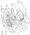
- Figs. 1 and 2 are fragmentary views of a motorcycle 300 incorporating a vehicle controller in a preferred embodiment according to the present invention.
- the motorcycle 300 has a body frame 302.
- the body frame 302 has a head frame 304 transversely expanding toward the rear as shown in Fig. 3.
- the head frame 304 defines a chamber 306 opening toward the rear.
- the head frame 304 has a hole 308 opening into the front portion of the chamber 306, and is provided in its rear end with brackets 310a and 310b provided respectively with threaded holes 312a and 312b.
- Main frames 314a and 314b extend backward from the opposite sides of the rear end of the head frame 304.
- a steering bar 317 is joined to the upper end of a front fork 540, a front fender 542 is fastened to the lower portion of the front fork 540, and a front wheel is held for rotation on the lower end of the front fork 540.
- the front side of the steering bar 317 is covered with a fairing 546.
- a headlight 548, rearview mirrors 550 and a screen 552 are held on the fairing 546.
- a fuel tank 554 is mounted on the main frames 314a and 314b, and a seat 556 is disposed behind the fuel tank 554.
- indicated at 558 is a top bridge disposed on the side of the steering bar 317.
- a steering bar locking unit 316 is placed within the chamber 306 of the head frame 304.
- the steering bar locking unit 316 has a housing 320 held in the chamber 304 of the head frame 304 so as to receive a stem pipe 318 that turns together with the steering bar 317.
- Contained in the housing 320 are a steering bar locking member 322 capable of being moved between a locking position where the locking member 322 engages the stem pipe 318 to lock the steering bar 317 and a releasing position where the locking member 322 releases the stem pipe 318 to allow the steering bar 317 to turn, a rotating member 324 that is turned in the direction of the arrow A (Fig.
- a driving device 323 for turning the rotating member 324 in angular steps through a first position (ON position shown in Fig. 6A) to allow the steering bar 317 to turn and the engine to operate, a second position (OFF position shown in Fig. 6B) to allow the steering bar 317 to turn and to inhibit the engine from operating, and a third position (locking position shown in Fig. 6C) to lock the steering bar 317.
- the driving device 323 comprises a spring 325 for biasing the rotating member 324 in the direction indicated by the arrow B opposite the direction indicated by the arrow A, a retaining member 326 for retaining the rotating member 324 at a predetermined angular position, and a solenoid 328 that is actuated when a starter switch is closed to disengage the retaining member 326 from the rotating member 324 to enable the rotating member 324 to be turned stepwise from the first position through the second position to the third position.
- the housing 320 has a case 330, an inner lid 332 and a cover 334.
- the housing 320 is provided with a through hole 336 for receiving the stem pipe 318.
- a pin 338 to be fitted in a hole 308 formed in the head pipe 304 projects from the front end of the case 330.
- Projections 340a and 340b are formed on the rear end of the case 330 at positions respectively corresponding to the brackets 310a and 310b of the head frame 304, and holes 342a and 342b are formed in the projections 340a and 340b so as to correspond to the threaded holes 312a and 312b, respectively, as shown in Fig. 3.
- bolts 343a and 343b are inserted through the holes 432a and 342b and screwed in the threaded holes 312a and 312b, respectively, to fasten the housing 320 to the head frame 304.
- the cylindrical locking member 322 is fixed to one end of a sliding member 344 capable of moving in directions indicated by the arrows C.
- a slot 346 is formed in the other end of the sliding member 344, a fixed lug 348 formed within the housing 320 is received in the slot 346, and a spring 350 is extended between the fixed lug 348 and the end wall of the slot 346.
- a rectangular guide slot 352 is formed in the substantially middle portion of the sliding member 344.
- the rotating member 324 is supported pivotally on a pin 354 within the housing 320.
- An eccentric pin 356 projecting from the periphery of the rotating member 324 is received in the guide slot 352 of the sliding member 344.
- the rotating member 324 is provided in its circumference with a first tooth 358 with which the retaining member 326 engages to hold the rotating member 324 at the third position (locking position), a second tooth 360 with which the retaining member 326 engages to hold the rotating member 324 at the second position (OFF position), and a cam section 362 separated a predetermined angular distance in the direction of the arrow B from the first tooth 358.
- a cable 372 has one end connected to the rotating member 324 and the other end connected to an operating member, which will be described later, extending outside from the housing 320 (Fig. 1)
- the retaining member 326 is supported pivotally on a pin 374 fixedly disposed within the housing 320 and is biased in the direction of the arrow D (Fig. 4) with a spring 376 mounted on the pin 374.
- the retaining member 326 has a retaining projection 378 and a projection 380, which project toward the rotating member 324. The retaining projection 378 is able to engage with the first tooth 358 and the second tooth 360.
- the projection 380 and the cam section 362 constitute a holding mechanism 379 for holding the rotating member 326 at the second position (OFF position).
- a hole 381 opening into a slit is formed in the extremity of the retaining member 326, the extremity of a plunger projecting from the solenoid 328 is passed through the hole 381 and the expanded end 383 is in engagement with the extremity of the retaining member 326.
- an operating lever 385 is supported pivotally in parallel to a choke lever 560 on the head frame 304 at a position under the steering bar locking unit 316.
- the other end of the cable 372 connected to the rotating member 324 of the steering bar locking unit 316 is connected to the operating lever 385.
- the operating lever 385 is turned through a first position, a second position and a third position.
- a first portion of the cable 372 connected to the rotating member 324 and a second portion of the cable 372 connected to the operating lever 385 are connected by a connecting device 371.
- the connecting device 371 is disengaged to separate the first and the second portion of the cable 372 to enable individual maintenance on the steering bar locking unit 316 and the operating lever 385.
- a vehicle controller 386 in a third embodiment according to the present invention is held by a pair of holding members 384 on a stay 382 extending toward the front from the head frame 304.
- a stay bar 200 is fixed to the stay 382 so as to extend transversely.
- the stay bar 200 is provided at positions near the opposite ends thereof with fastening holes 202a and 202b for receiving bolts 204 for fastening the vehicle controller 386 thereto.
- Bolts 204 inserted through the fastening holes 202a and 202b are screwed in threaded holes, not shown, formed in a holding member 384 holding the main control unit 388 of the vehicle controller 386 to fasten the main control unit 388 to the stay bar 200.
- Each bolt 204 is a socket head bolt having a head provided with a socket 206 having a special shape to prevent the bolt 204 from being easily unfastened.
- the stay 382 is provided with protrusions 208 and 210 on the opposite sides of the stay bar 200 to prevent the dislocation of the vehicle controller 386, and a protrusion 211 behind the protrusion 210 to prevent couplers 413a and 413b, which will be described later, from falling off.
- the vehicle controller 386 cannot be easily removed and the removal of the couplers 413a and 413b is prevented.
- the vehicle controller 386 comprises the main control unit 388 and an indicator unit 390.
- the indicator unit 390 is supported on posts 392 projecting upward from the main control unit 388 and has a first indicator (analog tachometer for indicating the engine speed of the engine) 394, and a second indicator (digital indicator) 396.
- the second indicator 396 is provided with direction indicators 398a and 398b, a high-beam indicator 400, a side stand indicator 402, a warning indicator 404, a neutral indicator 406, and a multifunction display 410 serving as a speedometer and to be operated by a function switch 408 to display travel distance, trip distance, cooling water temperature and warnings by turns.
- a number is displayed on the multifunction display 410.
- the number can be incremented by depressing the push button of the function switch 408.
- the displayed number can be set by depressing the push button of the function switch 408 continuously for ten seconds. This operation is performed for four digits to set a four-digit identification number.
- the power supply of the motorcycle can be turned on by entering the identification number in case the key card 424 is lost. When "0000" is registered, the resetting of the identification number is impossible. If wrong identification numbers are entered three times to start the engine, password protection cannot be called of unless the proper key card 424 is inserted in the main control unit 388.
- Figs. 9 and 10 are a plan view and a front view, respectively, of the main control unit 388
- Fig. 11 is a schematic plan view of the main control unit 388, showing locking plates 411a and 411b included in the main control unit 388 to restrain the key card 424 from falling off the main control unit 388
- Fig. 12 is a sectional view taken on line XII-XII in Fig. 11.
- the main control unit 388 has a casing 416 provided with connectors 412 and 414 to which couplers 413a and 413b are connected to connect a power line connected to a battery, and signal lines to the main control unit 388.
- a transmitting generator coil 418 and a receiving communication coil 420 are contained within the casing 416 and are connected by a cable 417 to a CPU, which will be described later (Figs. 12 and 13).
- the slot 422 is formed in one side wall of the casing 416.
- the key card 424 having the shape of a flat plate can be inserted into and extracted from the casing 416 through the slot 422.
- a spring 421 is bent elastically to close a key card detecting switch 472 (Fig. 11).
- a holding projection 423 projects from one end of the slot 422 to prevent a key member 426 from coming off the key card 424 inserted in the slot 422.
- the main control unit 388 is provided with a window 425 to enable the visual recognition of the key card 424 inserted in the main control unit 388. Adhesion of dust and foreign matters to the key card 424 can be easily recognized through the window 425.
- an opening 427 is formed opposite to the slot 422. Dust and the like adhering to the surface of a card reader can be pushed out through the opening 427 by inserting the key card 424 through the slot 422 into the main control unit 388.
- the key card 424 comprises the aforesaid key member 426, and a substantially flat case (body) 428.
- One corner of the case 428 is cut to form a key receiving opening 430, and the key member 426 is inserted in the key receiving opening 430.
- a pair of locking plates 432 are disposed near the key receiving opening 430 to restrain the key member 426 inserted in the key receiving opening 430 from slipping out of the key receiving opening 430.
- Notches 434a and 434b are formed in the opposite sides of the case 428.
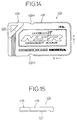
- a noncontact IC card (storage means) 436, a pair of receiving generator coils 438 corresponding to the transmitting generator coil 418 (rewriting means) of the control unit 388, and transmitting communication coils 440 corresponding to the receiving communication coil 420 are mounted on the surface of the case 428. As shown in Fig. 15, a recess 441 is formed in the back surface of the case 428 to avoid the direct sliding contact of the back surface with other members.
- the locking plate 411a engages with the notch 434a to restrain the key card 424 from movement in the direction indicated by the arrow B (Fig. 14), and the locking plate 411b engages with the notch 434b to bias the key card 424 in the direction indicated by the arrow A.
- the key card 424 is moved forcibly in a direction opposite the direction indicated by the arrow A against the resilience of the locking plate 411b to disengage the notch 434a and the locking plate 411a, and then the key card 424 is pulled in the direction indicated by the arrow B.
- Figs. 16 and 17 shows the configuration of the vehicle controller 386
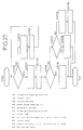
- Fig. 18 is a circuit diagram of the vehicle controller 386.
- the vehicle controller 386 has a CPU 450 provided with an EEPROM 452 for storing characteristic data including an identification number, and data provided by the odometer and the trip meter.
- Connected to the CPU 450 are an ignition coil 454, an oil pump solenoid 456, a pair of carburetor solenoids 458, an exhaust servomotor 460, a throttle opening sensor 462, a crank angle detector 464, an oil level switch 466, a neutral switch 468, a side stand switch 470, a traveling speed sensor 478, a temperature sensor 480, and a main relay 482 connected to loads other than the engine control system.
- Fuses 485a, 485b and 485c are connected to the main relay 482. In case the battery 484 has exhausted, a spare fuse is placed in an idle fuse hole 483 to connect an ACG electrically to the solenoid 328.
- the kick starter is activated with the ACG electrically connected to the solenoid 328, the output current of the ACG is supplied to VBAT and the solenoid 328 to start the engine.
- a V-type two-cylinder engine not shown, provided with spark plugs 455 is disposed under the fuel tank 554, an ignition coil is connected to the spark plugs 455.
- Carburetors 488 are disposed behind the engine, the throttle sensor 462 is combined with the carburetors 488, and the carburetor solenoids 458 for controlling the flow of air through the carburetors 488 are disposed under the fuel tank 554 and near the carburetors 488.
- An ac generator 562 is connected to the left end of the crankshaft of the engine, and the crank angle detector 464 is disposed near the outer circumference of the ac generator 562.
- a traveling speed sensor 478 is disposed near the left end of the countershaft of the engine, and the neutral switch 468 is disposed below the countershaft.
- the side stand switch 470 is combined with the side stand 564.
- a regulating rectifier 566 and the battery 484 are disposed behind the carburetors 488 and under the seat 556.
- a fuse box 568 is connected to the battery 484.
- the temperature sensor 480 for sensing the temperature of the cooling water is disposed above the engine.
- the servomotor 460 for driving a valve for controlling exhaust timing is disposed near the temperature sensor 480 and the steering bar locking unit 316.
- the carburetor solenoids 458 are connected to the battery 484 and regulates the flow of air flowing through an air cleaner 486 into the carburetors 488 to feed an ideal air-fuel mixture from the carburetors 488 to the engine.
- the CPU 450 receives a pulse signal representing engine speed from the crank angle detector 464, the output voltage of the throttle sensor 462 representing an opening of the throttle valve, and a pulse signal representing the rotating speed of the countershaft from the traveling speed sensor 478, and determines the reduction ratio on the basis of the engine speed and the rotating speed of the countershaft.
- the CPU 450 is provided with a program map specifying the mode of operation of the carburetor solenoids 458 corresponding to the reduction ratio.
- the CPU 450 controls the carburetor solenoids 458 according to the traveling speed, the opening of the throttle valve and the engine speed on the basis of the program map so that an optimum air-fuel mixture suitable for the current traveling mode is supplied to the engine.
- each carburetor 488 has a throttle valve 492 disposed with its axis extended perpendicularly to an intake air passage 490.
- the throttle valve 492 is connected by a linkage 494 to a throttle shaft 496.
- the throttle shaft 496 extends through both the carburetors 488.
- the carburetors 488 are fastened together with bolts 489 and a knock pin 491 is attached to the throttle shaft 496 at the junction of the carburetors 488.
- the throttle shaft 496 is turned by means of a throttle pulley 498 and a throttle cable 500.
- Each throttle valve 492 is provided at its one end with a jet needle 502, and a main jet 504 and a slow jet 506 are formed near the needle jet 502 as shown in Fig. 20.
- the ignition time is determined according to throttle opening (%), engine speed (rpm) and reduction ratio. Ignition timing characteristic diagram for the front bank of the engine is shown in Fig. 22 by way of example.
- the traveling speed sensor 478 has a sensor shaft 520 that rotates together with the countershaft, not shown, connected to a joint 518.
- the sensor shaft 520 is supported for rotation on a housing 524 and a thrust washer 522 is put on the inner end of the sensor shaft 520.
- the sensor shaft 520 is provided integrally with two gears 526a and 526b.
- a Hall IC 528 and a rare earth metal magnet 530 are disposed opposite to the gear 526b within the housing 524, and a yoke 532 is combined with the rare earth metal magnet 530.
- the housing 524 is provided with mounting holes 534, and a coupler 536 for connecting the housing 524 electrically to the CPU 450 is fixedly attached to the housing 524.
- the spring 421 is bent elastically to close the key card detecting switch 472, whereby the control unit is connected to the power supply. Then, a current flows through the transmitting generator coil 418 of the main control unit 388 to generate magnetic force and the receiving generator coil 438 of the key card 424 generates electric power. Then, the control data including the identification number stored beforehand in the IC card 436 are converted into currents by the power generated by the receiving generator coil 438 and the transmitting communication coils 440 send the current representing the control data through the receiving communication coil 420 of the main control unit 388 to the CPU 450.
- step S1 When it is decided by the CPU 450 in step S1 that the proper key card 424 is inserted in the main control unit 388, the CPU 450 makes a circuit to supply power to the solenoid 328 of the steering bar locking unit 316 and establishes a CDI (capacitive discharge ignition) enable state. Then, in step S2, the main relay 482 is actuated, and then a query is made in step S3 to see if an ON-state detecting switch 274 is closed. When it is decided that the On-state switch is closed, namely, when the steering bar locking mechanism is disengaged, the procedure goes through step S4 to step S5 to energize the solenoid 328 for 100 msec to make sure that the steering bar is unlocked. Then, in step S6, all the indications on the multifunction display 410 (LCD) of the indicator unit 390 of the vehicle controller 386 are canceled.
- LCD multifunction display 410
- step S3 If it is decided in step S3 that the steering bar locking mechanism is not disengaged, the solenoid 328 is energized in step S7, and then a message, "LOCK" is displayed on the LCD of the indicator unit 390 in step S8.
- the energization of the solenoid 328 for 100 msec and the interruption of energization of the solenoid 328 for 200 msec are repeated alternately to make the solenoid 328 generate a continuous working sound, which informs the user of incomplete disengagement of the steering bar locking mechanism.
- step S9 When it is decided in step S9 that the solenoid 328 has been energized for 10 s or longer and it is decided in step S10 that the ON-state detecting switch 474 is not closed, current supply to the solenoid 328 is stopped in step S11, the warning indicator 404 is turned on to display a warning, "LOCK" in step S12.
- the ON-state detecting switch 474 is turned on when the solenoid 328 is energized for a time less than 10 s, namely, the response to the query in step S10 is affirmative, the solenoid 328 is de-energized in step S13 and all the indications displayed on the LCD of the indicator unit 390 are turned off in step S14.
- the cam section 362 of the rotating member 362 comes into engagement with the projection 380 of the retaining member 326 and turns the retaining member 326 in the direction indicated by the arrow D. Consequently, the retaining projection 378 of the retaining member 326 engages with the second tooth 360 of the rotating member 324 to retain the rotating member 324.
- the rotating member 324 is turned from the first position (ON position) to the second position (OFF position). Then, the locking member 322 and the sliding member 344 are moved from a position shown in Fig. 6C away from the stem pipe 318 to a position shown in Fig.
- the solenoid 328 is energize further for a predetermined time to turn the retaining member 326 in the direction opposite the direction indicated by the arrow D so that the projection 378 is disengaged from the second tooth 360.
- the rotating member 324 is turned further in the direction indicated by the arrow B to a position shown in Fig. 6A.
- the operating lever is turned further in the direction indicated by the arrow F through the cable 372, whereby the starter is actuated to start the engine.
- the traveling speed of the motorcycle 300 is displayed on the multifunction display 410 of the indicator unit 390.
- the push button of the function switch 408 is pushed repeatedly, travel distance, trip distance and the temperature of the cooling water are displayed by turns below the indication of the traveling speed. Since a traveling pulse counter over flows when the traveling speed is 7 km/h or below, the traveling speed is estimated on the basis of the frequency of overflow and the estimated traveling speed is displayed. If any traveling speed pulse is not generated for 0.5 sec or longer, an indication, "0 km/h" is displayed automatically.
- the traveling speed is displayed at intervals of 0.1 sec when the traveling speed is below 9 km/h, and at intervals of 0.5 sec when the traveling speed is 9 km/h or above to avoid the flickering of the ten's place.
- the indication of the temperature of the cooling water flickers and the warning indicator 404 is turned on.
- the travel distance is recorded in the unit of 1 km on the EEPROM 452.
- the EEPROM 452 records a distance less than 1 km in the unit of 0.1 km.
- the total travel distance is recorded at three positions in each bank every time the total distance increases 1 km, the bank shifts every 1 km from a bank 1 to a bank 5 sequentially, and returns from the bank 5 to the bank 1.
- each bank the central value among the three data is determined by majority rule. If the three data are different from each other, the value of the data of the bank is indefinite. Theoretically, the difference between the central values of the adjacent banks must be 1 km. Actually, the maximum bank value differing by 1 km from the second maximum bank value is selected as the total travel distance. After the total travel distance has been determined, integration of cumulative data less than 1 km recorded at other addresses is started. When any maximum bank value is determined, it is decided that the total travel distance is indefinite and an indication, "...km” is displayed and the warning indicator 404 is turned on.
- the trip distance is reset by the following procedure. As shown in Fig. 26, the current trip distance is displayed on the multifunction display 410 after the push button of the function switch 408 has been continuously pressed for 1.5 sec, the trip distance is reset to 0 km when the push button of the function switch 408 is pressed further for 0.5 sec (2.0 sec in total), and then the measurement of trip distance is started when the push button of the function switch 408 is released. If the push button of the function switch 408 is released in a time in the range of 1.5 sec to 2.0 sec, the current trip distance is displayed.
- the multifunction display 410 has a plurality of warning functions; an indication, "OIL” is displayed when the quantity of the oil decreases below a predetermined value, an indication, “CARD” is displayed when the key card 424 is about to come off the main control unit 388 while the motorcycle 300 is traveling, an indication, “SPEED” is displayed when the traveling speed exceeds 85 km/h, an indication, “OFF” is displayed when a kill switch is turned off, an indication, “Err. 1” is displayed when the input voltage of the control unit is higher than a predetermined voltage, an indication, “Err. 2” is displayed when the exhaust valve is locked, and an indication, “Err. 3” is displayed when the throttle sensor 462 malfunctions.
- an indication, "OIL” is displayed when the quantity of the oil decreases below a predetermined value
- an indication, "CARD” is displayed when the key card 424 is about to come off the main control unit 388 while the motorcycle 300 is traveling
- an indication, “SPEED” is displayed when the traveling speed exceeds
- the corresponding warnings are displayed alternately or by turns, and a travel distance at the start of displaying the warnings and a trip distance from the start of displaying the warnings are recorded on the EEPROM 452.
- This travel distance and the trip distance are displayed on the multifunction display 410 when the push button of the function switch is operated.
- an indication, "---C" is displayed.
- a control procedure represented by a flow chart shown in Fig. 27 is carried out to prevent locking the steering bar while the motorcycle 300 is traveling and to prevent the key card 424 from coming off the main control unit 388.
- a query is made instep S20 to see if the ON-state detecting switch 474 is closed. If the response in step S20 is negative, the warning, "LOCK” is given in step S21 and then the solenoid 328 is energized in step S22. If the ON-state detecting switch 474 is closed, namely, if the response in step S20 is affirmative, the warning, "LOCK” is canceled in step S23 and the solenoid 328 is de-energized in step S24.
- step S25 A query is made in step S25 to see if the key card detecting switch 472 is closed. If the response in step S25 is affirmative, the warning, "CARD” is canceled in step S26. If the response in step S25 is negative, a query is made in step S27 to see if the traveling speed is 1 km/h or higher. If the response in step S27 is affirmative, the warning, "CARD” is given in step S28. When the traveling speed is below 1 km/h, namely, the motorcycle 300 is stopped, and then the trip distance and the total travel distance is written on the EEPROM 452 in step S29 and the main relay 482 is turned off in step S30.
- the operating lever 385 is turned in a direction opposite the direction indicated by the arrow F to reduce the engine speed after the motorcycle 300 has reached the destination and the motorcycle 300 has been stopped. Consequently, the cable 372 pulls the rotating member 324 to turn the rotating member 324 in the direction indicated by the arrow A (Fig. 4) against the resilience of the spring 325, consequently, the retaining projection 378 is brought into engagement with the second tooth 360 to retain the rotating member at the OFF position as shown in Fig. 6B, so that the ignition circuit is opened to stop the engine.
- the steering bar 317 is turned fully in a predetermined direction, for example, counterclockwise, and the operating lever 385 is turned further in the direction opposite the direction indicated by the arrow F to lock the steering bar 317.
- the cable 372 turns the rotating member 324 in the direction indicated by the arrow A, the retaining projection 378 is brought into engagement with the first tooth 358, so that the locking member 322 comes into engagement with the step pipe 318 to lock the stem pipe 318 as shown in Fig. 6C.
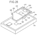
- a special racing key card 600 not provided with any key member as shown in Fig. 28 is used when the motorcycle 300 is entered in a race.
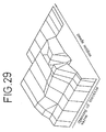
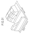
- the racing key card 600 is provided with an IC card 602 storing control data for controlling the motorcycle 300 in a racing mode; that is map data concerning the ignition timing characteristic for the front cylinder as shown in Fig. 29, an ignition timing characteristic for the rear cylinder as shown in Fig. 30, an opening characteristic for the RC valve as shown in Fig. 31, and a carburetor solenoid characteristic as shown in Fig. 32 is stored in the IC card 602.
- the temperature of the cooling water is displayed on the multifunction display 410 instead of the traveling speed and a program number is displayed below the temperature.
- Also stored in the IC card 602 are data for preventing alteration, the data of past record and the data for speed warning.
- the racing key card 600 is effective only when the oil level switch 466, the neutral switch 468 and the side stand switch 470 are grounded. Record of the use of the racing key card 600 is stored in the EEPROM 452, and the record can be displayed on the multifunction display 410 by operating the push button of the multifunction switch 408. Fixed values, the sum of which is a fixed value, are placed at the ends of the control data.
- the CPU 450 examines the sum of the fixed values to see if the control data are proper ones, i.e, if the racing key card 600 is a proper one. Once it is determined that the control data are proper and the control data are loaded into the CPU 450, the CPU 450 examines only the sum of the fixed values or the program number of the racing key card 600 for the next and the following occasions for using the racing key card 600.
- the motor cycle 300 can be controlled for ordinary touring or for racing simply by selectively using the key card 424 or the racing key card 600.
- the vehicle controller has a simple configuration and is capable of dealing with different modes of operation of the motorcycle.
- the electric system of the vehicle is connected to the power supply and all the control data previously stored in the engine control unit is replaced with the control data stored in the storage means of the key card when the key card is loaded into the engine control unit. Accordingly, the control data can be optionally and readily changed according to a desired mode of operation of the vehicle
- Fig. 1 is a perspective view of an essential portion of a motorcycle incorporating a vehicle controller in a preferred embodiment according to the present invention.
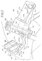
- Fig. 2 is a fragmentary side view of the motorcycle.
- Fig. 3 is a partly sectional plan view of a steering bar locking unit included in the vehicle controller and combined with the head frame of the motorcycle.
- Fig. 4 is a plan view of the steering bar locking unit, in which a cover is removed.
- Fig. 5 is a longitudinal sectional view of the steering bar locking unit.
- Figs. 6A, 6B and 6C are plan views of the steering bar locking unit placed in an ON position, an OFF position and a locking position, respectively.
- Fig. 7 is a perspective view of a combination of a stay and a sty bar for holding the vehicle controller.
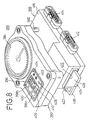
- Fig. 8 is a perspective view of the vehicle controller.
- Fig. 9 is a plan view of a main control unit included in the vehicle controller.
- Fig. 10 is a front view of the main control unit.
- Fig. 11 is a schematic plan view of the main control unit.
- Fig. 12 is a sectional view taken on line XII-XII in Fig. 11.
- Fig. 13 is a schematic perspective view of the vehicle controller and a key card.
- Fig. 14 is a plan view of the key card.
- Fig. 15 is a front view of the key card.
- Fig. 16 is a perspective view of the motorcycle, showing the arrangement of components.
- Fig. 17 is a diagrammatic view of the controller of the vehicle controller.
- Fig. 18 is a circuit diagram of the electric system of the controller.
- Fig. 19 is a block diagram of a control circuit included in the controller, for controlling a carburetor solenoid.
- Fig. 20 is a longitudinal sectional view of a carburetor.
- Fig. 21 is a sectional view of the carburetor.
- Fig. 22 is a graph showing ignition timing characteristic in connection with the opening of the throttle valve, engine speed and ignition timing.
- Fig. 23 is a longitudinal sectional view of a traveling speed sensor.
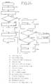
- Fig. 24 is a flow chart of a control procedure for controlling the solenoid of a steering bar locking unit.
- Fig. 25 is a diagrammatic view of assistance in explaining banks for controlling recording of total travel distance.
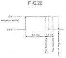
- Fig. 26 is a diagram of assistance in explaining a procedure for resetting trip distance.
- Fig. 27 is a flow chart of a procedure for locking the steering bar and detecting the condition of the key card.
- Fig. 28 is a schematic perspective view of the controller and a racing key card.
- Fig. 29 is a graph of assistance in explaining an ignition timing characteristic for timing the ignition of the front cylinder of an engine.
- Fig. 30 is a graph of assistance in explaining an ignition timing characteristic for timing the ignition of the rear cylinder of the engine.
- Fig. 31 is a graph of assistance in explaining an RC valve opening characteristic.
- Fig. 32 is graph of assistance in explaining the characteristic of a carburetor solenoid.
- Fig. 33 is a plan view of assistance in explaining indications on a multifunction display in a racing mode.
Abstract
Description
- The present invention relates to a vehicle controller comprising an engine control unit provided with an electric circuit for starting and stopping the engine of a vehicle, and a key for controlling the operation of the engine in cooperation with the engine control unit.
- A mechanical ignition key is used for starting and stopping the engine of, for example, a motorcycle. When the engine is started by means of an engine starting arrangement that is operated with such a mechanical ignition key, it is possible to start the engine unduly without using the ignition key. An expensive, complicated, preventive arrangement is necessary for preventing undue starting of the engine. Accordingly, the computerized control of starting and stopping of the engine has been desired in recent years.
- Incidentally, ignition timing for timing the ignition system of an engine is varied according to the condition and the service condition of the engine and, therefore, data for the computerized control of ignition timing stored in a ROM must be changed.
- An apparatus disclosed in Japanese Patent Laid-open (Kokai) No. 2-191870 stores adjusting data for changing parameters for timing ignition in a data storage means, changes the adjusting data stored in the data storage means for new adjusting data transmitted to the data storage means according to instructions given by a communicating means.
- However, this known apparatus simply rewrites the adjusting data for changing the parameters for determining the ignition time and hence the data can be changed in very narrow ranges. Consequently, the apparatus is unable to change the vehicle control data optionally and has difficulty in effectively responding to user's requests varying in wide ranges.
- The present invention has been made to solve such problems and it is therefore an object of the present invention to provide a controller for a vehicle, capable of simply and surely changing control data necessary for the operation of an engine control unit for starting and stopping the engine.
- With the foregoing object in view, the present invention provides an engine controller comprising:
an engine control unit provided with an electric circuit for starting and stopping the engine of a vehicle mounted on the body frame of the vehicle; and
a key card that controls the operation of the engine in cooperation with the engine control unit;
characterized in that the key card comprises;
a storage means capable of storing all the data necessary for the operation of the engine control unit, and
a data rewriting means for destroying all the control data stored beforehand in the engine control unit and writing the control data stored in the storage means on the engine control unit. - In the controller for a vehicle in accordance with the present invention, the power supply of the vehicle is turned on and all the control data stored beforehand in the engine control unit is changed for the control data stored in the storage means of the key card when the key card is loaded into the engine control unit. Accordingly, the control data can be optionally and easily changed according to user's requests.
- A vehicle controller in a preferred embodiment according to the present invention will be described hereinafter with reference to the accompanying drawings.
- Figs. 1 and 2 are fragmentary views of a
motorcycle 300 incorporating a vehicle controller in a preferred embodiment according to the present invention. Themotorcycle 300 has abody frame 302. Thebody frame 302 has ahead frame 304 transversely expanding toward the rear as shown in Fig. 3. Thehead frame 304 defines achamber 306 opening toward the rear. - As shown in Fig. 3, the
head frame 304 has ahole 308 opening into the front portion of thechamber 306, and is provided in its rear end withbrackets holes Main frames 314a and 314b extend backward from the opposite sides of the rear end of thehead frame 304. - As shown in Fig. 1, a
steering bar 317 is joined to the upper end of afront fork 540, afront fender 542 is fastened to the lower portion of thefront fork 540, and a front wheel is held for rotation on the lower end of thefront fork 540. The front side of thesteering bar 317 is covered with afairing 546. Aheadlight 548,rearview mirrors 550 and ascreen 552 are held on thefairing 546. Afuel tank 554 is mounted on themain frames 314a and 314b, and aseat 556 is disposed behind thefuel tank 554. In Fig. 1, indicated at 558 is a top bridge disposed on the side of thesteering bar 317. - A steering
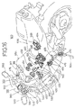
bar locking unit 316 is placed within thechamber 306 of thehead frame 304. The steeringbar locking unit 316 has ahousing 320 held in thechamber 304 of thehead frame 304 so as to receive astem pipe 318 that turns together with thesteering bar 317. Contained in thehousing 320 are a steeringbar locking member 322 capable of being moved between a locking position where thelocking member 322 engages thestem pipe 318 to lock thesteering bar 317 and a releasing position where thelocking member 322 releases thestem pipe 318 to allow thesteering bar 317 to turn, a rotatingmember 324 that is turned in the direction of the arrow A (Fig. 4) to shift thelocking member 322 from the releasing position to the locking position, and adriving device 323 for turning the rotatingmember 324 in angular steps through a first position (ON position shown in Fig. 6A) to allow thesteering bar 317 to turn and the engine to operate, a second position (OFF position shown in Fig. 6B) to allow thesteering bar 317 to turn and to inhibit the engine from operating, and a third position (locking position shown in Fig. 6C) to lock thesteering bar 317. - As shown in Figs. 4 and 5, the
driving device 323 comprises aspring 325 for biasing the rotatingmember 324 in the direction indicated by the arrow B opposite the direction indicated by the arrow A, aretaining member 326 for retaining the rotatingmember 324 at a predetermined angular position, and asolenoid 328 that is actuated when a starter switch is closed to disengage the retainingmember 326 from the rotatingmember 324 to enable the rotatingmember 324 to be turned stepwise from the first position through the second position to the third position. - The
housing 320 has acase 330, aninner lid 332 and acover 334. Thehousing 320 is provided with athrough hole 336 for receiving thestem pipe 318. Apin 338 to be fitted in ahole 308 formed in thehead pipe 304 projects from the front end of thecase 330.Projections case 330 at positions respectively corresponding to thebrackets head frame 304, andholes projections holes pin 338 fitted in thehole 308,bolts holes 432a and 342b and screwed in the threadedholes housing 320 to thehead frame 304. - As shown in Fig. 4, the
cylindrical locking member 322 is fixed to one end of a slidingmember 344 capable of moving in directions indicated by the arrowsC. A slot 346 is formed in the other end of thesliding member 344, afixed lug 348 formed within thehousing 320 is received in theslot 346, and aspring 350 is extended between the fixedlug 348 and the end wall of theslot 346. Arectangular guide slot 352 is formed in the substantially middle portion of the slidingmember 344. - The rotating
member 324 is supported pivotally on apin 354 within thehousing 320. Aneccentric pin 356 projecting from the periphery of the rotatingmember 324 is received in theguide slot 352 of the slidingmember 344. The rotatingmember 324 is provided in its circumference with afirst tooth 358 with which the retainingmember 326 engages to hold the rotatingmember 324 at the third position (locking position), asecond tooth 360 with which the retainingmember 326 engages to hold the rotatingmember 324 at the second position (OFF position), and acam section 362 separated a predetermined angular distance in the direction of the arrow B from thefirst tooth 358. - One end of the
spring 325 is connected to the rotatingmember 324 at a position in the periphery substantially diametrically opposite theeccentric pin 356. Acable 372 has one end connected to the rotatingmember 324 and the other end connected to an operating member, which will be described later, extending outside from the housing 320 (Fig. 1)
The retainingmember 326 is supported pivotally on apin 374 fixedly disposed within thehousing 320 and is biased in the direction of the arrow D (Fig. 4) with aspring 376 mounted on thepin 374. Theretaining member 326 has aretaining projection 378 and aprojection 380, which project toward the rotatingmember 324. Theretaining projection 378 is able to engage with thefirst tooth 358 and thesecond tooth 360. Theprojection 380 and thecam section 362 constitute aholding mechanism 379 for holding the rotatingmember 326 at the second position (OFF position). Ahole 381 opening into a slit is formed in the extremity of theretaining member 326, the extremity of a plunger projecting from thesolenoid 328 is passed through thehole 381 and the expandedend 383 is in engagement with the extremity of theretaining member 326. - As shown in Fig. 1, an
operating lever 385 is supported pivotally in parallel to achoke lever 560 on thehead frame 304 at a position under the steeringbar locking unit 316. The other end of thecable 372 connected to the rotatingmember 324 of the steeringbar locking unit 316 is connected to theoperating lever 385. When the rotatingmember 324 is turned, theoperating lever 385 is turned through a first position, a second position and a third position. As shown in Fig. 1, a first portion of thecable 372 connected to the rotatingmember 324 and a second portion of thecable 372 connected to theoperating lever 385 are connected by a connectingdevice 371. The connectingdevice 371 is disengaged to separate the first and the second portion of thecable 372 to enable individual maintenance on the steeringbar locking unit 316 and theoperating lever 385. - As shown in Fig. 2, a
vehicle controller 386 in a third embodiment according to the present invention is held by a pair of holdingmembers 384 on astay 382 extending toward the front from thehead frame 304. Astay bar 200 is fixed to thestay 382 so as to extend transversely. As shown in Fig. 7, thestay bar 200 is provided at positions near the opposite ends thereof withfastening holes bolts 204 for fastening thevehicle controller 386 thereto.Bolts 204 inserted through thefastening holes member 384 holding themain control unit 388 of thevehicle controller 386 to fasten themain control unit 388 to thestay bar 200. Eachbolt 204 is a socket head bolt having a head provided with asocket 206 having a special shape to prevent thebolt 204 from being easily unfastened. - The
stay 382 is provided withprotrusions stay bar 200 to prevent the dislocation of thevehicle controller 386, and aprotrusion 211 behind theprotrusion 210 to preventcouplers 413a and 413b, which will be described later, from falling off. Thus, thevehicle controller 386 cannot be easily removed and the removal of thecouplers 413a and 413b is prevented. - As shown in Fig. 8, the
vehicle controller 386 comprises themain control unit 388 and anindicator unit 390. Theindicator unit 390 is supported onposts 392 projecting upward from themain control unit 388 and has a first indicator (analog tachometer for indicating the engine speed of the engine) 394, and a second indicator (digital indicator) 396. Thesecond indicator 396 is provided withdirection indicators beam indicator 400, aside stand indicator 402, awarning indicator 404, aneutral indicator 406, and amultifunction display 410 serving as a speedometer and to be operated by afunction switch 408 to display travel distance, trip distance, cooling water temperature and warnings by turns. - When a
key card 424 is inserted in themain control unit 388 through aslot 422 formed in themain control unit 388 with the push button of thefunction switch 408 depressed and the push button of thefunction switch 408 is released after inserting thekey card 424 into themain control unit 388, a number is displayed on themultifunction display 410. The number can be incremented by depressing the push button of thefunction switch 408. The displayed number can be set by depressing the push button of thefunction switch 408 continuously for ten seconds. This operation is performed for four digits to set a four-digit identification number. The power supply of the motorcycle can be turned on by entering the identification number in case thekey card 424 is lost. When "0000" is registered, the resetting of the identification number is impossible. If wrong identification numbers are entered three times to start the engine, password protection cannot be called of unless the properkey card 424 is inserted in themain control unit 388. - Figs. 9 and 10 are a plan view and a front view, respectively, of the
main control unit 388, Fig. 11 is a schematic plan view of themain control unit 388, showinglocking plates 411a and 411b included in themain control unit 388 to restrain thekey card 424 from falling off themain control unit 388 and Fig. 12 is a sectional view taken on line XII-XII in Fig. 11. Themain control unit 388 has acasing 416 provided withconnectors couplers 413a and 413b are connected to connect a power line connected to a battery, and signal lines to themain control unit 388. Atransmitting generator coil 418 and a receivingcommunication coil 420 are contained within thecasing 416 and are connected by acable 417 to a CPU, which will be described later (Figs. 12 and 13). Theslot 422 is formed in one side wall of thecasing 416. Thekey card 424 having the shape of a flat plate can be inserted into and extracted from thecasing 416 through theslot 422. When thekey card 422 is inserted through theslot 422 into thecasing 416, aspring 421 is bent elastically to close a key card detecting switch 472 (Fig. 11). - As shown in Fig. 8, a holding
projection 423 projects from one end of theslot 422 to prevent akey member 426 from coming off thekey card 424 inserted in theslot 422. As shown in Fig. 9, themain control unit 388 is provided with awindow 425 to enable the visual recognition of thekey card 424 inserted in themain control unit 388. Adhesion of dust and foreign matters to thekey card 424 can be easily recognized through thewindow 425. As shown in Fig. 10, anopening 427 is formed opposite to theslot 422. Dust and the like adhering to the surface of a card reader can be pushed out through theopening 427 by inserting thekey card 424 through theslot 422 into themain control unit 388. - Referring to Figs. 13 to 15, the
key card 424 comprises the aforesaidkey member 426, and a substantially flat case (body) 428. One corner of thecase 428 is cut to form akey receiving opening 430, and thekey member 426 is inserted in thekey receiving opening 430. A pair of lockingplates 432 are disposed near thekey receiving opening 430 to restrain thekey member 426 inserted in the key receiving opening 430 from slipping out of thekey receiving opening 430.Notches case 428. A noncontact IC card (storage means) 436, a pair of receivinggenerator coils 438 corresponding to the transmitting generator coil 418 (rewriting means) of thecontrol unit 388, and transmittingcommunication coils 440 corresponding to the receivingcommunication coil 420 are mounted on the surface of thecase 428. As shown in Fig. 15, arecess 441 is formed in the back surface of thecase 428 to avoid the direct sliding contact of the back surface with other members. - As shown in Figs. 11 and 14, the
locking plate 411a engages with thenotch 434a to restrain thekey card 424 from movement in the direction indicated by the arrow B (Fig. 14), and the locking plate 411b engages with thenotch 434b to bias thekey card 424 in the direction indicated by the arrow A. When extracting thekey card 424 through theslot 422, first thekey card 424 is moved forcibly in a direction opposite the direction indicated by the arrow A against the resilience of the locking plate 411b to disengage thenotch 434a and thelocking plate 411a, and then thekey card 424 is pulled in the direction indicated by the arrow B. - Figs. 16 and 17 shows the configuration of the
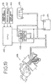
vehicle controller 386, and Fig. 18 is a circuit diagram of thevehicle controller 386. Thevehicle controller 386 has aCPU 450 provided with anEEPROM 452 for storing characteristic data including an identification number, and data provided by the odometer and the trip meter. Connected to theCPU 450 are anignition coil 454, anoil pump solenoid 456, a pair ofcarburetor solenoids 458, anexhaust servomotor 460, athrottle opening sensor 462, acrank angle detector 464, anoil level switch 466, aneutral switch 468, aside stand switch 470, a travelingspeed sensor 478, atemperature sensor 480, and amain relay 482 connected to loads other than the engine control system.Fuses main relay 482. In case thebattery 484 has exhausted, a spare fuse is placed in anidle fuse hole 483 to connect an ACG electrically to thesolenoid 328. When the kick starter is activated with the ACG electrically connected to thesolenoid 328, the output current of the ACG is supplied to VBAT and thesolenoid 328 to start the engine. - Referring to Fig. 16, a V-type two-cylinder engine, not shown, provided with
spark plugs 455 is disposed under thefuel tank 554, an ignition coil is connected to the spark plugs 455.Carburetors 488 are disposed behind the engine, thethrottle sensor 462 is combined with thecarburetors 488, and thecarburetor solenoids 458 for controlling the flow of air through thecarburetors 488 are disposed under thefuel tank 554 and near thecarburetors 488. - An
ac generator 562 is connected to the left end of the crankshaft of the engine, and thecrank angle detector 464 is disposed near the outer circumference of theac generator 562. A travelingspeed sensor 478 is disposed near the left end of the countershaft of the engine, and theneutral switch 468 is disposed below the countershaft. The side standswitch 470 is combined with theside stand 564. A regulatingrectifier 566 and thebattery 484 are disposed behind thecarburetors 488 and under theseat 556. Afuse box 568 is connected to thebattery 484. - The
temperature sensor 480 for sensing the temperature of the cooling water is disposed above the engine. Theservomotor 460 for driving a valve for controlling exhaust timing is disposed near thetemperature sensor 480 and the steeringbar locking unit 316. - As shown in Fig. 19, the
carburetor solenoids 458 are connected to thebattery 484 and regulates the flow of air flowing through anair cleaner 486 into thecarburetors 488 to feed an ideal air-fuel mixture from thecarburetors 488 to the engine. TheCPU 450 receives a pulse signal representing engine speed from thecrank angle detector 464, the output voltage of thethrottle sensor 462 representing an opening of the throttle valve, and a pulse signal representing the rotating speed of the countershaft from the travelingspeed sensor 478, and determines the reduction ratio on the basis of the engine speed and the rotating speed of the countershaft. TheCPU 450 is provided with a program map specifying the mode of operation of thecarburetor solenoids 458 corresponding to the reduction ratio. TheCPU 450 controls thecarburetor solenoids 458 according to the traveling speed, the opening of the throttle valve and the engine speed on the basis of the program map so that an optimum air-fuel mixture suitable for the current traveling mode is supplied to the engine. - As shown in Fig. 20, each
carburetor 488 has athrottle valve 492 disposed with its axis extended perpendicularly to anintake air passage 490. Thethrottle valve 492 is connected by alinkage 494 to athrottle shaft 496. As shown in Fig. 21, thethrottle shaft 496 extends through both thecarburetors 488. Thecarburetors 488 are fastened together withbolts 489 and aknock pin 491 is attached to thethrottle shaft 496 at the junction of thecarburetors 488. - The
throttle shaft 496 is turned by means of athrottle pulley 498 and athrottle cable 500. Eachthrottle valve 492 is provided at its one end with ajet needle 502, and amain jet 504 and aslow jet 506 are formed near theneedle jet 502 as shown in Fig. 20. - The ignition time is determined according to throttle opening (%), engine speed (rpm) and reduction ratio. Ignition timing characteristic diagram for the front bank of the engine is shown in Fig. 22 by way of example.
- As shown in Fig. 23, the traveling
speed sensor 478 has asensor shaft 520 that rotates together with the countershaft, not shown, connected to a joint 518. Thesensor shaft 520 is supported for rotation on ahousing 524 and athrust washer 522 is put on the inner end of thesensor shaft 520. Thesensor shaft 520 is provided integrally with twogears Hall IC 528 and a rareearth metal magnet 530 are disposed opposite to thegear 526b within thehousing 524, and ayoke 532 is combined with the rareearth metal magnet 530. Magnetic flux acting on the Hall element of theHall IC 528 varies as thesensor shaft 520 rotates, the Hall IC converts the output voltage signal of the Hall element into a rectangular pulse signal varying between 0 V and 5 V, and gives the rectangular pulse signal to theCPU 450. Thehousing 524 is provided with mountingholes 534, and acoupler 536 for connecting thehousing 524 electrically to theCPU 450 is fixedly attached to thehousing 524. - The operation of the vehicle controller thus constructed will be described hereinafter with reference to Fig. 24 in connection with that of the
motorcycle 300. - When the
key card 424 is inserted through theslot 422 into themain control unit 388 of thevehicle controller 386, thespring 421 is bent elastically to close the keycard detecting switch 472, whereby the control unit is connected to the power supply. Then, a current flows through thetransmitting generator coil 418 of themain control unit 388 to generate magnetic force and thereceiving generator coil 438 of thekey card 424 generates electric power. Then, the control data including the identification number stored beforehand in theIC card 436 are converted into currents by the power generated by thereceiving generator coil 438 and the transmittingcommunication coils 440 send the current representing the control data through the receivingcommunication coil 420 of themain control unit 388 to theCPU 450. - When it is decided by the
CPU 450 in step S1 that the properkey card 424 is inserted in themain control unit 388, theCPU 450 makes a circuit to supply power to thesolenoid 328 of the steeringbar locking unit 316 and establishes a CDI (capacitive discharge ignition) enable state. Then, in step S2, themain relay 482 is actuated, and then a query is made in step S3 to see if an ON-state detecting switch 274 is closed. When it is decided that the On-state switch is closed, namely, when the steering bar locking mechanism is disengaged, the procedure goes through step S4 to step S5 to energize thesolenoid 328 for 100 msec to make sure that the steering bar is unlocked. Then, in step S6, all the indications on the multifunction display 410 (LCD) of theindicator unit 390 of thevehicle controller 386 are canceled. - If it is decided in step S3 that the steering bar locking mechanism is not disengaged, the
solenoid 328 is energized in step S7, and then a message, "LOCK" is displayed on the LCD of theindicator unit 390 in step S8. The energization of thesolenoid 328 for 100 msec and the interruption of energization of thesolenoid 328 for 200 msec are repeated alternately to make thesolenoid 328 generate a continuous working sound, which informs the user of incomplete disengagement of the steering bar locking mechanism. - When it is decided in step S9 that the
solenoid 328 has been energized for 10 s or longer and it is decided in step S10 that the ON-state detecting switch 474 is not closed, current supply to thesolenoid 328 is stopped in step S11, thewarning indicator 404 is turned on to display a warning, "LOCK" in step S12. When the ON-state detecting switch 474 is turned on when thesolenoid 328 is energized for a time less than 10 s, namely, the response to the query in step S10 is affirmative, thesolenoid 328 is de-energized in step S13 and all the indications displayed on the LCD of theindicator unit 390 are turned off in step S14. - When the proper
key card 424 is inserted in themain control unit 388 and thesolenoid 328 is energized for the predetermined time, the expandedend 383 of the plunger is moved in the direction of the arrow E (Fig. 4). Consequently, the retainingmember 326 is turned against the resilience of the spring 373 in a direction opposite the direction indicated by the arrow D (Fig. 4), the retainingprojection 378 is disengaged from thefirst tooth 358 of the rotatingmember 324, and then the rotatingmember 324 is turned in the direction indicated by the arrow B by thespring 325. - When the rotating
member 324 is turned in the direction indicated by the arrow B through a predetermined angle, thecam section 362 of the rotatingmember 362 comes into engagement with theprojection 380 of the retainingmember 326 and turns the retainingmember 326 in the direction indicated by the arrow D. Consequently, the retainingprojection 378 of the retainingmember 326 engages with thesecond tooth 360 of the rotatingmember 324 to retain the rotatingmember 324. Thus, the rotatingmember 324 is turned from the first position (ON position) to the second position (OFF position). Then, the lockingmember 322 and the slidingmember 344 are moved from a position shown in Fig. 6C away from thestem pipe 318 to a position shown in Fig. 6B under the cooperative guiding action of theeccentric pin 356 of the rotatingmember 324 and theslot 352 of the slidingmember 344 to release thestem pipe 318, so that thesteering bar 317 is able to turn. Meanwhile, the operatinglever 385 connected to the rotatingmember 324 by thecable 372 is turned in the direction indicated by the arrow F (Fig. 2) through a predetermined angle to an OFF position. - Then, the
solenoid 328 is energize further for a predetermined time to turn the retainingmember 326 in the direction opposite the direction indicated by the arrow D so that theprojection 378 is disengaged from thesecond tooth 360. Then, the rotatingmember 324 is turned further in the direction indicated by the arrow B to a position shown in Fig. 6A. Meanwhile, the operating lever is turned further in the direction indicated by the arrow F through thecable 372, whereby the starter is actuated to start the engine. - As shown in Fig. 8, the traveling speed of the
motorcycle 300 is displayed on themultifunction display 410 of theindicator unit 390. When the push button of thefunction switch 408 is pushed repeatedly, travel distance, trip distance and the temperature of the cooling water are displayed by turns below the indication of the traveling speed. Since a traveling pulse counter over flows when the traveling speed is 7 km/h or below, the traveling speed is estimated on the basis of the frequency of overflow and the estimated traveling speed is displayed. If any traveling speed pulse is not generated for 0.5 sec or longer, an indication, "0 km/h" is displayed automatically. The traveling speed is displayed at intervals of 0.1 sec when the traveling speed is below 9 km/h, and at intervals of 0.5 sec when the traveling speed is 9 km/h or above to avoid the flickering of the ten's place. When the temperature of the cooling water exceeds a predetermined temperature, the indication of the temperature of the cooling water flickers and thewarning indicator 404 is turned on. - The travel distance is recorded in the unit of 1 km on the
EEPROM 452. When the power supply is disconnected, theEEPROM 452 records a distance less than 1 km in the unit of 0.1 km. As shown in Fig. 25, the total travel distance is recorded at three positions in each bank every time thetotal distance increases 1 km, the bank shifts every 1 km from abank 1 to abank 5 sequentially, and returns from thebank 5 to thebank 1. - In each bank, the central value among the three data is determined by majority rule. If the three data are different from each other, the value of the data of the bank is indefinite. Theoretically, the difference between the central values of the adjacent banks must be 1 km. Actually, the maximum bank value differing by 1 km from the second maximum bank value is selected as the total travel distance. After the total travel distance has been determined, integration of cumulative data less than 1 km recorded at other addresses is started. When any maximum bank value is determined, it is decided that the total travel distance is indefinite and an indication, "...km" is displayed and the
warning indicator 404 is turned on. - The trip distance is reset by the following procedure. As shown in Fig. 26, the current trip distance is displayed on the
multifunction display 410 after the push button of thefunction switch 408 has been continuously pressed for 1.5 sec, the trip distance is reset to 0 km when the push button of thefunction switch 408 is pressed further for 0.5 sec (2.0 sec in total), and then the measurement of trip distance is started when the push button of thefunction switch 408 is released. If the push button of thefunction switch 408 is released in a time in the range of 1.5 sec to 2.0 sec, the current trip distance is displayed. - The
multifunction display 410 has a plurality of warning functions; an indication, "OIL" is displayed when the quantity of the oil decreases below a predetermined value, an indication, "CARD" is displayed when thekey card 424 is about to come off themain control unit 388 while themotorcycle 300 is traveling, an indication, "SPEED" is displayed when the traveling speed exceeds 85 km/h, an indication, "OFF" is displayed when a kill switch is turned off, an indication, "Err. 1" is displayed when the input voltage of the control unit is higher than a predetermined voltage, an indication, "Err. 2" is displayed when the exhaust valve is locked, and an indication, "Err. 3" is displayed when thethrottle sensor 462 malfunctions. - If those troubles occur simultaneously, the corresponding warnings are displayed alternately or by turns, and a travel distance at the start of displaying the warnings and a trip distance from the start of displaying the warnings are recorded on the
EEPROM 452. This travel distance and the trip distance are displayed on themultifunction display 410 when the push button of the function switch is operated. When the temperature of the cooling water is 35-C or below or when the temperature sensor malfunctions, an indication, "---C" is displayed. - A control procedure represented by a flow chart shown in Fig. 27 is carried out to prevent locking the steering bar while the
motorcycle 300 is traveling and to prevent thekey card 424 from coming off themain control unit 388. A query is made instep S20 to see if the ON-state detecting switch 474 is closed. If the response in step S20 is negative, the warning, "LOCK" is given in step S21 and then thesolenoid 328 is energized in step S22. If the ON-state detecting switch 474 is closed, namely, if the response in step S20 is affirmative, the warning, "LOCK" is canceled in step S23 and thesolenoid 328 is de-energized in step S24. - A query is made in step S25 to see if the key
card detecting switch 472 is closed. If the response in step S25 is affirmative, the warning, "CARD" is canceled in step S26. If the response in step S25 is negative, a query is made in step S27 to see if the traveling speed is 1 km/h or higher. If the response in step S27 is affirmative, the warning, "CARD" is given in step S28. When the traveling speed is below 1 km/h, namely, themotorcycle 300 is stopped, and then the trip distance and the total travel distance is written on theEEPROM 452 in step S29 and themain relay 482 is turned off in step S30. - Incidentally, the operating
lever 385 is turned in a direction opposite the direction indicated by the arrow F to reduce the engine speed after themotorcycle 300 has reached the destination and themotorcycle 300 has been stopped. Consequently, thecable 372 pulls the rotatingmember 324 to turn the rotatingmember 324 in the direction indicated by the arrow A (Fig. 4) against the resilience of thespring 325, consequently, the retainingprojection 378 is brought into engagement with thesecond tooth 360 to retain the rotating member at the OFF position as shown in Fig. 6B, so that the ignition circuit is opened to stop the engine. - When the rotating
member 324 is retained at the OFF position, thestem pipe 318 is unlocked. Therefore, thesteering bar 317 is turned fully in a predetermined direction, for example, counterclockwise, and the operatinglever 385 is turned further in the direction opposite the direction indicated by the arrow F to lock thesteering bar 317. Then, thecable 372 turns the rotatingmember 324 in the direction indicated by the arrow A, the retainingprojection 378 is brought into engagement with thefirst tooth 358, so that the lockingmember 322 comes into engagement with thestep pipe 318 to lock thestem pipe 318 as shown in Fig. 6C. - A special racing
key card 600 not provided with any key member as shown in Fig. 28 is used when themotorcycle 300 is entered in a race. The racingkey card 600 is provided with anIC card 602 storing control data for controlling themotorcycle 300 in a racing mode; that is map data concerning the ignition timing characteristic for the front cylinder as shown in Fig. 29, an ignition timing characteristic for the rear cylinder as shown in Fig. 30, an opening characteristic for the RC valve as shown in Fig. 31, and a carburetor solenoid characteristic as shown in Fig. 32 is stored in theIC card 602. As shown in Fig. 33, the temperature of the cooling water is displayed on themultifunction display 410 instead of the traveling speed and a program number is displayed below the temperature. Also stored in theIC card 602 are data for preventing alteration, the data of past record and the data for speed warning. - The racing
key card 600 is effective only when theoil level switch 466, theneutral switch 468 and the side standswitch 470 are grounded. Record of the use of the racingkey card 600 is stored in theEEPROM 452, and the record can be displayed on themultifunction display 410 by operating the push button of themultifunction switch 408. Fixed values, the sum of which is a fixed value, are placed at the ends of the control data. TheCPU 450 examines the sum of the fixed values to see if the control data are proper ones, i.e, if the racingkey card 600 is a proper one. Once it is determined that the control data are proper and the control data are loaded into theCPU 450, theCPU 450 examines only the sum of the fixed values or the program number of the racingkey card 600 for the next and the following occasions for using the racingkey card 600. - When the racing
key card 600 is inserted through theslot 422 into themain control unit 388 for the first time, all the control data previously stored in thevehicle controller 386 are replaced with the control data for racing stored in theIC card 436 of the racingkey card 600. Therefore, themotor cycle 300 can be controlled for ordinary touring or for racing simply by selectively using thekey card 424 or the racingkey card 600. Thus, the vehicle controller has a simple configuration and is capable of dealing with different modes of operation of the motorcycle. - As is apparent from the foregoing description, according to the present invention, the electric system of the vehicle is connected to the power supply and all the control data previously stored in the engine control unit is replaced with the control data stored in the storage means of the key card when the key card is loaded into the engine control unit. Accordingly, the control data can be optionally and readily changed according to a desired mode of operation of the vehicle
- Fig. 1 is a perspective view of an essential portion of a motorcycle incorporating a vehicle controller in a preferred embodiment according to the present invention.
- Fig. 2 is a fragmentary side view of the motorcycle.
- Fig. 3 is a partly sectional plan view of a steering bar locking unit included in the vehicle controller and combined with the head frame of the motorcycle.
- Fig. 4 is a plan view of the steering bar locking unit, in which a cover is removed.
- Fig. 5 is a longitudinal sectional view of the steering bar locking unit.
- Figs. 6A, 6B and 6C are plan views of the steering bar locking unit placed in an ON position, an OFF position and a locking position, respectively.
- Fig. 7 is a perspective view of a combination of a stay and a sty bar for holding the vehicle controller.
- Fig. 8 is a perspective view of the vehicle controller.
- Fig. 9 is a plan view of a main control unit included in the vehicle controller.
- Fig. 10 is a front view of the main control unit.
-
- Fig. 11 is a schematic plan view of the main control unit.
- Fig. 12 is a sectional view taken on line XII-XII in Fig. 11.
- Fig. 13 is a schematic perspective view of the vehicle controller and a key card.
- Fig. 14 is a plan view of the key card.
- Fig. 15 is a front view of the key card.
- Fig. 16 is a perspective view of the motorcycle, showing the arrangement of components.
- Fig. 17 is a diagrammatic view of the controller of the vehicle controller.
- Fig. 18 is a circuit diagram of the electric system of the controller.
-
- Fig. 19 is a block diagram of a control circuit included in the controller, for controlling a carburetor solenoid.
- Fig. 20 is a longitudinal sectional view of a carburetor.
- Fig. 21 is a sectional view of the carburetor.
- Fig. 22 is a graph showing ignition timing characteristic in connection with the opening of the throttle valve, engine speed and ignition timing.
- Fig. 23 is a longitudinal sectional view of a traveling speed sensor.
- Fig. 24 is a flow chart of a control procedure for controlling the solenoid of a steering bar locking unit.
- Fig. 25 is a diagrammatic view of assistance in explaining banks for controlling recording of total travel distance.
-
- Fig. 26 is a diagram of assistance in explaining a procedure for resetting trip distance.
- Fig. 27 is a flow chart of a procedure for locking the steering bar and detecting the condition of the key card.
- Fig. 28 is a schematic perspective view of the controller and a racing key card.
- Fig. 29 is a graph of assistance in explaining an ignition timing characteristic for timing the ignition of the front cylinder of an engine.
- Fig. 30 is a graph of assistance in explaining an ignition timing characteristic for timing the ignition of the rear cylinder of the engine.
- Fig. 31 is a graph of assistance in explaining an RC valve opening characteristic.
- Fig. 32 is graph of assistance in explaining the characteristic of a carburetor solenoid.
-
- Fig. 33 is a plan view of assistance in explaining indications on a multifunction display in a racing mode.
-
- 300
- Motorcycle
- 320
- Housing
- 385
- Operating lever
- 388
- Main control unit
- 394, 396
- Indicators
- 410
- Multifunction display
- 426
- Key member
- 436
- IC card
- 452
- EEPROM
- 602
- IC card
- 302
- Body frame
- 322
- Locking member
- 386
- Vehicle controller
- 390
- Indicator unit
- 408
- Function switch
- 424
- Key card
- 428
- Case
- 450
- CPU
- 600
- Racing key card
Claims (1)
- A vehicle controller comprising:
an engine control unit provided with an electric circuit for starting and stopping the engine of a vehicle mounted on the body frame of the vehicle; and
a key card that controls the operation of the engine in cooperation with the engine control unit;
characterized in that the key card comprises:
a storage means capable of storing all the data necessary for the operation of the engine control unit, and
a data rewriting means for destroying all the control data stored beforehand in the engine control unit and writing the control data stored in the storage means on the engine control unit.
Applications Claiming Priority (3)
| Application Number | Priority Date | Filing Date | Title |
|---|---|---|---|
| JP29202093A JPH07180602A (en) | 1993-11-10 | 1993-11-22 | Vehicle controller |
| JP29202093 | 1993-11-22 | ||
| JP292020/93 | 1993-11-22 |
Publications (3)
| Publication Number | Publication Date |
|---|---|
| EP0654383A2 true EP0654383A2 (en) | 1995-05-24 |
| EP0654383A3 EP0654383A3 (en) | 1997-04-02 |
| EP0654383B1 EP0654383B1 (en) | 2003-10-01 |
Family
ID=17776496
Family Applications (1)
| Application Number | Title | Priority Date | Filing Date |
|---|---|---|---|
| EP19940117450 Expired - Lifetime EP0654383B1 (en) | 1993-11-22 | 1994-11-04 | Vehicle controller |
Country Status (2)
| Country | Link |
|---|---|
| EP (1) | EP0654383B1 (en) |
| DE (1) | DE69433199T2 (en) |
Cited By (8)
| Publication number | Priority date | Publication date | Assignee | Title |
|---|---|---|---|---|
| US5776991A (en) * | 1995-03-29 | 1998-07-07 | Bridgestone Corporation | Foamed rubber compositions for pneumatic tires and method of producing the same |
| FR2830387A1 (en) * | 2001-09-28 | 2003-04-04 | Honda Motor Co Ltd | VEHICLE PREPARED FOR A KEY CARD AND RADIO COMMUNICATION SYSTEM FOR A VEHICLE USING A KEY CARD |
| EP2119607A1 (en) * | 2008-05-14 | 2009-11-18 | Yamaha Motor Electronics Co., Ltd. | Motorcycle immobilizer |
| EP2123521A1 (en) * | 2008-05-20 | 2009-11-25 | Yamaha Motor Electronics Co., Ltd. | Theft prevention systems for motorcycles |
| EP2143599A1 (en) * | 2008-07-10 | 2010-01-13 | Honda Motor Co., Ltd. | Antitheft system |
| CN102707654A (en) * | 2012-06-11 | 2012-10-03 | 河南力之星三轮摩托车制造有限公司 | Integrated control circuit box for motorcycle |
| DE102007040738B4 (en) * | 2007-08-28 | 2015-06-25 | Trelock Gmbh | Display and operating system for a bicycle |
| EP3375701A1 (en) * | 2017-03-16 | 2018-09-19 | Honda Motor Co., Ltd. | Front structure of saddled vehicle |
Citations (3)
| Publication number | Priority date | Publication date | Assignee | Title |
|---|---|---|---|---|
| EP0456916A1 (en) * | 1990-05-11 | 1991-11-21 | Telettra Espana, S.A. | Integral protection system for vehicles |
| GB2252847A (en) * | 1991-02-18 | 1992-08-19 | Gec Avery Ltd | Secure vehicle control |
| WO1994026564A1 (en) * | 1993-05-07 | 1994-11-24 | Michael Kohne | Electronic anti-theft device for motor vehicles |
-
1994
- 1994-11-04 DE DE1994633199 patent/DE69433199T2/en not_active Expired - Fee Related
- 1994-11-04 EP EP19940117450 patent/EP0654383B1/en not_active Expired - Lifetime
Patent Citations (3)
| Publication number | Priority date | Publication date | Assignee | Title |
|---|---|---|---|---|
| EP0456916A1 (en) * | 1990-05-11 | 1991-11-21 | Telettra Espana, S.A. | Integral protection system for vehicles |
| GB2252847A (en) * | 1991-02-18 | 1992-08-19 | Gec Avery Ltd | Secure vehicle control |
| WO1994026564A1 (en) * | 1993-05-07 | 1994-11-24 | Michael Kohne | Electronic anti-theft device for motor vehicles |
Cited By (14)
| Publication number | Priority date | Publication date | Assignee | Title |
|---|---|---|---|---|
| US5776991A (en) * | 1995-03-29 | 1998-07-07 | Bridgestone Corporation | Foamed rubber compositions for pneumatic tires and method of producing the same |
| US5968427A (en) * | 1995-03-29 | 1999-10-19 | Bridgestone Corporation | Foamed rubber compositions for pneumatic tires and method of producing the same |
| FR2830387A1 (en) * | 2001-09-28 | 2003-04-04 | Honda Motor Co Ltd | VEHICLE PREPARED FOR A KEY CARD AND RADIO COMMUNICATION SYSTEM FOR A VEHICLE USING A KEY CARD |
| US6879241B2 (en) | 2001-09-28 | 2005-04-12 | Honda Giken Kogyo Kabushiki Kaisha | Vehicle ready for card key and radio communication system which utilizes card key |
| DE102007040738B4 (en) * | 2007-08-28 | 2015-06-25 | Trelock Gmbh | Display and operating system for a bicycle |
| EP2119607A1 (en) * | 2008-05-14 | 2009-11-18 | Yamaha Motor Electronics Co., Ltd. | Motorcycle immobilizer |
| EP2123521A1 (en) * | 2008-05-20 | 2009-11-25 | Yamaha Motor Electronics Co., Ltd. | Theft prevention systems for motorcycles |
| EP2143599A1 (en) * | 2008-07-10 | 2010-01-13 | Honda Motor Co., Ltd. | Antitheft system |
| US8299892B2 (en) | 2008-07-10 | 2012-10-30 | Honda Motor Co., Ltd. | Antitheft system |
| CN102707654A (en) * | 2012-06-11 | 2012-10-03 | 河南力之星三轮摩托车制造有限公司 | Integrated control circuit box for motorcycle |
| EP3375701A1 (en) * | 2017-03-16 | 2018-09-19 | Honda Motor Co., Ltd. | Front structure of saddled vehicle |
| US20180265152A1 (en) * | 2017-03-16 | 2018-09-20 | Honda Motor Co., Ltd. | Front structure of saddled vehicle |
| CN108622257A (en) * | 2017-03-16 | 2018-10-09 | 本田技研工业株式会社 | The anterior construction of saddle-riding type vehicle |
| US10661850B2 (en) | 2017-03-16 | 2020-05-26 | Honda Motor Co., Ltd. | Front structure of saddled vehicle |
Also Published As
| Publication number | Publication date |
|---|---|
| DE69433199D1 (en) | 2003-11-06 |
| DE69433199T2 (en) | 2004-07-15 |
| EP0654383B1 (en) | 2003-10-01 |
| EP0654383A3 (en) | 1997-04-02 |
Similar Documents
| Publication | Publication Date | Title |
|---|---|---|
| JP3369670B2 (en) | Vehicle control device | |
| EP0654383B1 (en) | Vehicle controller | |
| US5144300A (en) | Starting evice for marine propulsion engine | |
| US5222469A (en) | Apparatus for monitoring an internal combustion engine of a vehicle | |
| US4292620A (en) | Fuel level monitoring engine control and vehicle theft inhibiting device | |
| EP2143598B1 (en) | Antitheft system | |
| US4684917A (en) | Low oil warning circuit | |
| EP0754606B1 (en) | Anti-theft device for a vehicle | |
| WO1986007319A1 (en) | Method and means for preventing theft of a powered means of transportation | |
| JPS6387152A (en) | Control indicator for equipment with engine | |
| US7243630B2 (en) | Foot controlled engine start and stop system for conversion of an off-road utility vehicle for use as a golf cart | |
| CA2403471C (en) | Display apparatus for transportation means | |
| EP2034453B1 (en) | Tamper resistant hourmeter for mower | |
| US6923047B2 (en) | Reset system for outboard engine | |
| JPH07180602A (en) | Vehicle controller | |
| JP2003137067A (en) | Anti-theft device in vehicle | |
| EP1333174A1 (en) | A device for automatically switching the starter of the internal combustion engine on a vehicle | |
| US6640762B2 (en) | System for indicating the level of fuel contained in the tank of a motor vehicle | |
| US5188069A (en) | Safety interlock for a device | |
| JP4172297B2 (en) | Anti-theft device for vehicles, etc. | |
| JPH09254670A (en) | Detector for installation of vehicular fuel cap and engine drive controller | |
| JP4081108B2 (en) | Vehicle power supply | |
| EP0244931A2 (en) | Disabling system for a vehicle ignition circuit | |
| CA2361792C (en) | Engine protecting apparatus for vehicle | |
| JP2006188990A (en) | Engine control device |
Legal Events
| Date | Code | Title | Description |
|---|---|---|---|
| PUAI | Public reference made under article 153(3) epc to a published international application that has entered the european phase |
Free format text: ORIGINAL CODE: 0009012 |
|
| AK | Designated contracting states |
Kind code of ref document: A2 Designated state(s): DE FR IT |
|
| PUAL | Search report despatched |
Free format text: ORIGINAL CODE: 0009013 |
|
| AK | Designated contracting states |
Kind code of ref document: A3 Designated state(s): DE FR IT |
|
| 17P | Request for examination filed |
Effective date: 19970925 |
|
| 17Q | First examination report despatched |
Effective date: 20000404 |
|
| GRAH | Despatch of communication of intention to grant a patent |
Free format text: ORIGINAL CODE: EPIDOS IGRA |
|
| GRAH | Despatch of communication of intention to grant a patent |
Free format text: ORIGINAL CODE: EPIDOS IGRA |
|
| GRAA | (expected) grant |
Free format text: ORIGINAL CODE: 0009210 |
|
| RTI1 | Title (correction) |
Free format text: VEHICLE CONTROLLER |
|
| AK | Designated contracting states |
Kind code of ref document: B1 Designated state(s): DE FR IT |
|
| REF | Corresponds to: |
Ref document number: 69433199 Country of ref document: DE Date of ref document: 20031106 Kind code of ref document: P |
|
| ET | Fr: translation filed | ||
| PLBE | No opposition filed within time limit |
Free format text: ORIGINAL CODE: 0009261 |
|
| STAA | Information on the status of an ep patent application or granted ep patent |
Free format text: STATUS: NO OPPOSITION FILED WITHIN TIME LIMIT |
|
| 26N | No opposition filed |
Effective date: 20040702 |
|
| PGFP | Annual fee paid to national office [announced via postgrant information from national office to epo] |
Ref country code: FR Payment date: 20061108 Year of fee payment: 13 |
|
| PGFP | Annual fee paid to national office [announced via postgrant information from national office to epo] |
Ref country code: IT Payment date: 20061130 Year of fee payment: 13 |
|
| PGFP | Annual fee paid to national office [announced via postgrant information from national office to epo] |
Ref country code: DE Payment date: 20071101 Year of fee payment: 14 |
|
| REG | Reference to a national code |
Ref country code: FR Ref legal event code: ST Effective date: 20080930 |
|
| PG25 | Lapsed in a contracting state [announced via postgrant information from national office to epo] |
Ref country code: FR Free format text: LAPSE BECAUSE OF NON-PAYMENT OF DUE FEES Effective date: 20071130 |
|
| PG25 | Lapsed in a contracting state [announced via postgrant information from national office to epo] |
Ref country code: IT Free format text: LAPSE BECAUSE OF NON-PAYMENT OF DUE FEES Effective date: 20071104 |
|
| PG25 | Lapsed in a contracting state [announced via postgrant information from national office to epo] |
Ref country code: DE Free format text: LAPSE BECAUSE OF NON-PAYMENT OF DUE FEES Effective date: 20090603 |