EP0653628A1 - Sample stage for scanning probe microscope head - Google Patents
Sample stage for scanning probe microscope head Download PDFInfo
- Publication number
- EP0653628A1 EP0653628A1 EP94116075A EP94116075A EP0653628A1 EP 0653628 A1 EP0653628 A1 EP 0653628A1 EP 94116075 A EP94116075 A EP 94116075A EP 94116075 A EP94116075 A EP 94116075A EP 0653628 A1 EP0653628 A1 EP 0653628A1
- Authority
- EP
- European Patent Office
- Prior art keywords
- sample
- flexible tube
- sample carrier
- displacement
- lead
- Prior art date
- Legal status (The legal status is an assumption and is not a legal conclusion. Google has not performed a legal analysis and makes no representation as to the accuracy of the status listed.)
- Ceased
Links
Images












Classifications
-
- G—PHYSICS
- G01—MEASURING; TESTING
- G01Q—SCANNING-PROBE TECHNIQUES OR APPARATUS; APPLICATIONS OF SCANNING-PROBE TECHNIQUES, e.g. SCANNING PROBE MICROSCOPY [SPM]
- G01Q70/00—General aspects of SPM probes, their manufacture or their related instrumentation, insofar as they are not specially adapted to a single SPM technique covered by group G01Q60/00
- G01Q70/02—Probe holders
-
- B—PERFORMING OPERATIONS; TRANSPORTING
- B82—NANOTECHNOLOGY
- B82Y—SPECIFIC USES OR APPLICATIONS OF NANOSTRUCTURES; MEASUREMENT OR ANALYSIS OF NANOSTRUCTURES; MANUFACTURE OR TREATMENT OF NANOSTRUCTURES
- B82Y35/00—Methods or apparatus for measurement or analysis of nanostructures
-
- H—ELECTRICITY
- H01—ELECTRIC ELEMENTS
- H01J—ELECTRIC DISCHARGE TUBES OR DISCHARGE LAMPS
- H01J37/00—Discharge tubes with provision for introducing objects or material to be exposed to the discharge, e.g. for the purpose of examination or processing thereof
- H01J37/02—Details
- H01J37/20—Means for supporting or positioning the object or the material; Means for adjusting diaphragms or lenses associated with the support
-
- Y—GENERAL TAGGING OF NEW TECHNOLOGICAL DEVELOPMENTS; GENERAL TAGGING OF CROSS-SECTIONAL TECHNOLOGIES SPANNING OVER SEVERAL SECTIONS OF THE IPC; TECHNICAL SUBJECTS COVERED BY FORMER USPC CROSS-REFERENCE ART COLLECTIONS [XRACs] AND DIGESTS
- Y10—TECHNICAL SUBJECTS COVERED BY FORMER USPC
- Y10S—TECHNICAL SUBJECTS COVERED BY FORMER USPC CROSS-REFERENCE ART COLLECTIONS [XRACs] AND DIGESTS
- Y10S977/00—Nanotechnology
- Y10S977/84—Manufacture, treatment, or detection of nanostructure
- Y10S977/849—Manufacture, treatment, or detection of nanostructure with scanning probe
- Y10S977/86—Scanning probe structure
Definitions
- the present invention relates to a sample stage in the head of a scanning probe microscope, such as a scanning tunneling microscope (referred to as a STM hereinafter) or an atomic force microscope (referred to as an ATM hereinafter), and more particularly, to a sample stage capable of getting a sample plane to change direction by using a flexible shaft.
- a scanning probe microscope such as a scanning tunneling microscope (referred to as a STM hereinafter) or an atomic force microscope (referred to as an ATM hereinafter)
- STM scanning tunneling microscope
- ATM atomic force microscope
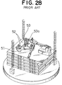
- FIG. 28 A typical example of such conventional sample stages is illustrated in Fig. 28.
- This sample stage has a plurality of piezoelectric plates 52 supported by three legs 51 and a sample carrier 53 mounted on one of the piezoelectric plates 52.
- the legs 51 are made to move like a looper by applying driving voltage to the piezoelectric plates 52, thereby getting a sample plane 53a to change direction.
- Fig. 29A illustrates another conventional sample stage.
- This sample stage is provided with a running arm 55 pivotally mounted to a movable rod 56 by a connecting pin 54, and a sample carrier 58 is formed at one end of the running arm 55.
- a stopper 57 is fixed to the sample stage.
- a sample plane 58a is changed by linearly moving the movable rod 56 upward together with the connecting pin 54 from the state shown in Fig. 29A and pivoting one end of the running arm 55, at which the sample carrier 58 is mounted, upward about the stopper 57 in contact with the other end of the running arm 55, as shown in Fig. 29B.
- the above-mentioned conventional sample stages have the following problems. Since the sample plane 53a is moved by extending and contracting the plural piezoelectric plates 52 by the voltage application in the sample stage shown in Fig. 28, it takes a long time to change the direction of the sample plane 53a over a wide range. Furthermore, the method of applying the drive voltage to the plural piezoelectric plates 52 is complicated, and the directional change is unstable since the coefficient of friction of the bottom surface of each arm 51 is liable to change.
- the present invention aims to solve these problems, and it is an object of the present invention to provide a sample stage of a scanning probe microscope capable of changing the direction of a sample plane stably over a wide range in a simple operation.
- a sample stage of a scanning probe microscope head of the present invention which is comprised of a flexible shaft consisting of an inner flexible tube and an outer flexible tube, fixtures for fixing both ends of the outer flexible tube, a displacement lead-in portion for displacing one end of the inner flexible tube relative to the outer flexible tube, a sample carrier portion for holding a sample and changing the direction of a plane of the sample by turning about a turn axis, and a displacement transmitting means connected to the other end of the inner flexible tube for transmitting the displacement led into the inner flexible tube by the displacement lead-in portion to the sample carrier portion in order to turn the sample carrier portion about the turn axis.
- Fig. 1 illustrates a sample stage of a scanning probe microscope head according to a first embodiment.
- a flexible shaft 200 consists of an inner flexible tube 210 and an outer flexible tube 220, and both ends of the outer flexible tube 220 are fixed by fixtures 310 and 320.
- a displacement lead-in portion 400 and a displacement lead-out portion 500 are respectively connected to one end and the other end of the inner flexible tube 210.
- a sample carrier portion 700 is connected to the displacement lead-out portion 500 through a coupling portion 600.
- the displacement lead-out portion 500 and the coupling portion 600 constitute a displacement transmitting means of the present invention.
- the flexible shaft 200 has a structure in which the inner flexible tube 210 is inserted in the outer flexible tube 220, and transmits the rotational or linear motion through the displacement of the inner flexible tube 210 relative to the outer flexible tube 220.
- a ultra-high vacuum bellows linear or rotary lead-in device 410 or 420 shown in Fig. 2 or 3 is used as the displacement lead-in portion 400.
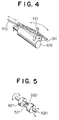
- a linear displacement lead-out device 510 and a linear coupling portion 610 shown in Fig. 4 can be used.
- the linear displacement lead-out device 510 has a catcher 511 having a square hole at an end thereof, and the linear coupling portion 610 has an engaging rod 611 to be fitted in the square hole of the catcher 511.
- the catcher 511 is inclined from the horizontal plane at an angle ⁇ almost equal to 45°, and the square hole thereof has such dimensions as to fit the engaging rod 611 therein even if the linear coupling portion 610 is turned at an angle of 90°.
- the catcher 511 and the engaging rod 611 are engaged with each other in correlation to the movement of the linear displacement lead-in portion 510, thereby converting the linear motion to the rotational motion.
- the mechanical engagement of the catcher 511 and the engaging rod 611 can be released by linearly moving the linear displacement lead-in portion 510 in the reverse direction and forming a void between the catcher 511 and the engaging rod 611.
- a rotary displacement lead-out device 520 and a rotary coupling portion 620 shown in Fig. 5 may be used.
- the rotary displacement lead-out device 520 is connected to the end of the inner flexible tube 210 and ends with two pins 521 embedded therein at the same distance from a center shaft of the inner flexible tube 210.
- the rotary coupling portion 620 is provided with a pull 621 to be inserted between the pins 521 at sufficient intervals.
- the rotation of the rotary displacement lead-in portion 520 is transmitted to the rotary coupling portion 600 through the pins 521 and the pull 621 as it is to turn the rotary coupling portion 600.
- the mechanical engagement of the pins 521 and the pull 621 can be released by turning the rotary displacement lead-out device 520 in the opposite direction and forming a void between the pins 521 and the pull 621.
- the fixture 310 fixes the end of the outer flexible tube 220 between a pair of fixing members 311 and 312, which have respective slots formed on opposed planes thereof, by screws 313, and the fixing members 311 and 312 are fixed to a fixing plane 314 by screws or the like.
- the linear lead-in device 410 and the end of the inner flexible tube 210 are connected through a connector 411 and screws 412.
- the fixture 320 on the side of the displacement lead-out portion 500 has the same structure as that of the fixture 310 shown in Fig. 6.
- Figs. 7A to 7D are respectively top, front, side and rear views of the sample carrier portion 700 using the linear displacement lead-out device 510 shown in Fig. 4.
- a turn base fitting 720 is screwed to a frame 710, and a turn base 740 having a turn shaft 730 jointly with the turn base fitting 720 as a bearing is mounted.
- a sample carrier 750 for holding a sample 900 is laid on the turn base 740, and the turn base fitting 720 is provided with a turn base stopper 760 for restricting the excessive movement of the turn base 740.
- turn shaft fixtures 731 and 732 are mounted on the turn shaft 730 to prevent the turn shaft 730 from separating from the turn base fitting 720 and the turn base 740.
- a turn engaging rod 733 as a part of the linear coupling portion 610 is screwed into the turn shaft fixture 731.
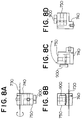
- Figs. 8A to 8C are respectively top, front and side views showing the relationship between the turn base 740 and the sample carrier 750.
- Fig. 8D is a side view showing a state in which the turn base 740 is turned at an angle of 90°.
- Fig. 9 is a perspective view explaining how to mount the sample carrier 750 to the turn base 740.
- a sample carrier insertion pin 741 having a neck slot 742 is screwed into the turn base 740 and a fitting hole 752 and a sample exchange female screw 753 are formed on the sample carrier 750.
- a U-shaped insertion pin presser spring 751 is inserted in a hole formed in the sample carrier 750 to be in contact with the inner surfaces of the fitting hole 752 and the sample exchange female screw 753.
- the insertion pin presser spring 751 is, as shown in Fig. 10, fitted in the neck slot 742 of the insertion pin 741, thereby connecting the turn base 740 and the sample carrier 750.
- the sample 900 is sandwiched between the sample carrier 750 and spring portions on both sides of a notch portion of a sample presser bar flat spring 901 fixed by bar flat spring screws 902, and pressed against the sample carrier 750 by elastic force of the spring portions.
- Fig. 12 illustrates a ultra-high vacuum scanning tunneling microscope head using the sample stage of the first embodiment.
- the linear lead-in portion 410 shown in Fig. 2 as the displacement lead-in portion 400 of the sample stage and the linear displacement lead-out device 510 and the linear coupling portion 610 shown in Fig. 4 as the displacement lead-out portion 500 and the coupling portion 600 are used.
- the operation of the first embodiment will be described with reference to Fig. 12.
- a sample stage flange 810 as a part of a vacuum vessel is provided with the linear lead-in device 410, a clamp linear lead-in device 820, a coarse drive rotary lead-in device 830, a coarse drive linear lead-in device 840 and a sight glass 850 on the air side, and a hanging bar 860 and an arm 870 on the vacuum side.
- the clamp linear lead-in device 820 has a clamp rod 821, whose leading end is conic, on the vacuum side thereof, and the hanging bar 860 has a clamp plate 861 with a conic projection at the end thereof and vibration-isolating hanging springs 862.
- a probe portion 880 constituted by the sample carrier portion 700, a probe 881, a scanning piezoelectric device 882 and a piezoelectric device attachment plate 883 is laid on a top plate 863 hung by the hanging springs 862.
- the flexible shaft 200, the fixtures 310 and 320, the linear displacement lead-out device 510 and a supporter 871 for holding the flexible shaft 200 to prevent the flexible shaft 200 from being twisted and bent by the own weight thereof are mounted to the arm 870.
- the linear lead-in device connector 411 is disposed between the linear lead-in device 410 and the fixture 310.
- the fitting and fixing position of the linear displacement lead-out device 510 and the linear coupling portion 610 is adjusted and set.
- the leading end of the clamp rod 821 is pressed against one side of the top plate 863 hung by the springs 862 by the clamp linear lead-in device 820, the sample carrier portion 700 and the probe portion 800 mounted on the top plate 863 are pushed together with the top plate 863.
- the direction of the turn base 740 is changed so that the sample 900 faces the probe 881.
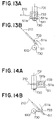
- the mount positions of the hanging springs 862, the clamp rod 821 and the clamp plate 861 and the mount angle of the turn shaft engaging rod 733 to the turn shaft fixture 731 are adjusted and set so that the turn engaging rod 733 is positioned as close as possible to and without contact with one inner end 511a of the square hole of the catcher 511 as shown in Figs. 13A and 13B in both the clamp and non-clamp states.
- the sample 900 is turned together with the turn base 740 to point upward as shown in Fig. 15.
- the sample 900 can be heated and cleaned.
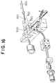
- the sample 900 can be exchanged with another by screwing a sample exchange male screw 921 formed at the leading end of a sample exchange rod 920 to the sample exchange female screw 753 of the sample carrier 750 and inserting and extracting the sample carrier 750 into and from the turn base 740 as shown in Fig. 16.
- the sample 900 is turned toward the probe 881 together with the turn base 740 as shown in Fig. 17. In this state, the scanning tunneling microscope can work.
- Both the outer flexible tube 220 and the inner flexible tube 210 constituting the flexible shaft 200 are shaped like a spring, and the material thereof is a C hard steel wire (JIS-G3521) which has large tensile strength and torsional stress and high abrasion resistance,or a stainless steel wire for a vacuum.
- the inner flexible tube 210 is 0.3mm in wire diameter, 1.0mm in outer spring diameter, 0mm in winding pitch and 20mm in bend radius
- the outer flexible tube 220 is 0.6mm in wire diameter, 2.5mm in outer spring diameter and 0.3mm in winding pitch.
- the bend radius of the flexible shaft 200 is 20mm.
- the outer flexible tube 220 is made of a coil of a flat steel wire so that the inner flexible tube 210 can smoothly slide inside the outer flexible tube 220.
- a perfluorinated grease, FOMBLIN whose vapor pressure is less than 10-9Pa may be interposed as a lubricant between the inner flexible tube 210 and the outer flexible tube 220.
- the fixing members 311 and 312 and the screws 313 constituting the fixtures 310 and 320, the linear lead-in portion connector 411 and the screws 412 are made of stainless steel (SUS-304 and JIS-G-4303, referred to as SUS hereinafter).
- the linear momentum of the linear lead-in device 410 used as the displacement lead-in portion 400 is 20mm and the rotation angle of the rotary lead-in device 420 is not limited.
- the linear lead-in device 410 and the rotary lead-in device 420 each have a drive shaft diameter of 6mm and a connecting flange diameter of ⁇ 34ICF, and either of these lead-in devices is attached to the sample stage flange 810 of ⁇ 203ICF shown in Fig. 12.
- the linear displacement lead-out device 510 or the rotary displacement lead-out device 520 as the displacement lead-out portion 500 and the linear coupling portion 610 or the rotary coupling portion 620 as the coupling portion 600 are made of SUS.
- the square hole of the catcher 511 used in the displacement lead-out device 510 shown in Fig. 12 is 5mm in width and 9mm in length, and the turn engaging rod 733, made of a steel wire (a piano wire of JIS-G3522, referred to as a piano wire) having a diameter of 1mm, is fitted therein.
- the turn engaging rod 733 is fixed in a hole formed on the side of the turn shaft fixture 731 in an interference fit.
- the frame 710 as a component of the sample carrier portion 700 is made of SUS, and has a width of 60mm, a height of 50mm and a depth of 8mm.
- a square slot having a width of 10+0.05mm, a height of 13mm and a depth of 8mm is formed in the center of the top of the frame 710 to insert and extract the sample carrier 750 therein and therefrom.
- a void is formed between the square slot of the frame 710 and the sample carrier 750 by making the width of the sample carrier 750 smaller than that of the square slot so that the turn can be kept even if thermal expansion is caused by the rise of temperature in degassing.
- the turn base fixture 720 made of SUS with outward dimensions of 205mm in width, 14mm in height and 6mm in depth is U-shaped with a square slot having a width of 10+0.05mm, a height of 8mm and a depth of 6mm, and is fixed to the frame 710 by screws.
- the turn shaft 730 made of a piano wire having a diameter of 1.5mm is inserted in holes respectively formed in the turn base fixture 720 and the turn base 740 made of SUS.
- the sample carrier 750 is made of SUS and shaped in a rectangular parallelepiped of 10-0.05mm in width, 10mm in height and 8mm in depth.
- the radius of curvature of the neck slot 742 of the sample carrier insertion pin 741 made of SUS, whose leading end is curved in a radius of curvature of 1.5mm, is 0.3mm and the U-shaped insertion pin presser spring 751 made of a piano wire having a diameter of 0.2mm is fitted in the neck slot 742.
- the sample presser bar flat spring 901 is made of a phosphor bronze plate (JIS-H3110) having a thickness of 0.2mm and fixed onto the sample carrier 750 by four screws (M1.2).
- the turn base stopper 760 and the turn shaft fixtures 731 and 732 are each made of SUS.
- the turn shaft fixtures 731 and 732 each have a diameter of 5.8mm, and the turn shaft 730 is fixed thereto by screws (M1.2).
- the total weight of a rotary body constituted by the sample carrier 750, the sampler presser bar flat spring 901, the turn base 740, the sample carrier insertion pin 741 and the insertion pin presser spring 751 is approximately 12g.
- the turn base 740 having an average surface roughness Ra (JIS-B0601) of less than 0.10a is laid on the plane of the square slot of the frame 710 having the same average surface roughness, thereby functioning as a STM.
- Figs. 18A to 18C are respectively top, front and side views showing a sample carrier portion in a sample stage according to a second embodiment of the present invention.
- a square slot in which the turn base 740 and the sample carrier 750 are housed is formed on the top of the frame 710, and a pair of slots 711a extending from the front side to the rear side of the frame 710 are formed on planes of the square slot.
- Ends of sample carrier presser bar flat springs 711 as sample carrier presser members in the present invention are respectively fixed in the slots 711a by screws.
- Figs. 19A to 19C illustrates a variation of the sample carrier portion according to the second embodiment.
- a pair of slots 712a extending downward from the top of the frame 710 are formed in the square slot of the frame 710, and ends of sample carrier presser bar flat springs 712 each made of plywood are respectively screwed in the slots 712a.
- metallic balls 713 are put between the other ends of the sample carrier presser bar flat springs 712 and both sides of the sample carrier 750. This serves to smoothly turn and insert the sample carrier 750 in the square slot of the frame 710, thereby achieving a reliable STM operation as described above.
- pits 714a are further formed to pierce the square slot and the slots 712a in the variation shown in Figs. 19A to 19C, and compression springs 714 are mounted in the pits 714a.
- the metallic balls 713 held by the sample carrier presser bar flat springs 712 are urged toward the sample carrier 750 by the compression springs 714. Therefore, the change of position of the turn shaft 730 in the axial direction is restricted and the rotary body including the sample carrier 750 can perform a reliable STM operation.
- magnets 715 are respectively fixed by an adhesive in the slots 711a formed in the square slot to extend from the front to the rear. Since the magnets 715 in the slots 711a attract both sides of the sample carrier 750, a reliable STM operation is achieved.
- the slots 711a and 712 are each 3.5mm in width and 3mm in depth, and the pits 714a are each 2.5mm in diameter and 8mm in depth.
- the sample carrier presser bar flat springs 711 are each made of a phosphor bronze plate (JIS-H3110) having a thickness of 0.1mm and a width of 3mm.
- Each of the sample carrier presser bar flat springs 712 is made of a two-ply plate of the same phosphor bronze as mentioned above, and has a hole of 1.8mm in diameter in a portion for holding the metallic ball 713.
- the metallic balls 713 each are made of a rigid ball (JIS-B1501) for a ball bearing having a diameter of 2mm.
- Each of the compression springs 714 is a coil spring of 0.2mm in wire diameter, 2.0mm in outer diameter, 16g/mm in spring constant and 12mm in free length.
- a rare earth magnet such as a neodymium (Nd-Fe-B) magnet or a samarium cobalt (Sm-Co) magnet, having a diameter of 2mm, a thickness of 3mm and a magnetic force of 2500 to 3200G, is used.
- a ball made of a precious stone, such as ruby, may be used instead of the metallic balls 713.
- the metallic balls 713 made of bearing rigid balls may be given the same effect as that of the magnets 715 in the variation shown in Figs. 21A to 21C by being magnetized.
- the frame 710 and the sample carrier 750 are made of highly permeable stainless steel (SUS430, JIS-G4303), or highly permeable Invar (Fe: 64%, Ni: 36%) or Super Invar (Fe: 63%, Ni: 32%, Co: 5%) having a small coefficient of thermal expansion, and a magnet circuit is closed when the sample carrier 750 is turned and inserted in the square slot of the frame 710.
- a curing agent consisting of thixotropic epoxy resin and aromatic amine or a vacuum leak inhibitor, Torr-Seal, having a low vapor pressure less than 10 ⁇ 7Pa is used.
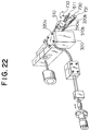
- Fig. 22 illustrates a sample stage according to a third embodiment of the present invention.
- numerals 320a, 320b, 510a and 510b respectively denote a fixture contact portion where the fixture 320 is in contact with the linear displacement lead-out device 510, a guide portion, a linear displacement lead-out contact portion where the linear displacement lead-out device 510 is in contact with the turn shaft fixture 731, and a guide contact portion.
- the fixture 731 and the linear displacement lead-out device 510 are so shaped that the catcher 511 is put in a horizontal position and the turn engaging rod 733 is escaped from the square hole of the catcher 511 when the inner flexible tube 210 of the flexible shaft 200 is pulled.
- the guide contact portion 510b of the linear displacement lead-out device 510 runs onto the guide portion 320b of the fixture 320, and the inner end 511a of the square hole of the catcher 511 is lifted up.
- the linear displacement lead-out device 510 is brought into planar contact with the fixture contact portion 320a, the catcher 511 is put in a horizontal position, and the turn engaging rod 733 is completely escaped from the square hole of the catcher 511.
- the turn engaging rod 733 is completely escaped from the square hole of the catcher 511, it is not in contact with the square hole of the catcher 511 even if vibration is applied to the whole STM in operation. Therefore, it is possible to continue a stable operation for a long time.
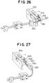
- Fig. 26 illustrates a sample stage according to a fourth embodiment of the present invention.
- the displacement led in the inner flexible shaft 210 of the flexible shaft 200 is transmitted to the sample carrier portion 700 through a gear transmission mechanism.
- a rack 512 is mounted in the linear displacement lead-out device 510, and a pinion 612 is mounted in the linear coupling portion 610.
- the rack 512 and the pinion 612 form what is called a rack and pinion structure.
- the advance and retreat of the linear displacement lead-out device 510 are converted into the rotation of the pinion 612 through the rack 512, thereby turning the sample 900 in the sample carrier portion 700.
- the rotation led out by the rotary displacement lead-out device 520 may be transmitted to the sample carrier portion 700 through a gear transmission mechanism.
- a main driving gear 522 formed in the rotary displacement lead-out device 520 and a driven gear 622 formed in the rotary coupling portion 620 form what is called a spur gear transmission structure.
- the rotation of the main driving gear 522 in the rotary displacement lead-out device 520 is transmitted to the driven gear 622 to turn the sample 900 in the sample carrier portion 700.
- the displacement led in the inner flexible tube 210 of the flexible shaft 200 is transmitted to the sample carrier portion 700 with reliability.
- the direction of the plane of the sample 900 is changed between the horizontal direction and the vertical direction in the above embodiments, it may be arbitrarily changed by changing the axial mount direction of the turn shaft 730 in the sample carrier portion 700.
- sample stage of the present invention is applied to a STM in the above embodiments
- present invention is not limited to the embodiments and may be applied as a sample stage of, for example, an atomic force microscope.
- Fixtures 310 and 320 fix both ends of an outer flexible tube 220 of a flexible shaft 200.
- a displacement lead-in portion 400 displaces one end of an inner flexible tube 210 of the flexible shaft 200 relative to the outer flexible tube 220, and a displacement lead-out portion 500 and a coupling portion 600 transmit the displacement led in the inner flexible tube 210 of the flexible shaft 200 to a sample carrier portion 700 to turn the sample carrier portion 700 about a turn axis, thereby getting a sample plane to change direction.
Landscapes
- Chemical & Material Sciences (AREA)
- Analytical Chemistry (AREA)
- Nuclear Medicine, Radiotherapy & Molecular Imaging (AREA)
- Health & Medical Sciences (AREA)
- General Health & Medical Sciences (AREA)
- General Physics & Mathematics (AREA)
- Physics & Mathematics (AREA)
- Radiology & Medical Imaging (AREA)
- Engineering & Computer Science (AREA)
- Nanotechnology (AREA)
- Crystallography & Structural Chemistry (AREA)
- Sampling And Sample Adjustment (AREA)
- Length Measuring Devices With Unspecified Measuring Means (AREA)
Abstract
There is disclosed a sample stage of a scanning probe microscope head capable of changing the direction of a sample plane stably over a wide range in a simple operation. Fixtures 310 and 320 fix both ends of an outer flexible tube 220 of a flexible shaft 200. A displacement lead-in portion 400 displaces one end of an inner flexible tube 210 of the flexible shaft 200 relative to the outer flexible tube 220, and a displacement lead-out portion 500 and a coupling portion 600 transmit the displacement led in the inner flexible tube 210 of the flexible shaft 200 to a sample carrier portion 700 to turn the sample carrier portion 700 about a turn axis, thereby getting a sample plane to change direction.
Description
- The present invention relates to a sample stage in the head of a scanning probe microscope, such as a scanning tunneling microscope (referred to as a STM hereinafter) or an atomic force microscope (referred to as an ATM hereinafter), and more particularly, to a sample stage capable of getting a sample plane to change direction by using a flexible shaft.
- STM head sample stages needed to coarsely focus on samples, heat sample planes and replace samples have been disclosed heretofore, for example, in the following literatures:
- 1. M. Ringger, B.W. Corb, H.R. Hidber, R. Schlogl, R. Weisendanger, A. Stemmer, L. Rosenthaler, A.J. Brunner, P.C. Oelhafen and H.J. Gruntherodt: IBM J. Res. Develop., Vol. 30, No. 5, pp. 500-508, 1986.
- 2. Th. Berghaus, H. Neddermeyer and St. Tosch: IBM J. Res. Develop., Vol. 30, No. 5, pp. 520-524, 1986.
- 3. S. Chiang, R.J. Wilson, Ch. Gerber and V.M. Hallmark: J. Vac. Sci. Technol. A, Vol. 6, No. 2, pp.386-389, 1988.
- 4. J.E. Demuth, R.J. Hamers, R.M. Tromp and M.E. Welland: J. Vac. Sci. Technol. A, Vol. 4, No. 3, pp.1320-1323, 1986.
- 5. M. Okano, K. Kajimura, S. Wakiyama, F. Sakai, W. Mizutani and M. Ono: J. Vac. Sci. Technol. A, Vol. 5, No. 6, pp. 1313-3320, 1987.
- 6. H. Bando, H. Tokumoto, A. Zettl and K. Kajimura: Ultramicroscopy, No. 42-44, pp. 1627-1631, 1992.
- A typical example of such conventional sample stages is illustrated in Fig. 28. This sample stage has a plurality of
piezoelectric plates 52 supported by threelegs 51 and asample carrier 53 mounted on one of thepiezoelectric plates 52. Thelegs 51 are made to move like a looper by applying driving voltage to thepiezoelectric plates 52, thereby getting asample plane 53a to change direction. Fig. 29A illustrates another conventional sample stage. This sample stage is provided with a runningarm 55 pivotally mounted to amovable rod 56 by a connectingpin 54, and asample carrier 58 is formed at one end of the runningarm 55. On the side of the other end of the runningarm 55, astopper 57 is fixed to the sample stage. In this sample stage, the direction of a sample plane 58a is changed by linearly moving themovable rod 56 upward together with the connectingpin 54 from the state shown in Fig. 29A and pivoting one end of the runningarm 55, at which thesample carrier 58 is mounted, upward about thestopper 57 in contact with the other end of the runningarm 55, as shown in Fig. 29B. - However, the above-mentioned conventional sample stages have the following problems. Since the
sample plane 53a is moved by extending and contracting the pluralpiezoelectric plates 52 by the voltage application in the sample stage shown in Fig. 28, it takes a long time to change the direction of thesample plane 53a over a wide range. Furthermore, the method of applying the drive voltage to the pluralpiezoelectric plates 52 is complicated, and the directional change is unstable since the coefficient of friction of the bottom surface of eacharm 51 is liable to change. - On the other hand, in the sample stage illustrated in Fig. 29, since the running
arm 55 is mounted pivotally in a vertical plane by the connectingpin 54, the direction of the sample plane 58a can be also changed only in a vertical plane. - The present invention aims to solve these problems, and it is an object of the present invention to provide a sample stage of a scanning probe microscope capable of changing the direction of a sample plane stably over a wide range in a simple operation.
- In order to achieve the above object, there is provided a sample stage of a scanning probe microscope head of the present invention which is comprised of a flexible shaft consisting of an inner flexible tube and an outer flexible tube, fixtures for fixing both ends of the outer flexible tube, a displacement lead-in portion for displacing one end of the inner flexible tube relative to the outer flexible tube, a sample carrier portion for holding a sample and changing the direction of a plane of the sample by turning about a turn axis, and a displacement transmitting means connected to the other end of the inner flexible tube for transmitting the displacement led into the inner flexible tube by the displacement lead-in portion to the sample carrier portion in order to turn the sample carrier portion about the turn axis.
-
- Fig. 1 is a perspective view of a sample stage of a scanning probe microscope head according to a first embodiment of the present invention;
- Fig. 2 is a perspective view of a linear lead-in device used as a displacement lead-in portion;
- Fig. 3 is a perspective view of a rotary lead-in device used as the displacement lead-in portion;
- Fig. 4 is a perspective view of a linear displacement lead-out portion;
- Fig. 5 is a perspective view of a rotary displacement lead-out portion;
- Fig. 6 is a perspective view of a fixture;
- Figs. 7A to 7D are respectively top, front, side and rear views of a sample carrier portion;
- Figs. 8A to 8C are respectively top, front and side views showing the relationship between a turn base and a sample carrier, and Fig. 8D is a side view showing a state in which the turn base is turned at an angle of 90°;
- Fig. 9 is a perspective view showing how to mount the sample carrier on the turn base;
- Fig. 10 is a partly enlarged view showing the sample carrier mounted on the turn base;
- Figs. 11A to 11C are respectively top, front and side views showing the relationship between the sample carrier and a sample;
- Fig. 12 is a perspective view of a ultra-high vacuum scanning tunneling microscope head using the sample stage in the first embodiment;
- Figs. 13A, 13B, 14A and 14B are views showing the relationship between a turn engaging rod and a catcher;
- Figs. 15 to 17 are views showing operations of the scanning tunneling microscope head shown in Fig. 12;
- Figs. 18A to 18C are respectively top, front and side views of a sample carrier portion according to a second embodiment of the present invention;
- Figs. 19A to 19C are respectively top, front and side views of a sample carrier portion according to a first variation of the second embodiment;
- Figs. 20A to 20C are respectively top, front and side views of a sample carrier portion according to a second variation of the second embodiment;
- Figs. 21A to 21C are respectively top, front and side views of a sample carrier portion according to a third variation of the second embodiment;
- Fig. 22 is a perspective view of a sample stage according to a third embodiment;
- Figs. 23A, 23B, 24A, 24B, 25A and 25B are views showing a displacement transmission means in the third embodiment;
- Fig. 26 is a perspective view of a sample stage according to a fourth embodiment;
- Fig. 27 is a perspective view of a sample stage according to a variation of the fourth embodiment;
- Fig. 28 is a perspective view of a conventional sample stage; and
- Fig. 29A is a side view of another conventional sample stage in operation of a STM and Fig. 29B is a side view showing a state in which the direction of a sample plane of the sample stage shown in Fig. 29A is changed.
- Embodiments of the present invention will now be described with reference to the drawings.
- Fig. 1 illustrates a sample stage of a scanning probe microscope head according to a first embodiment. Referring to Fig. 1, a
flexible shaft 200 consists of an innerflexible tube 210 and an outerflexible tube 220, and both ends of the outerflexible tube 220 are fixed byfixtures portion 400 and a displacement lead-outportion 500 are respectively connected to one end and the other end of the innerflexible tube 210. Asample carrier portion 700 is connected to the displacement lead-outportion 500 through acoupling portion 600. The displacement lead-outportion 500 and thecoupling portion 600 constitute a displacement transmitting means of the present invention. - The
flexible shaft 200 has a structure in which the innerflexible tube 210 is inserted in the outerflexible tube 220, and transmits the rotational or linear motion through the displacement of the innerflexible tube 210 relative to the outerflexible tube 220. A ultra-high vacuum bellows linear or rotary lead-indevice portion 400. - As the displacement lead-out
portion 500 and thecoupling portion 600, for example, a linear displacement lead-outdevice 510 and alinear coupling portion 610 shown in Fig. 4 can be used. The linear displacement lead-outdevice 510 has acatcher 511 having a square hole at an end thereof, and thelinear coupling portion 610 has an engagingrod 611 to be fitted in the square hole of thecatcher 511. Thecatcher 511 is inclined from the horizontal plane at an angle α almost equal to 45°, and the square hole thereof has such dimensions as to fit the engagingrod 611 therein even if thelinear coupling portion 610 is turned at an angle of 90°. Thecatcher 511 and the engagingrod 611 are engaged with each other in correlation to the movement of the linear displacement lead-inportion 510, thereby converting the linear motion to the rotational motion. The mechanical engagement of thecatcher 511 and the engagingrod 611 can be released by linearly moving the linear displacement lead-inportion 510 in the reverse direction and forming a void between thecatcher 511 and the engagingrod 611. - As the displacement lead-out
portion 500 and thecoupling portion 600, for example, a rotary displacement lead-outdevice 520 and arotary coupling portion 620 shown in Fig. 5 may be used. The rotary displacement lead-outdevice 520 is connected to the end of the innerflexible tube 210 and ends with twopins 521 embedded therein at the same distance from a center shaft of the innerflexible tube 210. Therotary coupling portion 620 is provided with apull 621 to be inserted between thepins 521 at sufficient intervals. The rotation of the rotary displacement lead-inportion 520 is transmitted to therotary coupling portion 600 through thepins 521 and thepull 621 as it is to turn therotary coupling portion 600. The mechanical engagement of thepins 521 and thepull 621 can be released by turning the rotary displacement lead-outdevice 520 in the opposite direction and forming a void between thepins 521 and thepull 621. - As shown in fig. 6, the
fixture 310 fixes the end of the outerflexible tube 220 between a pair of fixingmembers screws 313, and the fixingmembers plane 314 by screws or the like. The linear lead-indevice 410 and the end of the innerflexible tube 210 are connected through aconnector 411 and screws 412. Thefixture 320 on the side of the displacement lead-outportion 500 has the same structure as that of thefixture 310 shown in Fig. 6. - Figs. 7A to 7D are respectively top, front, side and rear views of the
sample carrier portion 700 using the linear displacement lead-outdevice 510 shown in Fig. 4. A turn base fitting 720 is screwed to aframe 710, and aturn base 740 having aturn shaft 730 jointly with the turn base fitting 720 as a bearing is mounted. Asample carrier 750 for holding asample 900 is laid on theturn base 740, and the turn base fitting 720 is provided with aturn base stopper 760 for restricting the excessive movement of theturn base 740. Furthermore, turnshaft fixtures turn shaft 730 to prevent theturn shaft 730 from separating from the turn base fitting 720 and theturn base 740. Aturn engaging rod 733 as a part of thelinear coupling portion 610 is screwed into theturn shaft fixture 731. - Figs. 8A to 8C are respectively top, front and side views showing the relationship between the
turn base 740 and thesample carrier 750. Fig. 8D is a side view showing a state in which theturn base 740 is turned at an angle of 90°. - Fig. 9 is a perspective view explaining how to mount the
sample carrier 750 to theturn base 740. A samplecarrier insertion pin 741 having aneck slot 742 is screwed into theturn base 740 and afitting hole 752 and a sample exchangefemale screw 753 are formed on thesample carrier 750. Furthermore, a U-shaped insertionpin presser spring 751 is inserted in a hole formed in thesample carrier 750 to be in contact with the inner surfaces of thefitting hole 752 and the sample exchangefemale screw 753. When thesample carrier 750 is moved toward theturn base 740 along an axis X-X, the insertionpin presser spring 751 is, as shown in Fig. 10, fitted in theneck slot 742 of theinsertion pin 741, thereby connecting theturn base 740 and thesample carrier 750. - As shown in Figs. 11A to 11C, the
sample 900 is sandwiched between thesample carrier 750 and spring portions on both sides of a notch portion of a sample presser barflat spring 901 fixed by bar flat spring screws 902, and pressed against thesample carrier 750 by elastic force of the spring portions. - Fig. 12 illustrates a ultra-high vacuum scanning tunneling microscope head using the sample stage of the first embodiment. In this head, the linear lead-in
portion 410 shown in Fig. 2 as the displacement lead-inportion 400 of the sample stage and the linear displacement lead-outdevice 510 and thelinear coupling portion 610 shown in Fig. 4 as the displacement lead-outportion 500 and thecoupling portion 600 are used. The operation of the first embodiment will be described with reference to Fig. 12. - A
sample stage flange 810 as a part of a vacuum vessel is provided with the linear lead-indevice 410, a clamp linear lead-indevice 820, a coarse drive rotary lead-indevice 830, a coarse drive linear lead-indevice 840 and asight glass 850 on the air side, and a hangingbar 860 and anarm 870 on the vacuum side. The clamp linear lead-indevice 820 has aclamp rod 821, whose leading end is conic, on the vacuum side thereof, and the hangingbar 860 has aclamp plate 861 with a conic projection at the end thereof and vibration-isolating hanging springs 862. Aprobe portion 880 constituted by thesample carrier portion 700, aprobe 881, ascanning piezoelectric device 882 and a piezoelectricdevice attachment plate 883 is laid on atop plate 863 hung by the hanging springs 862. Theflexible shaft 200, thefixtures device 510 and asupporter 871 for holding theflexible shaft 200 to prevent theflexible shaft 200 from being twisted and bent by the own weight thereof are mounted to thearm 870. The linear lead-indevice connector 411 is disposed between the linear lead-indevice 410 and thefixture 310. - First, the fitting and fixing position of the linear displacement lead-out
device 510 and thelinear coupling portion 610 is adjusted and set. When the leading end of theclamp rod 821 is pressed against one side of thetop plate 863 hung by thesprings 862 by the clamp linear lead-indevice 820, thesample carrier portion 700 and the probe portion 800 mounted on thetop plate 863 are pushed together with thetop plate 863. When one end of thetop plate 863 is brought into contact with the conic projection of theclamp plate 861, the motion of the clamp linear lead-indevice 820 is stopped, and thesample carrier portion 700 and the probe portion 800 are brought into a clamp state together with thetop plate 863 hung by the hanging springs 862, thereby stopping the swing of thetop plate 863 caused by the hanging springs 862. - By pulling the inner
flexible tube 210 by the linear lead-indevice 410 in such clamp state, as shown in Fig. 12, the direction of theturn base 740 is changed so that thesample 900 faces theprobe 881. The mount positions of the hanging springs 862, theclamp rod 821 and theclamp plate 861 and the mount angle of the turnshaft engaging rod 733 to theturn shaft fixture 731 are adjusted and set so that theturn engaging rod 733 is positioned as close as possible to and without contact with oneinner end 511a of the square hole of thecatcher 511 as shown in Figs. 13A and 13B in both the clamp and non-clamp states. - Subsequently, it is ascertained that, when the inner
flexible tube 210 is extended by moving the linear lead-indevice 410 in the opposite direction in the clamp state and theturn shaft fixture 731 is turned while making theturn engaging rod 733 in contact with the otherinner end 511b of the square hole of thecatcher 511 as shown in Figs. 14A and 14B, theturn base 740 is gradually turned together with theturn shaft fixture 731 by a couple resulting from the own weight thereof and finally stopped by theturn base stopper 760. Furthermore, it is ascertained that, when theturn shaft fixture 731 is reversely turned by pulling the innerflexible tube 210 again, theturn base 740 is reversely turned by the couple resulting from the own weight thereof as shown in Figs. 13A and 13B and finally stopped by the contact with theframe 710 and that theturn engaging rod 733 is positioned in the square hole without contact with thecatcher 511 in the non-clamp state. - After such adjustment and setting, when the inner
flexible tube 210 is advanced by the linear lead-indevice 410, thesample 900 is turned together with theturn base 740 to point upward as shown in Fig. 15. By radiating, for example, aninfrared ray 910 onto the plane of thesample 900 in this state, thesample 900 can be heated and cleaned. Furthermore, thesample 900 can be exchanged with another by screwing a sampleexchange male screw 921 formed at the leading end of asample exchange rod 920 to the sample exchangefemale screw 753 of thesample carrier 750 and inserting and extracting thesample carrier 750 into and from theturn base 740 as shown in Fig. 16. On the other hand, when the innerflexible tube 210 is retreated by the linear lead-indevice 410, thesample 900 is turned toward theprobe 881 together with theturn base 740 as shown in Fig. 17. In this state, the scanning tunneling microscope can work. - Materials and dimensions of the components of the sample stage in the first embodiment will be described in detail. Both the outer
flexible tube 220 and the innerflexible tube 210 constituting theflexible shaft 200 are shaped like a spring, and the material thereof is a C hard steel wire (JIS-G3521) which has large tensile strength and torsional stress and high abrasion resistance,or a stainless steel wire for a vacuum. The innerflexible tube 210 is 0.3mm in wire diameter, 1.0mm in outer spring diameter, 0mm in winding pitch and 20mm in bend radius, and the outerflexible tube 220 is 0.6mm in wire diameter, 2.5mm in outer spring diameter and 0.3mm in winding pitch. The bend radius of theflexible shaft 200 is 20mm. If the bend radius may be larger, the outerflexible tube 220 is made of a coil of a flat steel wire so that the innerflexible tube 210 can smoothly slide inside the outerflexible tube 220. In order to further the smooth slide, a perfluorinated grease, FOMBLIN, whose vapor pressure is less than 10-9Pa may be interposed as a lubricant between the innerflexible tube 210 and the outerflexible tube 220. - The fixing
members screws 313 constituting thefixtures portion connector 411 and thescrews 412 are made of stainless steel (SUS-304 and JIS-G-4303, referred to as SUS hereinafter). - The linear momentum of the linear lead-in
device 410 used as the displacement lead-inportion 400 is 20mm and the rotation angle of the rotary lead-indevice 420 is not limited. The linear lead-indevice 410 and the rotary lead-indevice 420 each have a drive shaft diameter of 6mm and a connecting flange diameter of ⌀ 34ICF, and either of these lead-in devices is attached to thesample stage flange 810 of ⌀ 203ICF shown in Fig. 12. - The linear displacement lead-out
device 510 or the rotary displacement lead-outdevice 520 as the displacement lead-outportion 500 and thelinear coupling portion 610 or therotary coupling portion 620 as thecoupling portion 600 are made of SUS. - The square hole of the
catcher 511 used in the displacement lead-outdevice 510 shown in Fig. 12 is 5mm in width and 9mm in length, and theturn engaging rod 733, made of a steel wire (a piano wire of JIS-G3522, referred to as a piano wire) having a diameter of 1mm, is fitted therein. Theturn engaging rod 733 is fixed in a hole formed on the side of theturn shaft fixture 731 in an interference fit. - The
frame 710 as a component of thesample carrier portion 700 is made of SUS, and has a width of 60mm, a height of 50mm and a depth of 8mm. A square slot having a width of 10+0.05mm, a height of 13mm and a depth of 8mm is formed in the center of the top of theframe 710 to insert and extract thesample carrier 750 therein and therefrom. A void is formed between the square slot of theframe 710 and thesample carrier 750 by making the width of thesample carrier 750 smaller than that of the square slot so that the turn can be kept even if thermal expansion is caused by the rise of temperature in degassing. - The
turn base fixture 720 made of SUS with outward dimensions of 205mm in width, 14mm in height and 6mm in depth is U-shaped with a square slot having a width of 10+0.05mm, a height of 8mm and a depth of 6mm, and is fixed to theframe 710 by screws. Theturn shaft 730 made of a piano wire having a diameter of 1.5mm is inserted in holes respectively formed in theturn base fixture 720 and theturn base 740 made of SUS. - The
sample carrier 750 is made of SUS and shaped in a rectangular parallelepiped of 10-0.05mm in width, 10mm in height and 8mm in depth. The radius of curvature of theneck slot 742 of the samplecarrier insertion pin 741 made of SUS, whose leading end is curved in a radius of curvature of 1.5mm, is 0.3mm and the U-shaped insertionpin presser spring 751 made of a piano wire having a diameter of 0.2mm is fitted in theneck slot 742. The sample presser barflat spring 901 is made of a phosphor bronze plate (JIS-H3110) having a thickness of 0.2mm and fixed onto thesample carrier 750 by four screws (M1.2). Theturn base stopper 760 and theturn shaft fixtures turn shaft fixtures turn shaft 730 is fixed thereto by screws (M1.2). - The total weight of a rotary body constituted by the
sample carrier 750, the sampler presser barflat spring 901, theturn base 740, the samplecarrier insertion pin 741 and the insertionpin presser spring 751 is approximately 12g. Theturn base 740 having an average surface roughness Ra (JIS-B0601) of less than 0.10a is laid on the plane of the square slot of theframe 710 having the same average surface roughness, thereby functioning as a STM. - Figs. 18A to 18C are respectively top, front and side views showing a sample carrier portion in a sample stage according to a second embodiment of the present invention. A square slot in which the
turn base 740 and thesample carrier 750 are housed is formed on the top of theframe 710, and a pair ofslots 711a extending from the front side to the rear side of theframe 710 are formed on planes of the square slot. Ends of sample carrier presser bar flat springs 711 as sample carrier presser members in the present invention are respectively fixed in theslots 711a by screws. - When the
sample carrier 750 is turned and inserted in the square slot of theframe 710, both sides thereof are pressed by the elastic forces of the sample carrier presser bar flat springs 711 mounted in theslots 711a. Therefore, the change of displacement of theturn shaft 730 in the axial direction is restricted, and a rotary body constituted by thesample carrier 750, the sample presser barflat spring 901, theturn base 740, the samplecarrier insertion pin 741 and the insertionpin presser spring 751 can perform a reliable STM operation. - Figs. 19A to 19C illustrates a variation of the sample carrier portion according to the second embodiment. In the variation shown in Figs. 19A to 19C, a pair of
slots 712a extending downward from the top of theframe 710 are formed in the square slot of theframe 710, and ends of sample carrier presser bar flat springs 712 each made of plywood are respectively screwed in theslots 712a. Furthermore,metallic balls 713 are put between the other ends of the sample carrier presser bar flat springs 712 and both sides of thesample carrier 750. This serves to smoothly turn and insert thesample carrier 750 in the square slot of theframe 710, thereby achieving a reliable STM operation as described above. - In another variation shown in Figs. 20A to 20C, pits 714a are further formed to pierce the square slot and the
slots 712a in the variation shown in Figs. 19A to 19C, and compression springs 714 are mounted in thepits 714a. Themetallic balls 713 held by the sample carrier presser bar flat springs 712 are urged toward thesample carrier 750 by the compression springs 714. Therefore, the change of position of theturn shaft 730 in the axial direction is restricted and the rotary body including thesample carrier 750 can perform a reliable STM operation. - In still another variation shown in Figs. 21a to 21C,
magnets 715 are respectively fixed by an adhesive in theslots 711a formed in the square slot to extend from the front to the rear. Since themagnets 715 in theslots 711a attract both sides of thesample carrier 750, a reliable STM operation is achieved. - Materials and dimensions of the components of the
sample carrier portion 700 in the second embodiment will now be described in detail. Theslots pits 714a are each 2.5mm in diameter and 8mm in depth. The sample carrier presser bar flat springs 711 are each made of a phosphor bronze plate (JIS-H3110) having a thickness of 0.1mm and a width of 3mm. Each of the sample carrier presser bar flat springs 712 is made of a two-ply plate of the same phosphor bronze as mentioned above, and has a hole of 1.8mm in diameter in a portion for holding themetallic ball 713. Themetallic balls 713 each are made of a rigid ball (JIS-B1501) for a ball bearing having a diameter of 2mm. Each of the compression springs 714 is a coil spring of 0.2mm in wire diameter, 2.0mm in outer diameter, 16g/mm in spring constant and 12mm in free length. As themagnets 715, a rare earth magnet, such as a neodymium (Nd-Fe-B) magnet or a samarium cobalt (Sm-Co) magnet, having a diameter of 2mm, a thickness of 3mm and a magnetic force of 2500 to 3200G, is used. - A ball made of a precious stone, such as ruby, may be used instead of the
metallic balls 713. Furthermore, themetallic balls 713 made of bearing rigid balls may be given the same effect as that of themagnets 715 in the variation shown in Figs. 21A to 21C by being magnetized. - If the
metallic balls 713 in the variation shown in Figs. 21A to 21C are magnetized, theframe 710 and thesample carrier 750 are made of highly permeable stainless steel (SUS430, JIS-G4303), or highly permeable Invar (Fe: 64%, Ni: 36%) or Super Invar (Fe: 63%, Ni: 32%, Co: 5%) having a small coefficient of thermal expansion, and a magnet circuit is closed when thesample carrier 750 is turned and inserted in the square slot of theframe 710. - As the adhesive for fixing the
magnets 715 in theslots 711a, for example, a curing agent consisting of thixotropic epoxy resin and aromatic amine or a vacuum leak inhibitor, Torr-Seal, having a low vapor pressure less than 10⁻⁷Pa is used. - Fig. 22 illustrates a sample stage according to a third embodiment of the present invention. Referring to Fig. 22,
numerals fixture 320 is in contact with the linear displacement lead-outdevice 510, a guide portion, a linear displacement lead-out contact portion where the linear displacement lead-outdevice 510 is in contact with theturn shaft fixture 731, and a guide contact portion. Thefixture 731 and the linear displacement lead-outdevice 510 are so shaped that thecatcher 511 is put in a horizontal position and theturn engaging rod 733 is escaped from the square hole of thecatcher 511 when the innerflexible tube 210 of theflexible shaft 200 is pulled. - The operation of the sample stage in the third embodiment will now be described. When the inner
flexible tube 210 is expanded, as shown in Figs. 23A and 23B, theturn shaft fixture 731 is turned while theturn engaging rod 733 is kept in contact with theinner end 511b of the square hole of thecatcher 511. To the contrary, when the innerflexible tube 210 is pulled, as shown in Figs. 24A and 24B, theturn shaft fixture 731 is reversely turned while theturn engaging rod 733 is kept in contact with the otherinner end 511a of the square hole of thecatcher 511. During the reverse turn, theguide contact portion 510b of the linear displacement lead-outdevice 510 runs onto theguide portion 320b of thefixture 320, and theinner end 511a of the square hole of thecatcher 511 is lifted up. When the innerflexible tube 210 is further pulled, as shown in Figs. 25A and 25B, the linear displacement lead-outdevice 510 is brought into planar contact with thefixture contact portion 320a, thecatcher 511 is put in a horizontal position, and theturn engaging rod 733 is completely escaped from the square hole of thecatcher 511. - According to the third embodiment, since the
turn engaging rod 733 is completely escaped from the square hole of thecatcher 511, it is not in contact with the square hole of thecatcher 511 even if vibration is applied to the whole STM in operation. Therefore, it is possible to continue a stable operation for a long time. - Fig. 26 illustrates a sample stage according to a fourth embodiment of the present invention. In the fourth embodiment, the displacement led in the inner
flexible shaft 210 of theflexible shaft 200 is transmitted to thesample carrier portion 700 through a gear transmission mechanism. Referring to Fig. 26, arack 512 is mounted in the linear displacement lead-outdevice 510, and apinion 612 is mounted in thelinear coupling portion 610. Therack 512 and thepinion 612 form what is called a rack and pinion structure. The advance and retreat of the linear displacement lead-outdevice 510 are converted into the rotation of thepinion 612 through therack 512, thereby turning thesample 900 in thesample carrier portion 700. - As shown in Fig. 27, the rotation led out by the rotary displacement lead-out
device 520 may be transmitted to thesample carrier portion 700 through a gear transmission mechanism. Referring to Fig. 27, amain driving gear 522 formed in the rotary displacement lead-outdevice 520 and a drivengear 622 formed in therotary coupling portion 620 form what is called a spur gear transmission structure. The rotation of themain driving gear 522 in the rotary displacement lead-outdevice 520 is transmitted to the drivengear 622 to turn thesample 900 in thesample carrier portion 700. - According to the fourth embodiment, since the power is transmitted by using the gears, the displacement led in the inner
flexible tube 210 of theflexible shaft 200 is transmitted to thesample carrier portion 700 with reliability. - Though the direction of the plane of the
sample 900 is changed between the horizontal direction and the vertical direction in the above embodiments, it may be arbitrarily changed by changing the axial mount direction of theturn shaft 730 in thesample carrier portion 700. - Furthermore, though the sample stage of the present invention is applied to a STM in the above embodiments, the present invention is not limited to the embodiments and may be applied as a sample stage of, for example, an atomic force microscope.
- There is disclosed a sample stage of a scanning probe microscope head capable of changing the direction of a sample plane stably over a wide range in a simple operation.
Fixtures flexible tube 220 of aflexible shaft 200. A displacement lead-inportion 400 displaces one end of an innerflexible tube 210 of theflexible shaft 200 relative to the outerflexible tube 220, and a displacement lead-outportion 500 and acoupling portion 600 transmit the displacement led in the innerflexible tube 210 of theflexible shaft 200 to asample carrier portion 700 to turn thesample carrier portion 700 about a turn axis, thereby getting a sample plane to change direction.
Claims (14)
- A sample stage of a scanning probe microscope head, comprising:
a flexible shaft consisting of an inner flexible tube and an outer flexible tube;
fixtures for fixing both ends of said outer flexible tube;
a displacement lead-in portion for displacing one end of said inner flexible tube relative to said outer flexible tube;
a sample carrier portion for holding a sample and changing the direction of a plane of said sample by turning about a turn axis; and
displacement transmitting means connected to the other end of said inner flexible tube for transmitting the displacement led into said inner flexible tube by said displacement lead-in portion to said sample carrier portion to turn said sample carrier portion about said turn axis. - A sample stage as claimed in claim 1 wherein said displacement lead-in portion is a linear lead-in device for linearly displacing said inner flexible tube relative to said outer flexible tube in the longitudinal direction thereof.
- A sample stage as claimed in claim 2 wherein said displacement transmitting means has an engaging rod connected to said turn axis of said sample carrier portion and a catcher connected to the other end of said inner flexible tube, said catcher is engaged with said engaging rod at one end of the linear displacement of said inner flexible tube led by said displacement lead-in portion, and said catcher is disengaged from said engaging rod at the other end thereof.
- A sample stage as claimed in claim 1 wherein said displacement lead-in portion is a rotary lead-in device for turning said inner flexible tube relative to said outer flexible tube about an axis thereof.
- A sample stage as claimed in claim 4 wherein said displacement transmitting means has a pull connected to said turn axis of said sample carrier portion and a pair of pins connected to the other end of said inner flexible tube and to be engaged with said pull.
- A sample stage as claimed in claim 1 wherein said sample carrier portion has a frame, a sample carrier turnably mounted to said frame to hold said sample, and a sample carrier presser member for restricting the direction change of said sample carrier in the direction of said turn axis.
- A sample stage as claimed in claim 6 wherein said frame has a square slot formed to house said sample carrier therein, slots are respectively formed on both side planes of said square slot, and said sample carrier presser member is mounted in each of said slots.
- A sample stage as claimed in claim 7 wherein said sample carrier presser member is a bar flat spring for pressing said sample carrier housed in said square slot.
- A sample stage as claimed in claim 7 wherein said sample carrier presser member includes a bar flat spring made of a plywood and a ball supported by said plywood of said bar flat spring in contact with said sample carrier housed in said square slot.
- A sample stage as claimed in claim 7 wherein said sample carrier presser member includes a ball in contact with said sample carrier housed in said square slot and a compression spring for urging said ball toward said sample carrier.
- A sample stage as claimed in claim 7 wherein said sample carrier presser member is a magnet.
- A sample stage as claimed in claim 1 wherein said displacement transmitting means includes a gear transmission mechanism for transmitting the displacement led in said inner flexible tube by said displacement lead-in portion to said sample carrier portion.
- A sample stage as claimed in claim 12 wherein said gear transmission mechanism is a rack and pinion structure.
- A sample stage as claimed in claim 12 wherein said gear transmission mechanism is a spur gear structure.
Applications Claiming Priority (2)
| Application Number | Priority Date | Filing Date | Title |
|---|---|---|---|
| JP267267/93 | 1993-10-26 | ||
| JP5267267A JPH07122218A (en) | 1993-10-26 | 1993-10-26 | Sample stand for scanning probe microscope head |
Publications (1)
| Publication Number | Publication Date |
|---|---|
| EP0653628A1 true EP0653628A1 (en) | 1995-05-17 |
Family
ID=17442471
Family Applications (1)
| Application Number | Title | Priority Date | Filing Date |
|---|---|---|---|
| EP94116075A Ceased EP0653628A1 (en) | 1993-10-26 | 1994-10-12 | Sample stage for scanning probe microscope head |
Country Status (3)
| Country | Link |
|---|---|
| US (1) | US5530253A (en) |
| EP (1) | EP0653628A1 (en) |
| JP (1) | JPH07122218A (en) |
Cited By (1)
| Publication number | Priority date | Publication date | Assignee | Title |
|---|---|---|---|---|
| EP1916511A1 (en) | 2006-10-23 | 2008-04-30 | Universiteit Twente | Scanning probe microscope |
Families Citing this family (4)
| Publication number | Priority date | Publication date | Assignee | Title |
|---|---|---|---|---|
| US6736361B2 (en) | 2001-09-04 | 2004-05-18 | Nline Corporation | Semiconductor wafer positioning system and method |
| US7759656B1 (en) * | 2006-03-01 | 2010-07-20 | South Bay Technology, Inc. | Dual air particle sample cassette and methods for using same |
| US8063383B2 (en) | 2008-11-04 | 2011-11-22 | Sergiy Pryadkin | Inertial positioner and an optical instrument for precise positioning |
| US12340971B2 (en) * | 2023-03-23 | 2025-06-24 | Gabriel Demeneghi | Microscope stage fixture for horizontal rotation |
Citations (4)
| Publication number | Priority date | Publication date | Assignee | Title |
|---|---|---|---|---|
| US3952203A (en) * | 1972-07-21 | 1976-04-20 | Max-Planck-Gesellschaft Zur Forderung Der Wissenschaften E.V. | Object adjustment device for a charged particle beam apparatus |
| US4587431A (en) * | 1983-04-22 | 1986-05-06 | Jeol Ltd. | Specimen manipulating mechanism for charged-particle beam instrument |
| US4908519A (en) * | 1988-10-11 | 1990-03-13 | The Board Of Thustees Of The Leland Stanford Jr. University | Loading mechanism and support structure having improved vibration damping useful in scanning tunneling microscopy |
| US5157256A (en) * | 1991-08-08 | 1992-10-20 | Burleigh Instruments Inc. | System for exchanging samples and electrode tip units in a surface probe microscope |
Family Cites Families (6)
| Publication number | Priority date | Publication date | Assignee | Title |
|---|---|---|---|---|
| GB1225856A (en) * | 1968-08-30 | 1971-03-24 | ||
| DE2825417C2 (en) * | 1978-06-09 | 1980-08-07 | Max-Planck-Gesellschaft Zur Foerderung Der Wissenschaften E.V., 3400 Goettingen | Method and object setting device for setting a specimen slide with respect to the device axis of a corpuscular beam device |
| FR2608837B1 (en) * | 1986-12-23 | 1994-06-10 | Univ Metz | APPARATUS FOR HANDLING TRANSLATION OF AN ELEMENT, SUCH AS A SHAFT |
| JP2572107B2 (en) * | 1988-04-04 | 1997-01-16 | 三菱電機株式会社 | Coarse movement mechanism of scanning tunneling microscope |
| US4947042A (en) * | 1988-12-13 | 1990-08-07 | Mitsubishi Denki Kabushiki Kaisha | Tunnel unit and scanning head for scanning tunneling microscope |
| US5303035A (en) * | 1992-05-04 | 1994-04-12 | New Focus, Inc. | Precision micropositioner |
-
1993
- 1993-10-26 JP JP5267267A patent/JPH07122218A/en active Pending
-
1994
- 1994-10-06 US US08/319,243 patent/US5530253A/en not_active Expired - Fee Related
- 1994-10-12 EP EP94116075A patent/EP0653628A1/en not_active Ceased
Patent Citations (4)
| Publication number | Priority date | Publication date | Assignee | Title |
|---|---|---|---|---|
| US3952203A (en) * | 1972-07-21 | 1976-04-20 | Max-Planck-Gesellschaft Zur Forderung Der Wissenschaften E.V. | Object adjustment device for a charged particle beam apparatus |
| US4587431A (en) * | 1983-04-22 | 1986-05-06 | Jeol Ltd. | Specimen manipulating mechanism for charged-particle beam instrument |
| US4908519A (en) * | 1988-10-11 | 1990-03-13 | The Board Of Thustees Of The Leland Stanford Jr. University | Loading mechanism and support structure having improved vibration damping useful in scanning tunneling microscopy |
| US5157256A (en) * | 1991-08-08 | 1992-10-20 | Burleigh Instruments Inc. | System for exchanging samples and electrode tip units in a surface probe microscope |
Non-Patent Citations (2)
| Title |
|---|
| J.E.DEMUTH ET AL: "A simplified scanning tunneling microscope for surface science studies", JOURNAL OF VACUUM SCIENCE AND TECHNOLOGY: PART A., vol. 4, no. 3, May 1986 (1986-05-01), NEW YORK US, pages 1320 - 1323, XP002144838, DOI: doi:10.1116/1.573601 * |
| S.CHIANG ET AL: "An ultrahigh vacuum scanning tunneling microscope with interchangeable samples and tips", JOURNAL OF VACUUM SCIENCE AND TECHNOLOGY: PART A., vol. 6, no. 2, March 1988 (1988-03-01), NEW YORK US, pages 386 - 389 * |
Cited By (3)
| Publication number | Priority date | Publication date | Assignee | Title |
|---|---|---|---|---|
| EP1916511A1 (en) | 2006-10-23 | 2008-04-30 | Universiteit Twente | Scanning probe microscope |
| WO2008049570A1 (en) * | 2006-10-23 | 2008-05-02 | Universiteit Twente | Scanning probe microscope |
| US8438661B2 (en) | 2006-10-23 | 2013-05-07 | Universiteit Twente | Scanning probe microscope |
Also Published As
| Publication number | Publication date |
|---|---|
| US5530253A (en) | 1996-06-25 |
| JPH07122218A (en) | 1995-05-12 |
Similar Documents
| Publication | Publication Date | Title |
|---|---|---|
| US8899649B2 (en) | Clamping device | |
| US20120032380A1 (en) | PCB holder | |
| CN210430267U (en) | A floating plug-in device | |
| TW201032023A (en) | Electronic device having a retreating apparatus for external device | |
| US5530253A (en) | Sample stage for scanning probe microscope head | |
| CN110113929B (en) | Quick release electronic information board holder | |
| US4837445A (en) | Coarse adjusting device of scanning tunneling microscope | |
| CN219070575U (en) | Puncture needle guide assembly and automatic puncture needle feeding device | |
| JP6346276B2 (en) | Fixing device and fixing method for assembling two vehicle parts facing each other | |
| CN112901434B (en) | Optical image stabilization motor and electronics | |
| US8453488B2 (en) | Apparatus for bending resilient tab | |
| CN116419525A (en) | Fixed structure and cabinet | |
| CN217363267U (en) | Microphone bracket | |
| CN110323966A (en) | A kind of displacement bimorph enlarger | |
| CN117008261A (en) | An optical fiber adsorption and fixation device | |
| EP0708442A2 (en) | Disk storage and retrieval | |
| US7243688B2 (en) | Device for reforming socket contacts | |
| CN218313270U (en) | Instrument needle lifter | |
| JPS6215507Y2 (en) | ||
| CN219263635U (en) | Support base and display device | |
| JPS59501103A (en) | Product capture device for robot type manipulator | |
| CN112894666A (en) | Clamp for Pin needle | |
| CN216747126U (en) | Pressure detection clamp for magnetic stripe hardness detection | |
| JP2005164368A (en) | Loading and unloading testing machine | |
| CN217029611U (en) | Elastic clamping rotating shaft |
Legal Events
| Date | Code | Title | Description |
|---|---|---|---|
| PUAI | Public reference made under article 153(3) epc to a published international application that has entered the european phase |
Free format text: ORIGINAL CODE: 0009012 |
|
| AK | Designated contracting states |
Kind code of ref document: A1 Designated state(s): DE FR GB |
|
| 17P | Request for examination filed |
Effective date: 19950519 |
|
| 17Q | First examination report despatched |
Effective date: 19980119 |
|
| GRAG | Despatch of communication of intention to grant |
Free format text: ORIGINAL CODE: EPIDOS AGRA |
|
| STAA | Information on the status of an ep patent application or granted ep patent |
Free format text: STATUS: THE APPLICATION HAS BEEN REFUSED |
|
| 18R | Application refused |
Effective date: 20000106 |