EP0653620A1 - Optical sensor - Google Patents
Optical sensor Download PDFInfo
- Publication number
- EP0653620A1 EP0653620A1 EP94116032A EP94116032A EP0653620A1 EP 0653620 A1 EP0653620 A1 EP 0653620A1 EP 94116032 A EP94116032 A EP 94116032A EP 94116032 A EP94116032 A EP 94116032A EP 0653620 A1 EP0653620 A1 EP 0653620A1
- Authority
- EP
- European Patent Office
- Prior art keywords
- optical sensor
- container
- radiation source
- detector
- lens
- Prior art date
- Legal status (The legal status is an assumption and is not a legal conclusion. Google has not performed a legal analysis and makes no representation as to the accuracy of the status listed.)
- Granted
Links
Images
Classifications
-
- G—PHYSICS
- G01—MEASURING; TESTING
- G01N—INVESTIGATING OR ANALYSING MATERIALS BY DETERMINING THEIR CHEMICAL OR PHYSICAL PROPERTIES
- G01N21/00—Investigating or analysing materials by the use of optical means, i.e. using sub-millimetre waves, infrared, visible or ultraviolet light
- G01N21/01—Arrangements or apparatus for facilitating the optical investigation
- G01N21/03—Cuvette constructions
- G01N21/0303—Optical path conditioning in cuvettes, e.g. windows; adapted optical elements or systems; path modifying or adjustment
-
- D—TEXTILES; PAPER
- D06—TREATMENT OF TEXTILES OR THE LIKE; LAUNDERING; FLEXIBLE MATERIALS NOT OTHERWISE PROVIDED FOR
- D06F—LAUNDERING, DRYING, IRONING, PRESSING OR FOLDING TEXTILE ARTICLES
- D06F34/00—Details of control systems for washing machines, washer-dryers or laundry dryers
- D06F34/14—Arrangements for detecting or measuring specific parameters
- D06F34/22—Condition of the washing liquid, e.g. turbidity
-
- G—PHYSICS
- G01—MEASURING; TESTING
- G01N—INVESTIGATING OR ANALYSING MATERIALS BY DETERMINING THEIR CHEMICAL OR PHYSICAL PROPERTIES
- G01N21/00—Investigating or analysing materials by the use of optical means, i.e. using sub-millimetre waves, infrared, visible or ultraviolet light
- G01N21/17—Systems in which incident light is modified in accordance with the properties of the material investigated
- G01N21/47—Scattering, i.e. diffuse reflection
- G01N21/49—Scattering, i.e. diffuse reflection within a body or fluid
- G01N21/53—Scattering, i.e. diffuse reflection within a body or fluid within a flowing fluid, e.g. smoke
- G01N21/534—Scattering, i.e. diffuse reflection within a body or fluid within a flowing fluid, e.g. smoke by measuring transmission alone, i.e. determining opacity
-
- G—PHYSICS
- G01—MEASURING; TESTING
- G01V—GEOPHYSICS; GRAVITATIONAL MEASUREMENTS; DETECTING MASSES OR OBJECTS; TAGS
- G01V8/00—Prospecting or detecting by optical means
- G01V8/10—Detecting, e.g. by using light barriers
- G01V8/12—Detecting, e.g. by using light barriers using one transmitter and one receiver
-
- D—TEXTILES; PAPER
- D06—TREATMENT OF TEXTILES OR THE LIKE; LAUNDERING; FLEXIBLE MATERIALS NOT OTHERWISE PROVIDED FOR
- D06F—LAUNDERING, DRYING, IRONING, PRESSING OR FOLDING TEXTILE ARTICLES
- D06F2103/00—Parameters monitored or detected for the control of domestic laundry washing machines, washer-dryers or laundry dryers
- D06F2103/20—Washing liquid condition, e.g. turbidity
-
- G—PHYSICS
- G01—MEASURING; TESTING
- G01N—INVESTIGATING OR ANALYSING MATERIALS BY DETERMINING THEIR CHEMICAL OR PHYSICAL PROPERTIES
- G01N21/00—Investigating or analysing materials by the use of optical means, i.e. using sub-millimetre waves, infrared, visible or ultraviolet light
- G01N21/01—Arrangements or apparatus for facilitating the optical investigation
- G01N21/03—Cuvette constructions
- G01N2021/0389—Windows
- G01N2021/0392—Nonplanar windows
Definitions
- the advantage that can be achieved with the invention is, in particular, that the turbidity sensor can also be used in a washing machine or dishwasher because of the possible air / water differentiation as dry protection.
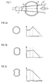
- the turbidity sensor shown schematically in FIG. 1 consists of an infrared radiation 4-emitting light-emitting diode 1, a phototransistor 2 and a measuring tube 3 arranged between these two components is connected to the laundry drum, it carries more or less cloudy washing water or water during the washing and rinsing processes or air if the water supply is interrupted.
- a phototransistor 2 In order to be able to clearly differentiate the two states “water / wash liquor in the measuring tube” and "air in the measuring tube” by measuring the intensity of the transmitted IR radiation 4 '.
- Is the measuring tube 3 on the side facing the light-emitting diode 1 and the phototransistor 2 each slightly curved inwards.
- the measuring tube 3 When filled with water, the measuring tube 3 then acts as a weak diverging lens, which widens the IR beam 4 emitted by the light-emitting diode 1 in the region of the phototransistor 2 (thick-line beam path in FIG. 1). By contrast, the measuring tube 3 filled with air has almost no lens effect. It allows the IR beam 4 to reach the phototransistor 2 without bending (see thin-dashed beam path in FIG. 1), which in this case measures a correspondingly higher IR intensity.
- FIG. 2 the corresponding intensity profiles on the phototransistor 2 are shown when using measuring tubes with a circular cross section (FIG. 2a) or with plane-parallel entry and exit windows (FIG. 2b). It can clearly be seen that only the measuring tube designed according to the invention allows a reliable differentiation of the air / water transition. The other two embodiments do not readily indicate whether the measuring tube contains air or water of a certain degree of turbidity.
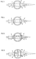
- the turbidity sensors shown in FIGS. 3 and 4 have measuring tubes 5 and 7, respectively, which are designed in the area of the incoming and outgoing IR rays 4, 4 'as plano-convex lenses 6, 6' or biconvex lenses 8, 8 '.
- These lens elements act as condensers that focus the divergent IR radiation 4 emitted by the light-emitting diode 1 onto the phototransistor 2 and increase the intensity there overall.
- the focusing effect of these optics is greatest in the case of air-filled measuring tubes 5, 7. It decreases significantly when the measuring tubes 5, 7 gradually fill with water or wash water.
- the turbidity sensor shown in FIG. 5 also has a measuring tube 9, the wall of which in the area of the entering and exiting IR rays 4, 4 'each has a cross section 10, 10' corresponding to a plano-convex lens.
- the converging lenses 11 and 12 arranged in front of and behind the measuring tube 9 are intended to improve the focusing effect of the measuring tube optics. With regard to their optical properties the sensors according to FIGS. 4 and 5 are to be regarded as equivalent.
- the property 6 shows a turbidity sensor in which a plane or biconvex lens is arranged in the interior of a measuring tube 16 having plane-parallel entry and exit windows 14/15.
- the air-filled system has a stronger focus on the IR radiation 4, so that one again observes an intensity curve on the phototransistor 2 corresponding to FIG. 2c.
Abstract
Description
In modernen Waschmaschinen werden die Wasch- und Spülvorgänge mit Hilfe einer elektronischen Steuereinheit überwacht und hinsichtlich des Energie- und Wasserverbrauchs optimiert. Als Meßwertgeber für die beispielsweise aus den GB-A-2 068 419, US-A-4,222,250 und EP-A-393 311 bekannten Steuereinheiten dienen sogenannte Trübungssensoren, deren Ausgangssignal ein Maß für die in der Waschlauge suspendierte Zeolithmenge (Wasserenthärter des Waschmittels) bzw. ein Maß für die Menge der durch die Tenside des Waschmittels hervorgerufenen Luftbläschen darstellt. Trübungssensoren bestehen üblicherweise aus einer Infrarotstrahlung emittierenden Leuchtdiode, einem Fototransistor und einem die beiden Komponenten aufnehmenden Gehäuse, das am Boden der Waschtrommel oder in einem Laugenabflußrohr angeordnet ist.In modern washing machines, the washing and rinsing processes are monitored using an electronic control unit and optimized with regard to energy and water consumption. So-called turbidity sensors serve as measuring sensors for the control units known from GB-A-2 068 419, US-A-4,222,250 and EP-A-393 311, for example represents a measure of the amount of air bubbles caused by the surfactants of the detergent. Turbidity sensors usually consist of an infrared radiation-emitting light-emitting diode, a phototransistor and a housing which accommodates the two components and which is arranged on the bottom of the washing drum or in an alkali drain pipe.
Gegenstand der Erfindung ist ein optischer Sensor, mit dem sich eindeutig feststellen läßt, ob ein Behältnis ein gasförmiges oder ein flüssiges Medium enthält. Der optische Sensor soll insbesondere auch den Trübungsgrad des flüssigen Mediums erfassen können. Diese Aufgabe wird erfindungsgemäß durch einen optischen Sensor gelöst, der die Merkmale der Patentansprüche 1, 5 oder 8 aufweist.The invention relates to an optical sensor with which it can be clearly determined whether a container contains a gaseous or a liquid medium. In particular, the optical sensor should also be able to detect the degree of turbidity of the liquid medium. This object is achieved according to the invention by an optical sensor which has the features of
Der mit der Erfindung erzielbare Vorteil besteht insbesondere darin, daß man den Trübungssensor aufgrund der möglichen Luft/Wasserunterscheidung auch als Trockengehschutz in einer Wasch- oder Spülmaschine einsetzen kann.The advantage that can be achieved with the invention is, in particular, that the turbidity sensor can also be used in a washing machine or dishwasher because of the possible air / water differentiation as dry protection.
Die abhängigen Ansprüche betreffen vorteilhafte Weiterbildungen und Ausgestaltungen der im folgenden anhand der Zeichnungen erläuterten Erfindung. Hierbei zeigt:
- Fig. 1 und 3 bis 6
- Ausführungsbeispiele erfindungsgemäßer Trübungssensoren
- Fig. 2
- die am Fototransistor des Trübungssensors gemessene IR-Intensität bei Verwendung verschiedener Meßrohre.
- 1 and 3 to 6
- Embodiments of turbidity sensors according to the invention
- Fig. 2
- the IR intensity measured at the phototransistor of the turbidity sensor when using different measuring tubes.
Der in Fig. 1 schematisch dargestellte Trübungssensor besteht aus einer Infrarotstrahlung 4 emittierenden Leuchtdiode 1, einem Fototransistor 2 und einem zwischen diesen beiden Komponenten angeordneten Meßrohr 3. Da das aus einem transparenten und chemikalienbeständigen Kunststoff (z. B. Polypropylen) oder Glas gefertigte Meßrohr 3 mit der Wäschetrommel in Verbindung steht, führt es während der Wasch- und Spülvorgange mehr oder weniger trübe Waschlauge bzw. Wasser oder bei unterbrochener Wasserzufuhr Luft. Um die beiden Zustände "Wasser/Waschlauge im Meßrohr" und "Luft im Meßrohr" durch Messung der Intensität der transmittierten IR-Strahlung 4' eindeutig voneinander unterscheiden zu können. Ist das Meßrohr 3 auf der der Leuchtdiode 1 und dem Fototransistor 2 zugewandten Seite jeweils leicht kugelförmig nach innen gewölbt. Wassergefüllt wirkt das Meßrohr 3 dann als schwache Zerstreuungslinse, die das von der Leuchtdiode 1 emittierte IR-Strahlenbündel 4 im Bereich des Fototransistors 2 aufweitet (dick gestrichelter Strahlengang in Fig. 1). Nahezu keine Linsenwirkung entfaltet hingegen das mit Luft gefüllte Meßrohr 3. Es läßt das IR-Strahlenbündel 4 ungebeugt zum Fototransistor 2 gelangen (s. dünngestrichelter Strahlengang in Fig. 1), der in diesem Fall eine entsprechend höhere IR-Intensität mißt.The turbidity sensor shown schematically in FIG. 1 consists of an infrared radiation 4-emitting light-emitting diode 1, a
Qualitativ ergibt sich damit der in Fig. 2c dargestellte Intensitätsverlauf am Fototransistor 2. Die maximale Intensität liefert das luftgefüllte Meßrohr 3 (keine Linsenwirkung). Mit dem Ansteigen des Wasserspiegels im Meßrohr 3 kommt die zerstreuende Wirkung des Systems immer stärker zum Tragen und die Intensität am Fototransistor 2 nimmt solange ab, bis das Meßrohr 3 vollständig mit Wasser gefüllt ist (Übergangsbereich). Die Zugabe von Waschmittel hat eine Trübung des Wassers zur Folge, wodurch sich dessen Absorptionsvermögen erhöht und weniger IR-Strahlung zum Fototransistor 2 gelangt.In terms of quality, this results in the intensity curve shown in FIG. 2c on the
Im oberen Teil der Fig. 2 sind die entsprechenden Intensitätsverläufe am Fototransistor 2 bei Verwendung von Meßrohren mit kreisförmigem Querschnitt (Fig. 2a) bzw. mit planparallelen Ein- und Austrittsfenstern (Fig. 2b) dargestellt. Man erkennt deutlich, daß nur das erfindungsgemäß ausgebildete Meßrohr eine sichere Unterscheidung des Übergangs Luft/Wasser erlaubt. Die beiden anderen Ausführungsformen lassen nicht ohne weiteres erkennen, ob das Meßrohr Luft oder Wasser eines bestimmten Trübungsgrades enthält.In the upper part of FIG. 2, the corresponding intensity profiles on the
Die in den Fig. 3 und 4 dargestellen Trübungssensoren besitzen Meßrohre 5 bzw. 7, die im Bereich des ein- und austretenden IR-Strahlenbündels 4, 4' jeweils als Plankonvexlinse 6, 6' bzw. Bikonvexlinse 8, 8' ausgebildet sind. Diese Linsenelemente wirken als Kondensoren, die die von der Leuchtdiode 1 emittierte divergente IR-Strahlung 4 auf den Fototransistor 2 fokussieren und die Intensität dort insgesamt erhöhen. Die fokussierende Wirkung dieser Optiken ist im Falle luftgefüllter Meßrohre 5, 7 am größten. Sie nimmt deutlich ab, wenn sich die Meßrohre 5, 7 allmählich mit Wasser oder Waschlauge füllen. Am Fototransistor 2 kann man also wieder einen der Fig. 2c entsprechenden Intensitätsverlauf beobachten. Aufgrund des Kondensoreffekts mißt der Fototransistor 2 allerdings jeweils eine deutlich höhere Intensität.The turbidity sensors shown in FIGS. 3 and 4 have
Der in Fig. 5 dargestellte Trübungssensor besitzt ebenfalls ein Meßrohr 9, dessen Wandung im Bereich des ein- und austretenden IR-Strahlenbündels 4, 4' jeweils einen einer Plankonvexlinse entsprechenden Querschnitt 10, 10' aufweist. Die im Strahlengang vor und hinter dem Meßrohr 9 angeordneten Sammellinsen 11 und 12 sollen die fokussierende Wirkung der Meßrohroptik verbessern. Hinsichtlich ihrer optischen Eigenschaften sind die Sensoren gemäß den Fig. 4 und 5 als äquivalent anzusehen.The turbidity sensor shown in FIG. 5 also has a measuring tube 9, the wall of which in the area of the entering and exiting
Die Eig. 6 zeigt einen Trübungssensor, bei dem eine Plan- oder Bikonvexlinse im Innern eines planparallele Ein- und Austrittsfenster 14/15 aufweisenden Meßrohrs 16 angeordnet ist. Auch hier wirkt das luftgefüllte System stärker fokussierend auf die IR-Strahlung 4, so daß man wieder einen der Fig. 2c entsprechenden Intensitätsverlauf am Phototransistor 2 beobachtet.The
Die Erfindung ist selbstverständlich nicht auf die beschriebenen Ausführungsbeispiele beschränkt. So ist es ohne weiteres möglich
- die Leuchtdiode durch eine andere Strahlungsquelle, insbesondere durch ein sichtbares Licht emittierendes Element zu ersetzen,
- anstelle des Fototransistors ein Fotoelement, eine Fotodiode oder einen Fotowiderstand zu verwenden,
- die Strahlungsquelle und den Strahlungsdetektor in den Schenkeln eines u-förmigen Halterungsteils anzuordnen und das Meßrohr zwischen den Schenkeln zu befestigen,
- weitere zerstreuende oder fokussierende Linsenelemente im Strahlengang zwischen der Strahlungsquelle und dem Meßrohr bzw. zwischen dem Meßrohr und dem Strahlungsdetektor anzuordnen,
- nur jeweils den der Strahlungsquelle oder den dem Strahlungsdetektor zu- oder abgewandten Bereich des Meßrohrs als Linsenelement auszubilden,
- einen Teil der Meßrohrwandung zu entfernen und eine vorgefertigte und ggf. aus einem anderen Material bestehende Linse mit den gewünschten Eigenschaften in diesem Fenster anzuordnen und
- das transmittierte Strahlenbündel mit Hilfe eines Spiegels in Richtung des Strahlungsdetektors umzulenken.
- to replace the light-emitting diode by another radiation source, in particular by a visible light-emitting element,
- to use a photo element, a photo diode or a photo resistor instead of the photo transistor
- to arrange the radiation source and the radiation detector in the legs of a U-shaped holding part and to fix the measuring tube between the legs,
- to arrange further diverging or focusing lens elements in the beam path between the radiation source and the measuring tube or between the measuring tube and the radiation detector,
- to form only the area of the measuring tube facing or facing away from the radiation source or the radiation detector as a lens element,
- to remove part of the measuring tube wall and to arrange a prefabricated lens, possibly made of another material, with the desired properties in this window and
- deflect the transmitted beam with the aid of a mirror in the direction of the radiation detector.
Die beschriebenen optischen Systeme lassen sich nicht nur in Waschmaschinen oder Spülmaschinen sondern auch in Systemen zur Überwachung der Wassertrübung und in medizinischen Geräten, beispielsweise zur Urin- oder Blutplasmaüberwachung einsetzen.The optical systems described can be used not only in washing machines or dishwashers, but also in systems for monitoring water turbidity and in medical devices, for example for monitoring urine or blood plasma.
Claims (13)
gekennzeichnet durch
die folgenden Merkmale:
marked by
the following characteristics:
dadurch gekennzeichnet,
daß die Wandung im ersten und/oder zweiten Bereich die Form einer sich ins Innere des Behältnisses (3) wölbenden Kugelfläche aufweist.Optical sensor according to claim 1,
characterized,
that the wall in the first and / or second area has the shape of a spherical surface that curves into the interior of the container (3).
dadurch gekennzeichnet,
daß der Wandungsquerschnitt im ersten und/oder zweiten Bereich die Form einer Plankonvexlinse (6, 6') aufweist, wobei die konvexe Fläche sich ins Innere des Behältnisses (5) erstreckt.Optical sensor according to claim 1,
characterized,
that the wall cross-section in the first and / or second region has the shape of a plano-convex lens (6, 6 '), the convex surface extending into the interior of the container (5).
dadurch gekennzeichnet,
daß der Wandungsquerschnitt im ersten und/oder zweiten Bereich die Form einer Bikonvexlinse (8, 8') aufweist.Optical sensor according to claim 1,
characterized,
that the wall cross-section has the shape of a biconvex lens (8, 8 ') in the first and / or second region.
gekennzeichnet durch
die folgenden Merkmale:
marked by
the following characteristics:
dadurch gekennzeichnet,
daß die Linse eine Plankonvexlinse oder eine Bikonvexlinse ist.Optical sensor according to claim 5,
characterized,
that the lens is a plano-convex lens or a biconvex lens.
dadurch gekennzeichnet,
daß eine erste Sammellinse (11) im Strahlengang zwischen der Strahlungsquelle (1) und dem Behaltnis (9) und/oder eine zweite Sammellinse (12) im Strahlengang zwischen dem Behältnis (9) und dem Detektor (2) angeordnet ist.Optical sensor according to one of claims 1 to 5,
characterized,
that a first collecting lens (11) in the beam path between the radiation source (1) and the container (9) and / or a second collecting lens (12) in the beam path between the container (9) and the detector (2) is arranged.
gekennzeichnet durch
die folgenden Merkmale:
marked by
the following characteristics:
dadurch gekennzeichnet,
daß das Behältnis (3) die Form eines Rohres aufweist und aus Glas oder einem transparenten Kunststoff besteht.Optical sensor according to one of claims 1 to 8,
characterized,
that the container (3) has the shape of a tube and consists of glass or a transparent plastic.
gekennzeichnet durch
eine Leuchtdiode oder Glühbirnchen als Strahlungsquelle (1).Optical sensor according to one of claims 1 to 9,
marked by
a light emitting diode or light bulb as a radiation source (1).
gekennzeichnet durch
eine Fotodiode, einen Fototransistor oder einen Fotowiderstand als Detektor (2).Optical sensor according to one of claims 1 to 10,
marked by
a photo diode, a photo transistor or a photo resistor as a detector (2).
Applications Claiming Priority (2)
| Application Number | Priority Date | Filing Date | Title |
|---|---|---|---|
| DE4336520 | 1993-10-26 | ||
| DE4336520A DE4336520C2 (en) | 1993-10-26 | 1993-10-26 | Optical sensor and its use |
Publications (2)
| Publication Number | Publication Date |
|---|---|
| EP0653620A1 true EP0653620A1 (en) | 1995-05-17 |
| EP0653620B1 EP0653620B1 (en) | 2001-09-12 |
Family
ID=6501060
Family Applications (1)
| Application Number | Title | Priority Date | Filing Date |
|---|---|---|---|
| EP94116032A Expired - Lifetime EP0653620B1 (en) | 1993-10-26 | 1994-10-11 | Optical sensor |
Country Status (4)
| Country | Link |
|---|---|
| EP (1) | EP0653620B1 (en) |
| JP (1) | JPH07190929A (en) |
| DE (1) | DE4336520C2 (en) |
| ES (1) | ES2164077T3 (en) |
Cited By (9)
| Publication number | Priority date | Publication date | Assignee | Title |
|---|---|---|---|---|
| EP0972486A1 (en) * | 1998-07-15 | 2000-01-19 | Whirlpool Corporation | Optical sensor |
| EP0992621A2 (en) * | 1998-10-07 | 2000-04-12 | BSH Bosch und Siemens Hausgeräte GmbH | Method for controlling a liquid carrying domestic apparatus and a domestic apparatus controlled according the method |
| EP1116471A2 (en) * | 1999-12-21 | 2001-07-18 | BSH Bosch und Siemens Hausgeräte GmbH | Method and device for determining the amount of dirt on tableware |
| EP1390715A2 (en) * | 2001-05-23 | 2004-02-25 | Hach Company | Optical turbidimeter with a lens tube |
| WO2006010746A1 (en) * | 2004-07-23 | 2006-02-02 | BSH Bosch und Siemens Hausgeräte GmbH | Method for supplying clear rinsing agents in a program-controlled dishwasher |
| US7690061B2 (en) | 2005-12-22 | 2010-04-06 | General Electric Company | Method and apparatus for controlling a laundering process |
| CN103270405A (en) * | 2010-12-15 | 2013-08-28 | W·福格尔 | Device for photometrically or spectrometrically examining a liquid sample |
| CN103645119A (en) * | 2013-12-17 | 2014-03-19 | 哈尔滨工程大学 | Point light source-based measuring device for measuring liquid density of matrix CCD (Charged Coupled Device) |
| WO2016203259A3 (en) * | 2015-06-19 | 2017-03-09 | Aqua21 Limited | An apparatus and a method for detecting the concentration of a substance in a fluid |
Families Citing this family (10)
| Publication number | Priority date | Publication date | Assignee | Title |
|---|---|---|---|---|
| US5672887A (en) * | 1995-11-29 | 1997-09-30 | Shaw; Benjamin G. | Optical detector for air in fluid line the same |
| DE19846248A1 (en) * | 1998-10-07 | 2000-04-13 | Bsh Bosch Siemens Hausgeraete | Process for monitoring and controlling the washing process in a laundry treatment machine and laundry treatment machine working according to this process |
| DE10209255B4 (en) * | 2002-02-27 | 2004-03-25 | SONOTEC Dr. zur Horst-Meyer & Münch oHG | ultrasonic device |
| DE10305093A1 (en) * | 2003-02-07 | 2004-08-19 | BSH Bosch und Siemens Hausgeräte GmbH | Method and device for determining and monitoring contamination states of different liquids |
| DE102006052887B4 (en) * | 2006-11-09 | 2013-11-14 | BSH Bosch und Siemens Hausgeräte GmbH | turbidity sensor |
| JP4909391B2 (en) * | 2009-08-25 | 2012-04-04 | パナソニック株式会社 | Washing machine |
| US8696827B2 (en) | 2010-12-01 | 2014-04-15 | Whirlpool Corporation | Dishwasher with imaging device for measuring load characteristics and a method for controlling same |
| DE102014115516A1 (en) * | 2014-10-24 | 2016-04-28 | Endress + Hauser Conducta Gesellschaft für Mess- und Regeltechnik mbH + Co. KG | Device for determining a measured value of a measured variable of the process automation technology in a liquid or gaseous medium, and its use and method of production |
| EP4345443A2 (en) * | 2017-10-04 | 2024-04-03 | Eli Lilly and Company | Tubing having visual markers for visualization of media therein |
| CN109406406A (en) * | 2018-10-21 | 2019-03-01 | 苏州高新区建金建智能科技有限公司 | A kind of device using optical-fiber laser monitoring trade effluent turbidity |
Citations (4)
| Publication number | Priority date | Publication date | Assignee | Title |
|---|---|---|---|---|
| EP0186712A1 (en) * | 1984-11-22 | 1986-07-09 | Personal Diagnostics, Inc. | Combined cuvette with integral optical elements and electrical circuit with photoemissive and photosensitive elements in intimate optical contact with said optical elements |
| DE3835347A1 (en) * | 1988-10-17 | 1990-04-19 | Eichler Hans Joachim Prof Dr | Liquid crystal cell with focusing windows |
| EP0393311A1 (en) * | 1989-01-27 | 1990-10-24 | Matsushita Electric Industrial Co., Ltd. | Washing machine with means for measuring the condition of the washing water |
| EP0404258A2 (en) * | 1989-06-20 | 1990-12-27 | Claudio Bonini | Test-tube with lenticular outside surface particularly for automatized clinical analysis |
Family Cites Families (9)
| Publication number | Priority date | Publication date | Assignee | Title |
|---|---|---|---|---|
| US3523738A (en) * | 1968-04-23 | 1970-08-11 | Bausch & Lomb | Lens system for the sample compartment of spectrophotometers,colorimeters and the like |
| JPS5143176B2 (en) * | 1972-01-14 | 1976-11-19 | ||
| GB2068419B (en) * | 1980-02-01 | 1983-10-19 | Tokyo Shibaura Electric Co | Washing machine |
| DE3246592C1 (en) * | 1982-12-16 | 1983-10-27 | Eppendorf Gerätebau Netheler + Hinz GmbH, 2000 Hamburg | Envelope for mixing and for optical examinations |
| US4619530A (en) * | 1983-07-08 | 1986-10-28 | Personal Diagnostics, Inc. | Combined cuvette with integral optical elements and electrical circuit with photoemissive and photosensitive elements in intimate optical contact with said optical elements |
| JPH03131298A (en) * | 1989-01-27 | 1991-06-04 | Matsushita Electric Ind Co Ltd | Washing machine |
| US5068798A (en) * | 1989-03-03 | 1991-11-26 | Precision Systems, Inc. | Process environment monitoring system |
| DE4139899A1 (en) * | 1991-12-04 | 1993-06-09 | Hoffmann, Alfred, Dr., 9200 Freiberg, De | Measuring turbidity and mass flow of suspended particles in liquids simultaneously - regulating diode emission power, averaging turbidity over repeated cycles and measuring transition time of flow rate |
| JPH05240774A (en) * | 1992-03-02 | 1993-09-17 | Hitachi Ltd | Optical cell and optical detecting device and sample separating/detecting device using them |
-
1993
- 1993-10-26 DE DE4336520A patent/DE4336520C2/en not_active Expired - Fee Related
-
1994
- 1994-10-11 ES ES94116032T patent/ES2164077T3/en not_active Expired - Lifetime
- 1994-10-11 EP EP94116032A patent/EP0653620B1/en not_active Expired - Lifetime
- 1994-10-25 JP JP6260624A patent/JPH07190929A/en active Pending
Patent Citations (4)
| Publication number | Priority date | Publication date | Assignee | Title |
|---|---|---|---|---|
| EP0186712A1 (en) * | 1984-11-22 | 1986-07-09 | Personal Diagnostics, Inc. | Combined cuvette with integral optical elements and electrical circuit with photoemissive and photosensitive elements in intimate optical contact with said optical elements |
| DE3835347A1 (en) * | 1988-10-17 | 1990-04-19 | Eichler Hans Joachim Prof Dr | Liquid crystal cell with focusing windows |
| EP0393311A1 (en) * | 1989-01-27 | 1990-10-24 | Matsushita Electric Industrial Co., Ltd. | Washing machine with means for measuring the condition of the washing water |
| EP0404258A2 (en) * | 1989-06-20 | 1990-12-27 | Claudio Bonini | Test-tube with lenticular outside surface particularly for automatized clinical analysis |
Cited By (18)
| Publication number | Priority date | Publication date | Assignee | Title |
|---|---|---|---|---|
| US6509558B1 (en) | 1998-07-15 | 2003-01-21 | Whirlpool Corporation | Optical sensor for measuring opaqueness of washing or rinsing liquid |
| EP0972486A1 (en) * | 1998-07-15 | 2000-01-19 | Whirlpool Corporation | Optical sensor |
| EP0992621A2 (en) * | 1998-10-07 | 2000-04-12 | BSH Bosch und Siemens Hausgeräte GmbH | Method for controlling a liquid carrying domestic apparatus and a domestic apparatus controlled according the method |
| EP0992621A3 (en) * | 1998-10-07 | 2001-05-16 | BSH Bosch und Siemens Hausgeräte GmbH | Method for controlling a liquid carrying domestic apparatus and a domestic apparatus controlled according the method |
| EP1116471A2 (en) * | 1999-12-21 | 2001-07-18 | BSH Bosch und Siemens Hausgeräte GmbH | Method and device for determining the amount of dirt on tableware |
| EP1116471A3 (en) * | 1999-12-21 | 2001-10-10 | BSH Bosch und Siemens Hausgeräte GmbH | Method and device for determining the amount of dirt on tableware |
| AU2002310007B2 (en) * | 2001-05-23 | 2007-05-24 | Hach Company | Optical turbidimeter with a lens tube |
| EP1390715A2 (en) * | 2001-05-23 | 2004-02-25 | Hach Company | Optical turbidimeter with a lens tube |
| EP1390715A4 (en) * | 2001-05-23 | 2005-05-04 | Hach Co | Optical turbidimeter with a lens tube |
| WO2006010746A1 (en) * | 2004-07-23 | 2006-02-02 | BSH Bosch und Siemens Hausgeräte GmbH | Method for supplying clear rinsing agents in a program-controlled dishwasher |
| US7722723B2 (en) | 2004-07-23 | 2010-05-25 | Bsh Bosch Und Siemens Hausgeraete Gmbh | Method for supplying clear rinsing agents in a program-controlled dishwasher |
| US8268089B2 (en) | 2004-07-23 | 2012-09-18 | Bsh Bosch Und Siemens Hausgeraete Gmbh | Device that supplies clear rinsing agents in a program-controlled dishwasher |
| US7690061B2 (en) | 2005-12-22 | 2010-04-06 | General Electric Company | Method and apparatus for controlling a laundering process |
| CN103270405A (en) * | 2010-12-15 | 2013-08-28 | W·福格尔 | Device for photometrically or spectrometrically examining a liquid sample |
| CN103645119A (en) * | 2013-12-17 | 2014-03-19 | 哈尔滨工程大学 | Point light source-based measuring device for measuring liquid density of matrix CCD (Charged Coupled Device) |
| CN103645119B (en) * | 2013-12-17 | 2015-12-09 | 哈尔滨工程大学 | A kind of measurement mechanism of the area array CCD liquid density measurement based on pointolite |
| WO2016203259A3 (en) * | 2015-06-19 | 2017-03-09 | Aqua21 Limited | An apparatus and a method for detecting the concentration of a substance in a fluid |
| US10557788B2 (en) | 2015-06-19 | 2020-02-11 | Aqua21 Limited | Sensor |
Also Published As
| Publication number | Publication date |
|---|---|
| DE4336520A1 (en) | 1995-04-27 |
| ES2164077T3 (en) | 2002-02-16 |
| DE4336520C2 (en) | 1998-07-23 |
| JPH07190929A (en) | 1995-07-28 |
| EP0653620B1 (en) | 2001-09-12 |
Similar Documents
| Publication | Publication Date | Title |
|---|---|---|
| EP0653620A1 (en) | Optical sensor | |
| DE112010002873B4 (en) | Optical sensor for detecting the level of liquid in a container, in particular for a detachable container for a household electrical appliance, and an associated lens and method | |
| DE19831688C1 (en) | Optical sensor | |
| EP2418315B1 (en) | Household device with measuring device and method for determining a status parameter in a household appliance | |
| DE69819302T2 (en) | DETECTOR AND DETECTION PROCEDURE FOR FOREIGN FIBERS AND FOREIGN MATERIALS BASED ON LIGHT ABSORPTION MEASUREMENT | |
| DE2328117B2 (en) | DEVICE FOR DETERMINING A LIQUID LEVEL | |
| EP0249031A2 (en) | Device for the optical detection of foreign matter | |
| DE2738571A1 (en) | LYE DETECTION SYSTEM | |
| EP1010971B1 (en) | Container with a device for measuring the liquid level in the container | |
| DE19825981C2 (en) | Process and water-bearing household appliance for water softening | |
| DE4444079A1 (en) | Method and device for carrying out this method for measuring the position of a web or sheet | |
| DE60211986T2 (en) | Method and device for measuring the light transmission of lenses | |
| DE3335585A1 (en) | METHOD FOR DETERMINING MENISPOSITION AND DETECTING MENISPOSITION | |
| EP0992622A2 (en) | Method for monitoring and controlling the rinsing process in a washing machine and a washing machine working according to the method | |
| DE69334181T2 (en) | IMPROVED PARTICLE SENSOR AND DEVICE FOR DETECTING A PARTICLE | |
| DE19714695C2 (en) | Washing machine or dishwasher with turbidity sensor | |
| DE4242927B4 (en) | Optical sensor | |
| DE19714664C2 (en) | Washing machine or dishwasher with turbidity sensor | |
| DE2657851A1 (en) | Measuring pollution by oil of aq. fluids - by photodetectors installed on floats monitoring surface and depths | |
| EP0196579B1 (en) | Photoelectric sensor using light reflection and/or a light barrier | |
| DE1908573A1 (en) | Wide-angle photoelectric position detection device | |
| EP1252857A2 (en) | Turbidity sensor for measuring turbidity in the washing liquid in a dishwasher | |
| EP2591713B1 (en) | Household appliance with water level sensor | |
| DE19806560B4 (en) | Method and device for washing and / or rinsing laundry in washing machines or washer-dryers | |
| DE10354856A1 (en) | Measurement of changes in the meniscus of a liquid caused by the addition of additives and measurement of the height of a liquid column or liquid level using an optical arrangement for imaging the liquid meniscus |
Legal Events
| Date | Code | Title | Description |
|---|---|---|---|
| PUAI | Public reference made under article 153(3) epc to a published international application that has entered the european phase |
Free format text: ORIGINAL CODE: 0009012 |
|
| AK | Designated contracting states |
Kind code of ref document: A1 Designated state(s): ES FR IT |
|
| 17P | Request for examination filed |
Effective date: 19950607 |
|
| 17Q | First examination report despatched |
Effective date: 19970718 |
|
| GRAG | Despatch of communication of intention to grant |
Free format text: ORIGINAL CODE: EPIDOS AGRA |
|
| GRAG | Despatch of communication of intention to grant |
Free format text: ORIGINAL CODE: EPIDOS AGRA |
|
| GRAH | Despatch of communication of intention to grant a patent |
Free format text: ORIGINAL CODE: EPIDOS IGRA |
|
| GRAH | Despatch of communication of intention to grant a patent |
Free format text: ORIGINAL CODE: EPIDOS IGRA |
|
| GRAA | (expected) grant |
Free format text: ORIGINAL CODE: 0009210 |
|
| AK | Designated contracting states |
Kind code of ref document: B1 Designated state(s): ES FR IT |
|
| ET | Fr: translation filed | ||
| REG | Reference to a national code |
Ref country code: ES Ref legal event code: FG2A Ref document number: 2164077 Country of ref document: ES Kind code of ref document: T3 |
|
| PLBE | No opposition filed within time limit |
Free format text: ORIGINAL CODE: 0009261 |
|
| STAA | Information on the status of an ep patent application or granted ep patent |
Free format text: STATUS: NO OPPOSITION FILED WITHIN TIME LIMIT |
|
| 26N | No opposition filed | ||
| PGFP | Annual fee paid to national office [announced via postgrant information from national office to epo] |
Ref country code: ES Payment date: 20071121 Year of fee payment: 14 |
|
| PGFP | Annual fee paid to national office [announced via postgrant information from national office to epo] |
Ref country code: IT Payment date: 20071026 Year of fee payment: 14 |
|
| PGFP | Annual fee paid to national office [announced via postgrant information from national office to epo] |
Ref country code: FR Payment date: 20071022 Year of fee payment: 14 |
|
| REG | Reference to a national code |
Ref country code: FR Ref legal event code: ST Effective date: 20090630 |
|
| PG25 | Lapsed in a contracting state [announced via postgrant information from national office to epo] |
Ref country code: IT Free format text: LAPSE BECAUSE OF NON-PAYMENT OF DUE FEES Effective date: 20081011 |
|
| PG25 | Lapsed in a contracting state [announced via postgrant information from national office to epo] |
Ref country code: FR Free format text: LAPSE BECAUSE OF NON-PAYMENT OF DUE FEES Effective date: 20081031 |
|
| REG | Reference to a national code |
Ref country code: ES Ref legal event code: FD2A Effective date: 20081013 |
|
| PG25 | Lapsed in a contracting state [announced via postgrant information from national office to epo] |
Ref country code: ES Free format text: LAPSE BECAUSE OF NON-PAYMENT OF DUE FEES Effective date: 20081013 |