EP0652179A2 - Beverage dispenser - Google Patents
Beverage dispenser Download PDFInfo
- Publication number
- EP0652179A2 EP0652179A2 EP94410097A EP94410097A EP0652179A2 EP 0652179 A2 EP0652179 A2 EP 0652179A2 EP 94410097 A EP94410097 A EP 94410097A EP 94410097 A EP94410097 A EP 94410097A EP 0652179 A2 EP0652179 A2 EP 0652179A2
- Authority
- EP
- European Patent Office
- Prior art keywords
- container
- dispenser
- cabinet
- syrup
- opening
- Prior art date
- Legal status (The legal status is an assumption and is not a legal conclusion. Google has not performed a legal analysis and makes no representation as to the accuracy of the status listed.)
- Ceased
Links
Images




Classifications
-
- B—PERFORMING OPERATIONS; TRANSPORTING
- B67—OPENING, CLOSING OR CLEANING BOTTLES, JARS OR SIMILAR CONTAINERS; LIQUID HANDLING
- B67D—DISPENSING, DELIVERING OR TRANSFERRING LIQUIDS, NOT OTHERWISE PROVIDED FOR
- B67D1/00—Apparatus or devices for dispensing beverages on draught
- B67D1/08—Details
- B67D1/12—Flow or pressure control devices or systems, e.g. valves, gas pressure control, level control in storage containers
- B67D1/1247—Means for detecting the presence or absence of liquid
-
- B—PERFORMING OPERATIONS; TRANSPORTING
- B67—OPENING, CLOSING OR CLEANING BOTTLES, JARS OR SIMILAR CONTAINERS; LIQUID HANDLING
- B67D—DISPENSING, DELIVERING OR TRANSFERRING LIQUIDS, NOT OTHERWISE PROVIDED FOR
- B67D1/00—Apparatus or devices for dispensing beverages on draught
- B67D1/08—Details
- B67D1/0857—Cooling arrangements
- B67D1/0858—Cooling arrangements using compression systems
- B67D1/0861—Cooling arrangements using compression systems the evaporator acting through an intermediate heat transfer means
- B67D1/0865—Cooling arrangements using compression systems the evaporator acting through an intermediate heat transfer means by circulating a cooling fluid along beverage supply lines, e.g. pythons
- B67D1/0867—Cooling arrangements using compression systems the evaporator acting through an intermediate heat transfer means by circulating a cooling fluid along beverage supply lines, e.g. pythons the cooling fluid being a liquid
-
- B—PERFORMING OPERATIONS; TRANSPORTING
- B67—OPENING, CLOSING OR CLEANING BOTTLES, JARS OR SIMILAR CONTAINERS; LIQUID HANDLING
- B67D—DISPENSING, DELIVERING OR TRANSFERRING LIQUIDS, NOT OTHERWISE PROVIDED FOR
- B67D1/00—Apparatus or devices for dispensing beverages on draught
- B67D1/08—Details
- B67D1/16—Devices for collecting spilled beverages
Definitions
- This invention relates to a beverage dispenser, and more particularly to a dispenser for combining water and a concentrated syrup to produce a drink.
- concentrated juice is provided as a syrup in a plastic container or in a bag-in-box container which is kept in a refrigerated compartment.
- the syrup is pumped from the container in the refrigerated compartment to a mixing valve.
- the mixing valve also receives cool water which is combined with the syrup to provide a cool drink.
- beverage dispensers such as the dispenser shown and described in Reissue Patent No. 33,943, which is assigned to the same assignee as the present invention, and which is hereby incorporated by reference, there are typically one or two containers of juice.
- the dispenser may have an out-of-syrup sensor which provides a visual indication to the user when the concentrated syrup in the container fall below a certain level. Electrodes on the side of the containers are "hot” and the horizontal base has a grounded vertical extension which extends upward between the containers. This tray system and electrode arrangement does not work, however, when there are more than two concentrated juice containers.
- Syrup in the container is pumped from the container to the mixing valve.
- the syrup in the pump can become warm.
- the next beverage which is dispensed may be unacceptably warm to the drinker.
- a new container is provided, or a funnel is used in the top of the dispenser to refill the container.
- a rubber gasket is provided between the funnel and the metal housing of the dispenser. This gasket can get syrup on it and require cleaning. It would be desirable to have a funnel system which is easier to clean and maintain.
- Typical dispensers have a splash plate for protecting controls on the inside of the cabinet in case a juice splashes. This can occur, for example, if a glass is not properly positioned beneath the spout and the juice splashes from a tray on which a glass normally rests.
- diagnostic tests can be performed, and the circuit board may have lights or indicators which show the results of the diagnostic tests.
- a beverage dispenser which has a tray system and out of syrup sensor for use with three or more containers, an improved filling apparatus, a refrigerated pump, and an improved structure for observing operation of the dispenser.
- a tray assembly according to the present invention can support three or more containers. At least one portion of the tray assembly is a horizontal piece underneath a container which is intermediate to end containers. This piece is electrically insulated from at least one other horizontal portion which supports a container. An electrical path extends from this horizontal piece, through syrup in the container, and to an electrode in the side of the container.
- the beverage dispenser has a pump which is driven by a motor.
- the pump is in fluid communication with the container and draws syrup from the container to a mixing valve where the syrup is combined with water.
- the refrigerated compartment encloses the container, the pump, and conduits for providing the syrup from the container to the pump.
- a plastic shield is provided behind the splash guard so that when the splash guard is removed, a user can observe the circuit board while still operating the dispenser.
- the shield reduces the possibility that liquid will contaminate the circuit board.
- the shield is preferably a clear plastic which is vertically mounted and supported at its vertical top. This enables the bottom of the shield to be lifted to gain easy access to the circuit board.
- the beverage dispenser has funnels which have an interference fit with the container and do not require any gaskets. As a result, these funnels are easier to clean and maintain.
- the lid over the funnels has a removable plastic portion which can be easily cleaned.
- the present invention relates to a beverage dispenser which combines a concentrated syrup with fresh water to provide a cool drink.
- the beverage dispenser 10 has a refrigerated compartment 12 for holding a container 14 with the syrup, a refrigerated mechanism 11 for cooling the water which is provided from an external line (not shown) to the dispenser, and a refrigeration system 13 mounted on the base 15 of cabinet 17.
- Compartment 12 has a cooling system 19 with coils and a fan for circulating cool air within compartment 12.
- the cool water and the syrup are each provided to a mixing valve 21 from a pump 23. Controls allow the user then to dispense the beverage from the mixing valve through a sprout.
- the beverage dispenser is controlled by microprocessor controls on a circuit board 100 in the interior of the dispenser.
- Compartment 12 can hold two, three, or more containers 14, as desired.
- Each container 14 has an opening in the top which is aligned under an opening 18 in the refrigerated compartment.
- a plastic funnel 20 is provided in each opening 18 and extends into opening 16 in each container 14.
- Cover 22 has a top panel 24 which has a metal skin 26 and insulation 28. Around the perimeter of the metal skin are rivet holes 30. Rubber seal 32 is positioned over the metal skin, and a plastic panel 34 is pressed inside the interior of the seal 32. The plastic panel, seal, and metal skin are held together with plastic snaps 36, each of which includes a center pin 38 and a split leg engaging mechanism 40. Lid 22 is held onto the top surface of the dispenser housing with a magnetic strip 50. The plastic panel can be removed for cleaning if desired.
- funnel 20 passes through cabinet 11 and into refrigerated compartment 12.
- the funnel is surrounded by layers including a metal ring 44, a plastic sleeve 46, and a plastic inner housing wall 47. This three layer assembly is held together with screws 49. No rubber gasket is provided, so the funnels and top openings are easier to clean.
- the screws are positioned in a recessed portion in the cabinet and do not protrude outside the cabinet at the top surface.
- a syrup sensing system is provided for a dispenser which may have three or more syrup containers 14 in the refrigerator compartment simultaneously.
- Electrodes 60a-60f and the circuitry coupled to the electrodes for sensing the out-of-syrup condition are generally similar to the electrodes shown and described in the incorporated reissue patent.
- tray assembly 62 has two trays 64, 66.
- tray 64 has horizontal support portions 63, 65 for the containers on each end, and a support portion 67 for the center container. Support portion 67 is about half the size of support portions 63 and 65.
- Tray 64 surrounds smaller tray 66 on three sides. Tray 66 is supported by posts 68 which have electrical contacts. Trays 64, 66 each have rectangular cut-out sections 69 for receiving the mixing and dispensing values.
- each container 72, 73, 74 has two of electrodes 60a-60f at the same height on opposite sides, and two of electrodes 88a-88f at the base of the containers.
- a voltage is provided from lead 78 through electrode 60a and to electrodes 88a and 88b. These electrodes are coupled to grounded lead 80 through tray 64. Since the level of syrup 76 is above the height of electrodes 60a and 60b, a noninfinite impedance is detected, which indicates that there is no out-of-syrup condition.
- the conductive path from lead 82 from lead 84 is broken when the level of syrup 86 falls below the level of electrodes 60e-60f. Consequently, circuitry (not shown) indicates that an out-of-syrup condition exists, and a visible indication (not shown), such as a flashing light, is provided on the housing to notify a user. The user can then add syrup through the funnels.
- the current flows along a different conductive path in container 73.
- Leads 70 provide a voltage to tray portion 66, and, in turn, to electrodes 88c and 88d.
- the conductive path extends through syrup 77 to electrodes 60c and 60d. If, as is true for the center container 73, the syrup is below the vertical level of electrodes 60c and 60d, the infinite impedance causes circuits (not shown) to indicate the out-of-syrup condition to a user, as described above.
- Figs. 2-4 Access to system controls is provided as illustrated in Figs. 2-4.
- the controls are controlled by a microprocessor on a circuit board 100.
- the circuit board is connected, through cable 102, to controls 104 which are visible to a user on the front of the dispenser (Fig. 1).
- Controls 104 allow a user to select a large size drink, small size drink, or continuous monitored flow.
- the circuitry on the circuit board 100 has a learning mode in which a user can set any level for a small glass or a large glass. A user positions a glass and fills it to a desired level. This level is entered as a particular size, and is provided whenever the particular size is selected.
- a removable splash plate cover 110 protects the circuitry during normal operation. When desired, however, plate 110 can be removed and the circuitry can be observed through a clear plastic shield 112. This shield is positioned vertically and is coupled to the frame of the cabinet with screws 114 across the top of the shield. This arrangement allows a user to easily lift the shield to a raised position 116 (Fig. 4). The shield allows a user to observe the circuit board during diagnostics, while still providing protection from liquid to the interior of the dispenser.
- pump 120 is provided for each container, and has blades 122 which are turned by motor 124.
- the blades turn in housing 126 which also has conduits 128 with syrup.
- housing 126 of the pump with blades 122 are provided in a dropped portion in the refrigerated compartment.
- the syrup which is in the pump is kept refrigerated. If the pump is not operated for a long period of time, the syrup in conduits 128 remains cool.
- the refrigerated compartment can hold two containers with different sizes.
- funnels 114, the arrangement of pump 116, and the shield 118 are similar to those described in the previous embodiment.
- the tray assembly is different because of the two containers.
- the tray assembly may be similar if desired, and if there are three containers, including one which is different from the others, the tray assembly according to the present invention may be used.
Landscapes
- Physics & Mathematics (AREA)
- Thermal Sciences (AREA)
- Devices For Dispensing Beverages (AREA)
- Beverage Vending Machines With Cups, And Gas Or Electricity Vending Machines (AREA)
Abstract
Description
- This invention relates to a beverage dispenser, and more particularly to a dispenser for combining water and a concentrated syrup to produce a drink.
- In typical juice dispensers, concentrated juice is provided as a syrup in a plastic container or in a bag-in-box container which is kept in a refrigerated compartment. The syrup is pumped from the container in the refrigerated compartment to a mixing valve. The mixing valve also receives cool water which is combined with the syrup to provide a cool drink.
- In most beverage dispensers, such as the dispenser shown and described in Reissue Patent No. 33,943, which is assigned to the same assignee as the present invention, and which is hereby incorporated by reference, there are typically one or two containers of juice. The dispenser may have an out-of-syrup sensor which provides a visual indication to the user when the concentrated syrup in the container fall below a certain level. Electrodes on the side of the containers are "hot" and the horizontal base has a grounded vertical extension which extends upward between the containers. This tray system and electrode arrangement does not work, however, when there are more than two concentrated juice containers.
- Syrup in the container is pumped from the container to the mixing valve. When syrup is not drawn from a container for an extended period of time, the syrup in the pump can become warm. As a result, the next beverage which is dispensed may be unacceptably warm to the drinker.
- When the container runs out, a new container is provided, or a funnel is used in the top of the dispenser to refill the container. In the top-fill system of the reissue patent, a rubber gasket is provided between the funnel and the metal housing of the dispenser. This gasket can get syrup on it and require cleaning. It would be desirable to have a funnel system which is easier to clean and maintain.
- Typical dispensers have a splash plate for protecting controls on the inside of the cabinet in case a juice splashes. This can occur, for example, if a glass is not properly positioned beneath the spout and the juice splashes from a tray on which a glass normally rests. When using microprocessor controls, diagnostic tests can be performed, and the circuit board may have lights or indicators which show the results of the diagnostic tests.
- Consequently, it is desirable to operate the dispenser while being able to observe the circuit board, and would be desirable to protect the circuit board while being able to observe it when the dispenser is dispensing.
- A beverage dispenser is provided which has a tray system and out of syrup sensor for use with three or more containers, an improved filling apparatus, a refrigerated pump, and an improved structure for observing operation of the dispenser. A tray assembly according to the present invention can support three or more containers. At least one portion of the tray assembly is a horizontal piece underneath a container which is intermediate to end containers. This piece is electrically insulated from at least one other horizontal portion which supports a container. An electrical path extends from this horizontal piece, through syrup in the container, and to an electrode in the side of the container.
- In another aspect of the present invention, the beverage dispenser has a pump which is driven by a motor. The pump is in fluid communication with the container and draws syrup from the container to a mixing valve where the syrup is combined with water. The refrigerated compartment encloses the container, the pump, and conduits for providing the syrup from the container to the pump. With this arrangement, syrup which is left in the pump after dispensing a previous drink will remain cool because it remains within the refrigerated compartment. Accordingly, after an extended gap in time, the next drink will still be cool.
- In another aspect of the present invention, a plastic shield is provided behind the splash guard so that when the splash guard is removed, a user can observe the circuit board while still operating the dispenser. The shield reduces the possibility that liquid will contaminate the circuit board. The shield is preferably a clear plastic which is vertically mounted and supported at its vertical top. This enables the bottom of the shield to be lifted to gain easy access to the circuit board.
- In yet another aspect of the present invention, the beverage dispenser has funnels which have an interference fit with the container and do not require any gaskets. As a result, these funnels are easier to clean and maintain. The lid over the funnels has a removable plastic portion which can be easily cleaned.
- Other features and advantages will become apparent from the following detailed description and from the claims when read in conjunction with the following figures in which:
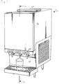
- Fig. 1 is a perspective of a dispenser which can dispense three different juices;
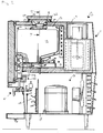
- Fig. 2 is a cross-sectional side view taken along line 2-2 of Fig. 1;
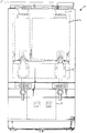
- Fig. 3 is a partially broken away front view of the dispenser of Fig. 1;
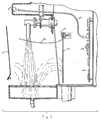
- Fig. 4 is an exploded partial cross-sectional view taken along the line 4-4 of Fig. 3;
- Fig. 5 is a partial cross-sectional front view taken along line 5-5 of Fig. 2;
- Fig. 6 is an exploded bottom perspective view of a top fill cover assembly;
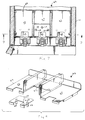
- Fig. 7 is a partial cross-sectional top plan view taken along line 9-9 of Fig. 3;
- Fig. 8 is an exploded perspective view of the tray assembly;
- Fig. 9 is a cross-sectional view taken along line 9-9 of Fig. 7;
- Fig. 10 is a cross-sectional view taken along line 10-10 of Fig. 9; and
- Fig. 11 is a front view of the beverage dispenser according to an alternative embodiment.
- The present invention relates to a beverage dispenser which combines a concentrated syrup with fresh water to provide a cool drink. Referring to Fig. 2, the
beverage dispenser 10 has a refrigeratedcompartment 12 for holding acontainer 14 with the syrup, a refrigerated mechanism 11 for cooling the water which is provided from an external line (not shown) to the dispenser, and arefrigeration system 13 mounted on thebase 15 ofcabinet 17.Compartment 12 has acooling system 19 with coils and a fan for circulating cool air withincompartment 12. The cool water and the syrup are each provided to amixing valve 21 from a pump 23. Controls allow the user then to dispense the beverage from the mixing valve through a sprout. The beverage dispenser is controlled by microprocessor controls on acircuit board 100 in the interior of the dispenser. - The top fill arrangement is illustrated and described in connection with Figs. 1, 2, 3, 5, and 6.
Compartment 12 can hold two, three, ormore containers 14, as desired. Eachcontainer 14 has an opening in the top which is aligned under an opening 18 in the refrigerated compartment. Aplastic funnel 20 is provided in eachopening 18 and extends into opening 16 in eachcontainer 14. -
Funnels 20 are covered by acover 22 which is shown in more detail in an exploded view in Fig. 6.Cover 22 has a top panel 24 which has ametal skin 26 andinsulation 28. Around the perimeter of the metal skin are rivet holes 30.Rubber seal 32 is positioned over the metal skin, and aplastic panel 34 is pressed inside the interior of theseal 32. The plastic panel, seal, and metal skin are held together with plastic snaps 36, each of which includes a center pin 38 and a splitleg engaging mechanism 40.Lid 22 is held onto the top surface of the dispenser housing with amagnetic strip 50. The plastic panel can be removed for cleaning if desired. - Referring to Fig. 5 in particular, funnel 20 passes through cabinet 11 and into
refrigerated compartment 12. The funnel is surrounded by layers including ametal ring 44, aplastic sleeve 46, and a plasticinner housing wall 47. This three layer assembly is held together with screws 49. No rubber gasket is provided, so the funnels and top openings are easier to clean. The screws are positioned in a recessed portion in the cabinet and do not protrude outside the cabinet at the top surface. - Referring to Figs. 7-10, a syrup sensing system is provided for a dispenser which may have three or
more syrup containers 14 in the refrigerator compartment simultaneously. Electrodes 60a-60f and the circuitry coupled to the electrodes for sensing the out-of-syrup condition are generally similar to the electrodes shown and described in the incorporated reissue patent. - Referring in particular to Figs. 7 and 8,
tray assembly 62 has twotrays tray 64 hashorizontal support portions support portion 67 for the center container.Support portion 67 is about half the size ofsupport portions Tray 64 surroundssmaller tray 66 on three sides.Tray 66 is supported byposts 68 which have electrical contacts.Trays sections 69 for receiving the mixing and dispensing values. - Referring in particular to Fig. 9, each
container end container 72, a voltage is provided fromlead 78 through electrode 60a and to electrodes 88a and 88b. These electrodes are coupled to groundedlead 80 throughtray 64. Since the level ofsyrup 76 is above the height of electrodes 60a and 60b, a noninfinite impedance is detected, which indicates that there is no out-of-syrup condition. With respect tocontainer 74, however, the conductive path fromlead 82 fromlead 84 is broken when the level ofsyrup 86 falls below the level of electrodes 60e-60f. Consequently, circuitry (not shown) indicates that an out-of-syrup condition exists, and a visible indication (not shown), such as a flashing light, is provided on the housing to notify a user. The user can then add syrup through the funnels. - The current flows along a different conductive path in
container 73. Leads 70 provide a voltage totray portion 66, and, in turn, to electrodes 88c and 88d. The conductive path extends through syrup 77 to electrodes 60c and 60d. If, as is true for thecenter container 73, the syrup is below the vertical level of electrodes 60c and 60d, the infinite impedance causes circuits (not shown) to indicate the out-of-syrup condition to a user, as described above. - Access to system controls is provided as illustrated in Figs. 2-4. The controls are controlled by a microprocessor on a
circuit board 100. The circuit board is connected, throughcable 102, tocontrols 104 which are visible to a user on the front of the dispenser (Fig. 1).Controls 104 allow a user to select a large size drink, small size drink, or continuous monitored flow. In addition, the circuitry on thecircuit board 100 has a learning mode in which a user can set any level for a small glass or a large glass. A user positions a glass and fills it to a desired level. This level is entered as a particular size, and is provided whenever the particular size is selected. - Some of the controls are programmable and controllable on the exterior of the cabinet, but other controls, such as
potentiometers 108, can be adjusted on the circuit board by a user. Potentiometers 103 can be adjusted for each spout to change the ratio of the water to syrup mixture. A removablesplash plate cover 110 protects the circuitry during normal operation. When desired, however,plate 110 can be removed and the circuitry can be observed through aclear plastic shield 112. This shield is positioned vertically and is coupled to the frame of the cabinet withscrews 114 across the top of the shield. This arrangement allows a user to easily lift the shield to a raised position 116 (Fig. 4). The shield allows a user to observe the circuit board during diagnostics, while still providing protection from liquid to the interior of the dispenser. - Referring to Fig. 2, pump 120 is provided for each container, and has
blades 122 which are turned bymotor 124. The blades turn in housing 126 which also hasconduits 128 with syrup. Whilemotor 124 is outside the refrigerated compartment, according to the present invention, housing 126 of the pump withblades 122 are provided in a dropped portion in the refrigerated compartment. Thus the syrup which is in the pump is kept refrigerated. If the pump is not operated for a long period of time, the syrup inconduits 128 remains cool. - Referring to Fig. 11, the refrigerated compartment can hold two containers with different sizes. In this embodiment, funnels 114, the arrangement of pump 116, and the shield 118 are similar to those described in the previous embodiment. The tray assembly is different because of the two containers.
- The tray assembly may be similar if desired, and if there are three containers, including one which is different from the others, the tray assembly according to the present invention may be used.
- Having described embodiments of the present invention, it should become apparent that other changes and modifications may be made without departing from the scope of the invention as defined by the appended claims.
Claims (12)
- A beverage dispenser having a refrigerated compartment for holding more than two containers for holding syrup, each container having a plurality of electrodes, the dispenser comprising:
an electrically conductive tray assembly having
a first horizontal portion for supporting a first container, and
a second horizontal portion for supporting a second container, wherein the first and second portions are electrically insulated from each other,
the second container having a first electrode for contacting the first portion and a second electrode for contacting the second portion; and
means for providing an electrical signal to one of the first and second electrodes. - The dispenser of claim 1 wherein the container has a bottom portion and side portions, wherein the first electrode is in one of the side portions and the second electrode is in the bottom portion.
- The dispenser of claim 2 wherein the first support has a horizontal portion for supporting a container and a vertical portion electrically connected to the horizontal portion, the vertical portion extending intermediate the first and second containers.
- A beverage dispenser comprising:
a refrigerated compartment for holding containers of syrup;
means for providing water;
means for combining the syrup from the container and the water from the providing means;
a pump coupled to the container for pumping syrup from the container to the combining means, the pump having a conduit passing therethrough, and a housing for enclosing the conduit, wherein the housing is enclosed within the refrigerated compartment. - The dispenser of claim 4 wherein the pump has a motor which is external to the refrigerated compartment.
- A beverage dispenser comprising:
a cabinet having a frame and a removable plate;
a circuit board mounted to the frame and enclosed within the cabinet;
a shield coupled to the frame intermediate the circuit board and the removable plate, the shield comprising a material which is waterproof and at least partially transparent. - The dispenser of claim 6 wherein the circuit board is mounted vertically.
- The dispenser of claim 6 wherein the shield includes a vertically oriented plastic sheet coupled to the frame, the sheet having a top portion and a bottom portion, the top portion of the sheet being coupled to the frame, the bottom portion being movable relative to the frame.
- A beverage dispenser for combining syrup and water and for dispensing a combination of water and syrup as a beverage, the dispenser comprising:
a cabinet having a top wall with an opening;
a refrigerated compartment within the cabinet for holding a container of syrup, the container having an opening which is near the opening in the cabinet when the container is positioned in the refrigerated compartment;
a removable, replaceable funnel for extending through the opening in the cabinet and through the opening in the container, the funnel having a gasket-free interference fit with the opening in the cabinet. - The dispenser of claim 9 further comprising a lid for covering the funnel, the lid having a magnet for attraction to the cabinet.
- The dispenser of claim 10 wherein the lid has a removable plastic plate adjacent the funnel when the lid is positioned over the funnel.
- The dispenser of claim 9 further comprising a lid, the lid having a periphery with a rim and a horizontal plate adjacent the funnel when the funnel is positioned in the opening in the cabinet, the plate having an area similar to the area of the lid.
Applications Claiming Priority (2)
| Application Number | Priority Date | Filing Date | Title |
|---|---|---|---|
| US08/151,069 US5490614A (en) | 1993-11-10 | 1993-11-10 | Beverage dispenser tray assembly |
| US151069 | 1993-11-10 |
Publications (2)
| Publication Number | Publication Date |
|---|---|
| EP0652179A2 true EP0652179A2 (en) | 1995-05-10 |
| EP0652179A3 EP0652179A3 (en) | 1995-07-05 |
Family
ID=22537197
Family Applications (1)
| Application Number | Title | Priority Date | Filing Date |
|---|---|---|---|
| EP94410097A Ceased EP0652179A3 (en) | 1993-11-10 | 1994-11-08 | Beverage dispenser. |
Country Status (2)
| Country | Link |
|---|---|
| US (2) | US5490614A (en) |
| EP (1) | EP0652179A3 (en) |
Cited By (2)
| Publication number | Priority date | Publication date | Assignee | Title |
|---|---|---|---|---|
| GB2338558A (en) * | 1998-06-17 | 1999-12-22 | Isoworth Uk Ltd | Drink dispenser, concentrate detector and concentrate container |
| EP2562130A1 (en) * | 2004-04-02 | 2013-02-27 | Strauss Water Ltd | Water dispenser with pivoted spill collector |
Families Citing this family (41)
| Publication number | Priority date | Publication date | Assignee | Title |
|---|---|---|---|---|
| US5967371A (en) * | 1996-01-18 | 1999-10-19 | Charles Wells Limited | Beverage dispensing apparatus |
| JP3588187B2 (en) * | 1996-04-02 | 2004-11-10 | 三洋電機株式会社 | Combined beverage dispenser |
| US5664436A (en) * | 1996-04-29 | 1997-09-09 | Lancer Corporation | Component configuration for enhancing dispenser serviceability |
| KR970073663A (en) * | 1996-05-25 | 1997-12-10 | 김광호 | Dehydrator of cold / warm water purifier |
| US5927553A (en) * | 1996-07-24 | 1999-07-27 | Bunn-O-Matic Coporation | Powdered beverage mixing and dispensing apparatus |
| US5782380A (en) * | 1996-09-27 | 1998-07-21 | Pure Fill Corporation | Water dispensing system |
| US5797519A (en) * | 1997-03-14 | 1998-08-25 | The Coca-Cola Company | Postmix beverage dispenser |
| US6095370A (en) * | 1997-12-18 | 2000-08-01 | Americlean Systems, Inc. | Encapsulated liquid dispensing device and method |
| US6123090A (en) * | 1998-03-17 | 2000-09-26 | Wescott; Daniel T. | Air conditioner condensation dispersement apparatus |
| USD440255S1 (en) | 1999-04-22 | 2001-04-10 | Glacier Water Systems, Inc. | Fluid dispensing apparatus |
| JP2001052256A (en) * | 1999-08-06 | 2001-02-23 | Sanyo Electric Co Ltd | Automatic cup type vending machine |
| US6751525B1 (en) | 2000-06-08 | 2004-06-15 | Beverage Works, Inc. | Beverage distribution and dispensing system and method |
| US7004355B1 (en) | 2000-06-08 | 2006-02-28 | Beverage Works, Inc. | Beverage dispensing apparatus having drink supply canister holder |
| US7083071B1 (en) | 2000-06-08 | 2006-08-01 | Beverage Works, Inc. | Drink supply canister for beverage dispensing apparatus |
| US7754025B1 (en) | 2000-06-08 | 2010-07-13 | Beverage Works, Inc. | Dishwasher having a door supply housing which holds dish washing supply for multiple wash cycles |
| US6449532B1 (en) | 2000-11-22 | 2002-09-10 | Gorham Nicol | Programmable beverage dispensing apparatus |
| WO2003035536A2 (en) * | 2001-10-19 | 2003-05-01 | Manitowoc Foodservice Companies, Inc. | Beverage dispenser with integral ice maker |
| US6488179B1 (en) * | 2001-11-12 | 2002-12-03 | Zoran Vujicic | Disposable aseptic cassette with control center |
| US6588632B1 (en) | 2001-11-20 | 2003-07-08 | Gorham Nicol | Programmable beverage dispensing apparatus |
| USD487208S1 (en) | 2002-11-12 | 2004-03-02 | Bunn-O-Matic Corporation | Liquid beverage machine |
| US7086566B2 (en) * | 2003-07-03 | 2006-08-08 | Creamiser Products Corporation | Under counter dispenser |
| US7210601B2 (en) * | 2004-06-04 | 2007-05-01 | Whirlpool Corporation | Variable flow water dispenser for refrigerator freezers |
| US7624895B2 (en) * | 2005-02-17 | 2009-12-01 | Lancer Partnership, Ltd. | Tower dispenser |
| US20070009695A1 (en) * | 2005-07-07 | 2007-01-11 | Lancer Partnership, Ltd. | Method and apparatus for a mold barrier |
| US7866508B2 (en) * | 2005-09-19 | 2011-01-11 | JMF Group LLC | Beverage dispensing system and method |
| US20070290001A1 (en) * | 2006-06-17 | 2007-12-20 | James Daniel Bachrach | Portable beverage dispensing apparatus |
| US20080276639A1 (en) * | 2007-05-10 | 2008-11-13 | Stoddard Robert J | Computer cooling system |
| US8152024B2 (en) * | 2008-03-20 | 2012-04-10 | Imi Cornelius Inc. | Apparatus for attaching a drip tray to a beverage dispenser |
| KR100985384B1 (en) * | 2008-06-27 | 2010-10-05 | 주식회사 경동네트웍 | Method for controlling hot water temperature when using low flow hot water in hot water supply system |
| US8459176B2 (en) * | 2008-12-08 | 2013-06-11 | Enodis Corporation | Integrated method and system for dispensing and blending/mixing beverage ingredients |
| WO2011050005A2 (en) | 2009-10-19 | 2011-04-28 | Bevtech Incorporated | Gas line leakage monitor for beverage dispensing system preventing unintended environmental discharge |
| US8844768B2 (en) | 2011-06-27 | 2014-09-30 | Prince Castle LLC | Liquid dispenser with storage tanks |
| US20130248538A1 (en) | 2012-03-23 | 2013-09-26 | Prince Castle, LLC | Holding Tank With Internally Reinforced Sidewalls and Liquid Dispenser Using Same |
| JP6097027B2 (en) * | 2012-07-09 | 2017-03-15 | サンデンホールディングス株式会社 | Beverage supply equipment |
| USD713931S1 (en) | 2013-01-09 | 2014-09-23 | Central Garden & Pet Company | Sprayer |
| CN105813974B (en) * | 2013-12-26 | 2019-12-10 | 可口可乐公司 | Cooling system for a beverage dispenser and method for maintaining a cooling system |
| CA3022100A1 (en) | 2016-04-06 | 2017-10-12 | Font Fine Wine Pty Ltd | Beverage dispenser |
| CN113168063A (en) * | 2018-12-12 | 2021-07-23 | 伊英克公司 | Edible electrode and use in electro-optic displays |
| KR102752449B1 (en) | 2020-03-12 | 2025-01-10 | 엘지파루크 주식회사 | Dispenser |
| US12304799B2 (en) * | 2021-10-01 | 2025-05-20 | Haier Us Appliance Solutions, Inc. | Beverage-dispensing appliance having a chilled carbonator |
| US11618665B1 (en) * | 2021-10-04 | 2023-04-04 | Haier Us Appliance Solutions, Inc. | Beverage-dispensing appliance having a signal shield |
Family Cites Families (11)
| Publication number | Priority date | Publication date | Assignee | Title |
|---|---|---|---|---|
| US4732297A (en) * | 1983-10-26 | 1988-03-22 | Lancer Corporation | Liquid level detector apparatus for a concentrate dispenser tank |
| US4645095A (en) * | 1984-03-19 | 1987-02-24 | Jet Spray Corp. | Syrup sensor for dispensing machine |
| US4728005A (en) * | 1984-03-19 | 1988-03-01 | Jet Spray Corp. | Self-fill system |
| US4717045A (en) * | 1984-03-19 | 1988-01-05 | Jet Spray Corp. | Syrup sensor for dispensing machine |
| EP0161042B1 (en) * | 1984-03-19 | 1989-05-10 | Jet Spray Corp | Self-fill system |
| US4610145A (en) * | 1984-09-21 | 1986-09-09 | Arzberger William A | Post mix fruit juice dispenser |
| USRE33943E (en) * | 1984-09-21 | 1992-06-02 | Jet Spray Corp. | Post mix fruit juice dispenser |
| US4856676A (en) * | 1987-09-03 | 1989-08-15 | Jet Spray Corp. | Post mix dispenser |
| US4795061A (en) * | 1987-09-23 | 1989-01-03 | Chilly-Willee Products Div. Of Gross-Given Manufacturing Company | Apparatus for providing water and syrup in a predetermined ratio to a beverage dispenser |
| US5303846A (en) * | 1990-09-17 | 1994-04-19 | Abcc/Techcorp. | Method and apparatus for generating and dispensing flavoring syrup in a post mix system |
| US5367423A (en) * | 1991-09-27 | 1994-11-22 | Phillips Bryant L | Insertable protective device for VCRs |
-
1993
- 1993-11-10 US US08/151,069 patent/US5490614A/en not_active Expired - Lifetime
-
1994
- 1994-11-08 EP EP94410097A patent/EP0652179A3/en not_active Ceased
-
1995
- 1995-03-23 US US08/409,326 patent/US5492250A/en not_active Expired - Fee Related
Cited By (2)
| Publication number | Priority date | Publication date | Assignee | Title |
|---|---|---|---|---|
| GB2338558A (en) * | 1998-06-17 | 1999-12-22 | Isoworth Uk Ltd | Drink dispenser, concentrate detector and concentrate container |
| EP2562130A1 (en) * | 2004-04-02 | 2013-02-27 | Strauss Water Ltd | Water dispenser with pivoted spill collector |
Also Published As
| Publication number | Publication date |
|---|---|
| US5492250A (en) | 1996-02-20 |
| US5490614A (en) | 1996-02-13 |
| EP0652179A3 (en) | 1995-07-05 |
Similar Documents
| Publication | Publication Date | Title |
|---|---|---|
| US5490614A (en) | Beverage dispenser tray assembly | |
| US4610145A (en) | Post mix fruit juice dispenser | |
| US6705356B2 (en) | Touchless automatic fiber optic beverage/ice dispenser | |
| KR970007236B1 (en) | Portable post-mix beverage dispenser | |
| KR100256424B1 (en) | Product identification system for beverage dispenser | |
| US7980422B2 (en) | Portable beverage dispenser with electronic beverage characteristic display and method | |
| US5562003A (en) | Apparatus for detecting the level of a liquid in a tank | |
| CA1059471A (en) | Three drink gravity dispenser for cool beverages | |
| US4544084A (en) | Beverage dispenser | |
| CA2141501C (en) | Beverage dispenser | |
| US3927802A (en) | Manual fill hot beverage dispenser | |
| US5967371A (en) | Beverage dispensing apparatus | |
| US4496080A (en) | Automatic household beverage dispenser | |
| US5833096A (en) | Water dispenser | |
| USRE33943E (en) | Post mix fruit juice dispenser | |
| EP2355667B1 (en) | An integrated method and system for dispensing beverage ingredients | |
| EP0306265A2 (en) | Post mix dispenser | |
| US3333438A (en) | Water cooler and dispenser having a replaceable reservoir | |
| US5144543A (en) | Domestic appliance having electrically isolated input control circuitry | |
| US6158235A (en) | Evaporator coil | |
| EP0823397B1 (en) | Water dispenser | |
| US5263334A (en) | Food service counter of the ice storage type | |
| GB2101088A (en) | Beverage-dispensing machine | |
| US4732297A (en) | Liquid level detector apparatus for a concentrate dispenser tank | |
| US20030071055A1 (en) | Automatic fill system for a beverage dispenser |
Legal Events
| Date | Code | Title | Description |
|---|---|---|---|
| PUAI | Public reference made under article 153(3) epc to a published international application that has entered the european phase |
Free format text: ORIGINAL CODE: 0009012 |
|
| AK | Designated contracting states |
Kind code of ref document: A2 Designated state(s): BE DE FR GB IT NL SE |
|
| PUAL | Search report despatched |
Free format text: ORIGINAL CODE: 0009013 |
|
| AK | Designated contracting states |
Kind code of ref document: A3 Designated state(s): BE DE FR GB IT NL SE |
|
| 17P | Request for examination filed |
Effective date: 19951222 |
|
| RIN1 | Information on inventor provided before grant (corrected) |
Inventor name: SARDYNSKI, GARY F. |
|
| 17Q | First examination report despatched |
Effective date: 19960229 |
|
| GRAG | Despatch of communication of intention to grant |
Free format text: ORIGINAL CODE: EPIDOS AGRA |
|
| STAA | Information on the status of an ep patent application or granted ep patent |
Free format text: STATUS: THE APPLICATION HAS BEEN REFUSED |
|
| 18R | Application refused |
Effective date: 19970124 |