EP0651963B1 - Cellule d'extraction de type centrifuge pour une machine de préparation de boisson chaude comportant un joint d'étanchéité déformable - Google Patents
Cellule d'extraction de type centrifuge pour une machine de préparation de boisson chaude comportant un joint d'étanchéité déformable Download PDFInfo
- Publication number
- EP0651963B1 EP0651963B1 EP19940420310 EP94420310A EP0651963B1 EP 0651963 B1 EP0651963 B1 EP 0651963B1 EP 19940420310 EP19940420310 EP 19940420310 EP 94420310 A EP94420310 A EP 94420310A EP 0651963 B1 EP0651963 B1 EP 0651963B1
- Authority
- EP
- European Patent Office
- Prior art keywords
- gasket
- unit according
- extractor unit
- groove
- drum
- Prior art date
- Legal status (The legal status is an assumption and is not a legal conclusion. Google has not performed a legal analysis and makes no representation as to the accuracy of the status listed.)
- Expired - Lifetime
Links
- 238000000605 extraction Methods 0.000 title description 35
- 235000013361 beverage Nutrition 0.000 title 1
- 238000001914 filtration Methods 0.000 claims description 26
- 235000013353 coffee beverage Nutrition 0.000 claims description 22
- 238000007789 sealing Methods 0.000 claims description 17
- 230000006835 compression Effects 0.000 claims description 15
- 238000007906 compression Methods 0.000 claims description 15
- 239000007788 liquid Substances 0.000 claims description 12
- 239000000203 mixture Substances 0.000 claims description 10
- 235000012171 hot beverage Nutrition 0.000 claims description 8
- XLYOFNOQVPJJNP-UHFFFAOYSA-N water Substances O XLYOFNOQVPJJNP-UHFFFAOYSA-N 0.000 claims description 5
- 239000000463 material Substances 0.000 claims description 4
- 229920001296 polysiloxane Polymers 0.000 claims description 2
- 230000002093 peripheral effect Effects 0.000 claims 2
- 239000006260 foam Substances 0.000 description 20
- 238000004519 manufacturing process Methods 0.000 description 6
- 238000002360 preparation method Methods 0.000 description 4
- 235000015114 espresso Nutrition 0.000 description 3
- 239000000706 filtrate Substances 0.000 description 3
- 230000002045 lasting effect Effects 0.000 description 3
- 238000000034 method Methods 0.000 description 3
- 238000005119 centrifugation Methods 0.000 description 2
- 238000010276 construction Methods 0.000 description 2
- 210000005069 ears Anatomy 0.000 description 2
- 230000000694 effects Effects 0.000 description 2
- 239000012530 fluid Substances 0.000 description 2
- 238000003801 milling Methods 0.000 description 2
- 241001122767 Theaceae Species 0.000 description 1
- 230000001154 acute effect Effects 0.000 description 1
- 125000003118 aryl group Chemical group 0.000 description 1
- 230000033228 biological regulation Effects 0.000 description 1
- 230000015572 biosynthetic process Effects 0.000 description 1
- 230000015556 catabolic process Effects 0.000 description 1
- 230000007423 decrease Effects 0.000 description 1
- 230000003247 decreasing effect Effects 0.000 description 1
- 238000006731 degradation reaction Methods 0.000 description 1
- 230000001419 dependent effect Effects 0.000 description 1
- 238000013461 design Methods 0.000 description 1
- 230000000977 initiatory effect Effects 0.000 description 1
- 238000012986 modification Methods 0.000 description 1
- 230000004048 modification Effects 0.000 description 1
- 150000002825 nitriles Chemical class 0.000 description 1
- 230000002441 reversible effect Effects 0.000 description 1
- 230000003068 static effect Effects 0.000 description 1
- 238000012549 training Methods 0.000 description 1
- 238000013519 translation Methods 0.000 description 1
Images

Classifications
-
- B—PERFORMING OPERATIONS; TRANSPORTING
- B04—CENTRIFUGAL APPARATUS OR MACHINES FOR CARRYING-OUT PHYSICAL OR CHEMICAL PROCESSES
- B04B—CENTRIFUGES
- B04B1/00—Centrifuges with rotary bowls provided with solid jackets for separating predominantly liquid mixtures with or without solid particles
- B04B1/10—Centrifuges with rotary bowls provided with solid jackets for separating predominantly liquid mixtures with or without solid particles with discharging outlets in the plane of the maximum diameter of the bowl
- B04B1/14—Centrifuges with rotary bowls provided with solid jackets for separating predominantly liquid mixtures with or without solid particles with discharging outlets in the plane of the maximum diameter of the bowl with periodical discharge
- B04B1/16—Centrifuges with rotary bowls provided with solid jackets for separating predominantly liquid mixtures with or without solid particles with discharging outlets in the plane of the maximum diameter of the bowl with periodical discharge with discharging outlets controlled by the rotational speed of the bowl
-
- A—HUMAN NECESSITIES
- A47—FURNITURE; DOMESTIC ARTICLES OR APPLIANCES; COFFEE MILLS; SPICE MILLS; SUCTION CLEANERS IN GENERAL
- A47J—KITCHEN EQUIPMENT; COFFEE MILLS; SPICE MILLS; APPARATUS FOR MAKING BEVERAGES
- A47J31/00—Apparatus for making beverages
- A47J31/22—Centrifuges for producing filtered coffee
Definitions
- the present invention relates to the field general technique for preparing hot drinks, and including coffee, from devices in which the hot drink is obtained by passing a liquid to the touch of an aromatic grind.
- the present invention relates to a cell centrifugal type extraction machine preparation of hot drink, preferably a machine coffee, comprising a ground coffee drum on which is tightly attached via a sealing means, a cover provided with an orifice liquid supply, said cell comprising also a means of filtration.
- centrifugal coffee machines therefore present a series of limitations as to their possibilities to supply a significant and sustainable quantity foam.
- the extraction cell formed a collecting drum to which is attached using locking means and sealing means, a cover delimiting with the drum a collecting volume of grind and hot water.
- the filtration of the water-milling-air mixture is provided by means of filtration consisting of a series of radial grooves distributed at the periphery of the extraction cell and formed between the cover and drum.
- the centrifugal coffee maker has outside the extraction cell a wall deflector against which the filtrate from the grooves radials is projected at an acute angle. The conjunction of projection angle, rotation speed and receptor wall is responsible for the formation of a certain amount of foam in the coffee.
- This construction requires good precision in the geometry of the assembly, in particular as regards relates to the surfaces of the base of the cone and of the spring disc coming in contact. This construction presents the disadvantage of being very sensitive to the tolerances of manufacturing.
- Document DE-A-35 29 053 discloses a coffee machine with a type extraction cell centrifugal with a seal arranged between the drum and the cover of said cell, in which the drum and the cover are mounted on an axis and are movable in translation with respect to each other. In a first position, the seal seals the cell. In a second position, the seal lets the liquid through filtered by an annular filtration slot constituted by two facing walls belonging to the drum and the lid.
- the seal of this device has only a role sealing and has no filtration action. By elsewhere, this device requires the intervention of the user to switch from the brewing position to the filtration position.
- GB-A-969,179 describes a method for control the outlet of the mud contained in a rotary centrifuge.
- a seal mounted in a closed throat an evacuation channel. When the centrifugal force exceeds one certain threshold, the deformation of the joint due to pressure exerted releases the passage of mud.
- a device designed according to this principle works in all or nothing and does not exercise filtration action. In particular, this method does not give no indication to separate the coffee from the non part liquid of the mixture.
- the object of the present invention is to consequence to remedy the various drawbacks listed above and to make an extraction cell preferably adaptable to a hot drink machine type centrifugal, and capable of producing a significant and lasting amount of foam using particularly simple and effective means.
- Another object of the invention is to provide a extraction cell capable of supplying a quantity appreciable and durable foam whatever variations in cell rotation speed extraction.
- a centrifugal type extraction cell to a hot drink preparation machine comprising a milling collecting drum to which is attached sealingly, by a sealing means, a cover provided with a liquid supply port, and means filtration, the filtration means and the means sealing consisting of at least one seal deformable, said seal having properties of deformation, and being mounted so as to ensure below of a preset operating pressure prevailing in the cell, the sealing of the latter, and beyond said pressure, filtration of the grind-liquid mixture by deformation of the seal, characterized in that the seal deformable is interposed in a groove between the drum and lid.
- the centrifugal extraction cell shown in the Figure 1 is formed by a drum 1 on which is attached a cover 2 defining with the drum 1, an internal volume 3 receiving and collecting ground coffee and water hot.
- the extraction cell preferably defines a body main of revolution around a main axis x-x ', with respect to which the cell is rotatably mounted via a non-training system shown in the figures.
- the drum 1 has a bottom 4 and a side wall 5 preferably circular, defining the outer envelope of said drum.
- the side wall 5 is extended at its lower part by a skirt 6 enveloping the bottom 4.
- the bottom 4 consists of a central zone 7 in cone shape whose apex is located on the axis x-x 'and facing the cover 2 so as to constitute a cone returning.
- the central zone 7 is connected to the side wall 5, from the large lower base of the cone by a annular wall 8 substantially forming a straight die with the envelope of said cone.
- the upper part of the side wall has an external shoulder 9 bordering all or part of the periphery of the side wall 5.
- the external shoulder 9 extends to the upper part of the side wall 5 by a rib 10 delimiting an upper face 10a and two lateral sides respectively internal 10b and external 10c. ( Figures 2 and 4 to 6).
- the cover 2 is in the form of a body of revolution around the axis x-x ', comprising a hole central 12 through which hot water can be admitted into the extraction cell.
- the cover 2 is intended to be attached and locked on the drum 1.
- the cover 2 is delimited by an external envelope 13 extending substantially along the generatrices of the skirt 6, said envelope being provided with an external collar 14 internally defining inclined ramps 14a.
- the profile of the inclined ramps is intended to cooperate with the outer shoulder 9 so as to form a means of known lock, bayonet type, allowing lock, by rotation around the axis x-x ', the cover 2 on the drum 1. It is also possible to reverse the mounting, and realize the inclined ramps 14a on the drum 1.
- the cover 2 has a conformation and a profile adapted to that of drum 1, and it has a groove 15 extending substantially around the periphery of said cover and formed between the terminal edge 13a of the outer casing 13 and an inclined annular wall 16, for example of the order of 5 to 8 ° with respect to the x-x 'axis, extending along a internal radial direction the external envelope 13 from an area above the edge 13a.
- the throat 15 extends preferably over the entire periphery of the cover 2 and has a cross section similar to a preferably quadrilateral square or rectangle.
- the groove 15 defines an upper wall 15a and two opposite side faces, respectively internal 15b and external 15c ( Figures 4 to 6).
- the throat 15 is intended to allow the partial introduction of the rib 10, up to in a stop position such as in the position of locking the cover 2 on the drum 1, a space annular 19 of determined cross section "s" is created between the upper face 10a and the walls of the groove 15.
- the cross section "s" is for example square or preferably rectangular.
- the stop position is obtained by means of compression control 50, which will be described later in detail.
- the width of the upper wall 15a is greater than that of the upper face 10a so as to be able to define between face 10b and wall 15b on the one hand, and face 10c and the wall 15c on the other hand, flow zones annulars, respectively an internal zone 20 and a zone external 21.
- the annular space 19 is intended to receive a deformable joint 25 made of all materials having good deformation properties, for example from of a silicone material or of NBR (Nitrile) type.
- the seal 25 is intended to ensure the seal between the internal volume 3 and the outside of the cell.
- the seal 25 is held in place against the bottom of the groove 15 by a compression means integral with the drum 1 and in this case by the upper face 10a of the rib 10 and its compression is controlled by a stop element mechanical 53 of the control means 50 interposed between the drum 1 and cover 2.
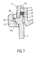
- the element of the mechanical stop is preferably formed, as shown in Figure 7, by one or more stops 53 integral with the cover 2 and formed in or on shaped hooking ears 52 to engage the inclined ramps 14a made at the periphery of the drum 1 and compress the seal 25 in a preset compression range.
- the compression control means 50 includes six stops 53 associated with an equal number of ears attachment 52 and inclined ramps 14a.
- each inclined ramp 14a is of the order of 5 ° and allows, for each relative rotation of the drum 1 and the cover 2 corresponding to a 1 mm projection of the ear (s) attachment 52 on the associated inclined ramp or ramps, a axial compression of the seal 25 of the order of about 0.1 mm.
- the presence of the abutment (s) 53, substantially in the middle of the hooking lug (s) 52 blocks the locking and limits the tightening torque of the seal 25 to a value of preset compression, variable depending on the nature, shape and the material of the seal 25, and for example at a maximum torque about 4.4 N ⁇ m for a cell with a diameter of 8 cm about.
- the deformable seal 25, of a average section of about 2.6 mm constitutes not only the sealing means, but also the filtration means of the extraction cell.
- the deformable seal 25 interposed between the drum 1 and the cover 2 has deformation properties allowing it to ensure for a level of compression fixed and determined by means of control 50 below an operating pressure pre-established reigning in the cell, the tightness of this last, and beyond said pressure the filtration of the grind-liquid-air mixture by deformation of said seal.
- the hardness of the deformable joint 25 is important and will be between 50 and 90 shore A and preferably between 65 and 75 shore A, the average value being 70 shore A.
- the cross section of the deformable joint 25 could for example be circular, as shown in Figures 2 to 5, or for example square or rectangular.
- the seal 25 can assume a double sealing and filtration function. Indeed during locking of the cover 2 on the drum 1, the rib 10 slightly compress the seal 25 placed in the groove 15 and occupying at least part of the annular space 19. Manufacturing clearances and compression tolerances can be usefully caught up by the bayonet lock and control means 50, similarly wear of the seal.
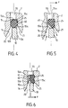
- the seal 25 In this sealing position, and up to a preset internal operating pressure corresponding to a certain speed of rotation of the extraction cell, the seal 25 always assumes a sealing function preventing water-milling-air mixture from go from inside the extraction cell to outside. So, as shown for example in Figure 4 the mixture is maintained in the internal zone 20 without being able to reach the external zone 21. After a certain latency time corresponding to the achievement by the cell of its average speed of rotation, the combination of force centrifugal F and the pressure exerted by the mixture, allows at the joint 25 to gradually come to occupy the position of limit filtration shown in Figure 5. In this position the seal 25 is applied and pressed against the external wall 15c, letting the liquid pass from the internal zone 20 to in the annular space 19.
- the latter After reaching the pressure critical of operation necessary for the deformation of the joint 25, the latter undergoes additional deformation allowing partial creep in the external zone 21 such that shown in Figure 6, such a deformation allowing a filtration of the mixture between the upper face 10a and the seal 25.
- the filtrate is evacuated and flows by the external zone 21 outside the cell.
- the invention thus makes it possible, using means particularly simple and inexpensive, since a double function is assumed by a single piece, to obtain a coffee espresso with abundant and lasting foam. It is also important to note that whatever the variations of the rotation speed of the extraction cell, the filtration takes place independently of the latter, since filtration is directly linked to the properties of deformation of the joint for which control is assured. As example only, practical operating pressure can be obtained for cell rotation the diameter of which is approximately 8 cm, of the order from 4500 to 12500 rpm, the average being around 7000 rpm.
- the cell extraction can include several deformable seals 25 forming defined sectors at the periphery of the cell.
- the cover 2 can be provided with a series of perforations 55 formed in the groove 15 from the upper wall 15a and relating the annular space 19 to the outside of the cell.
- the perforations 55 are of circular section and distributed regularly at the periphery of the cell, and for example six in number. They allow proper positioning of the seal 25 at the bottom of the groove 15 while ensuring an escape of the trapped air between the seal 25 and the upper wall 15a. Tightening the seal 25 is thus perfectly controlled as is the filtration, and avoids the appearance of a phenomenon of seal 25 floating.
- Holding seal 25 in place can also be improved by the presence of two gadroons annular 60 ( Figure 4) made on either side of the joint 25 from the walls 15b, 15c to compress laterally said joint 25 under an initial prestress and favor her outfit.
- the perforations 55 also provide (FIGS. 5 to 7) during rotation and during filtration, the internal pressure regulation allowing fluid escape helping to maintain a pressure of constant operation and deformation of the joint 25.
- the perforations 55 are made so that their axis of symmetry does not coincide with said plane, and either on the contrary slightly offset radially inwards of the cell.
- This realization allows to spare a channel overpressure 61 extending internally each perforation 55 to open into the throat 25 and into particular in internal channel 20 and communicate as well with the latter.
- the extraction cell comprises by example six perforations 55
- each of them is associated with an overpressure channel 61.
- the function essential of the overpressure channel (s) 61 is to keep internal operating pressure within range pressure, allowing and initiating a fluid escaping at a pressure slightly below that normally authorized by the mere presence of perforations 55 in the event of a temporary overload of the seal 25 (figure 6). Indeed, large increases in pressure can occur fleetingly during rotation of the cell and the seal 25 is then pressed against the wall 15c by centrifugal force and by liquid, and while partially extruding into the external channel 21, discovers the overpressure channels 61 sufficiently to allow the pressure to descend almost instantly.
- the overpressure channels 61 therefore help to increase the operational safety and reliability.
- the overpressure channels 61 can be independent of perforations 55.
Landscapes
- Engineering & Computer Science (AREA)
- Food Science & Technology (AREA)
- Apparatus For Making Beverages (AREA)
- Centrifugal Separators (AREA)
Description
- La figure 1 représente selon une coupe transversale, une vue générale d'une cellule d'extraction conforme à l'invention.
- La figure 2 représente selon une vue en coupe transversale, un détail de réalisation de l'invention selon une première variante de réalisation.
- La figure 3 montre selon une vue en coupe transversale un détail de réalisation d'une seconde variante de réalisation conforme à l'invention.
- Les figures 4, 5 et 6 représentent selon des vues en coupe transversale partielle des exemples de réalisation de cellules d'extraction conformes à l'invention, illustrant différentes positions susceptibles d'être prises par un joint d'étanchéité et de filtration conforme à l'invention.
- La figure 7 montre, selon une vue en coupe transversale partielle d'une cellule d'extraction en rotation, un détail de réalisation d'une version préférentielle de l'invention.
Claims (15)
- Cellule d'extraction de type centrifuge pour une machine de préparation de boisson chaude, comportant un tambour (1) collecteur de mouture sur lequel est rapporté de manière étanche, par un moyen d'étanchéité, un couvercle (2) pourvu d'un orifice d'alimentation (12) en liquide, et un moyen de filtration, le moyen de filtration et le moyen d'étanchéité étant constitués d'au moins un joint déformable (25), ledit joint (25) présentant des propriétés de déformation, et étant monté de manière à assurer en deçà d'une pression de fonctionnement préétablie régnant dans la cellule, l'étanchéité de cette dernière, et au delà de ladite pression, la filtration du mélange mouture-liquide par déformation du joint, caractérisée en ce que le joint déformable (25) est interposé dans une gorge (15) entre le tambour (1) et le couvercle (2).
- Cellule d'extraction selon la revendication 1, caractérisée en ce que le joint (25) est monté dans une plage de compression préétablie, par l'intermédiaire d'un moyen de contrôle de compression (50).
- Cellule d'extraction selon l'une des revendications 1 ou 2, caractérisée en ce que le moyen de contrôle de compression (50) est interposé entre le tambour (1) et le couvercle (2) et formé par un élément de butée mécanique (53).
- Cellule d'extraction selon la revendication 3 caractérisée en ce qu'elle comporte au moins un canal de surpression (61) ménagé intérieurement entre le joint (25) et la gorge (15).
- Cellule d'extraction selon l'une des revendications 1 à 4 caractérisée en ce que la gorge (15) est pourvue de perforations (55) s'étendant entre la paroi supérieure (15a) et l'extérieur de la cellule.
- Cellule d'extraction selon les revendications 4 et 5 caractérisée en ce que chaque canal de surpression (61) prolonge intérieurement la perforation (55) qui lui est associée du côté interne et débouche dans la gorge (15).
- Cellule d'extraction selon l'une des revendications 1 à 6 caractérisée en ce que la gorge (15) dans laquelle le joint (25) est disposé est ménagée dans le couvercle (2) ou le tambour (1) et présente une paroi supérieure (15a) s'étendant sensiblement radialement par rapport à l'axe de symétrie x-x' de la cellule.
- Cellule d'extraction selon la revendication 7 caractérisée en ce que la gorge (15) est ménagée dans la tranche périphérique du couvercle (2) et en ce que le joint (25) est maintenu en place contre la paroi supérieure (15a) par un moyen de compression (10) solidaire du tambour (1).
- Cellule d'extraction selon la revendication 8 caractérisée en ce que le moyen de compression forme une nervure (10) à la périphérie du tambour (1) délimitant une face supérieure (10a) en appui étanche contre le joint (25) et deux faces latérales (10b, 10c) chacune formant avec chaque paroi de la gorge (15) qui lui est associée une zone d'écoulement (20, 21) pour assurer respectivement l'arrivée du mélange mouture-eau et la sortie de la boisson après filtration entre le joint (25) et la face supérieure (10a).
- Cellule d'extraction selon l'une des revendications 1 à 9 caractérisée en ce que le joint (25) occupe dans sa position d'étanchéité jusqu'à 120 % de la section "s" correspondante de la gorge (15) et de préférence entre 110 % et 120 %.
- Cellule d'extraction selon l'une des revendications précédentes caractérisée en ce que le joint (25) est réalisé dans un matériau de préférence en matière siliconée ou en NBR, présentant une résistance shore A comprise entre 50 et 90, et de préférence entre 65 et 75.
- Cellule d'extraction selon l'une des revendications précédentes caractérisée en ce que le joint (25) et la gorge (15) s'étendent sur toute la circonférence de la cellule pour former un joint annulaire et une gorge périphérique.
- Cellule d'extraction selon l'une des revendications précédentes caractérisée en ce que le joint (25) est de section sensiblement circulaire, ou en forme de carré ou de rectangle.
- Machine à boisson chaude pourvue d'une cellule d'extraction conforme à l'une des revendications 1 à 13.
- Machine selon la revendication 14 caractérisée en ce qu'elle est constituée d'une machine à café centrifuge.
Applications Claiming Priority (2)
| Application Number | Priority Date | Filing Date | Title |
|---|---|---|---|
| FR9313606A FR2712163B1 (fr) | 1993-11-09 | 1993-11-09 | Cellule d'extraction de type centrifuge pour une machine de préparation de boisson chaude comportant un joint d'étanchéité déformable. |
| FR9313606 | 1993-11-09 |
Publications (2)
| Publication Number | Publication Date |
|---|---|
| EP0651963A1 EP0651963A1 (fr) | 1995-05-10 |
| EP0651963B1 true EP0651963B1 (fr) | 1998-01-21 |
Family
ID=9452864
Family Applications (1)
| Application Number | Title | Priority Date | Filing Date |
|---|---|---|---|
| EP19940420310 Expired - Lifetime EP0651963B1 (fr) | 1993-11-09 | 1994-11-09 | Cellule d'extraction de type centrifuge pour une machine de préparation de boisson chaude comportant un joint d'étanchéité déformable |
Country Status (4)
| Country | Link |
|---|---|
| EP (1) | EP0651963B1 (fr) |
| DE (1) | DE69408088T2 (fr) |
| ES (1) | ES2114155T3 (fr) |
| FR (1) | FR2712163B1 (fr) |
Cited By (7)
| Publication number | Priority date | Publication date | Assignee | Title |
|---|---|---|---|---|
| US8658232B2 (en) | 2009-08-28 | 2014-02-25 | Nestec S.A. | Capsule system for the preparation of beverages by centrifugation |
| US8813634B2 (en) | 2007-06-05 | 2014-08-26 | Nestec S.A. | Capsule for preparing a beverage or liquid food and system using brewing centrifugal force |
| US8986764B2 (en) | 2007-06-05 | 2015-03-24 | Nestec S.A. | Capsule and method for preparing a food liquid by centrifugation |
| US9162815B2 (en) | 2009-08-19 | 2015-10-20 | Nestec S.A. | Capsule for the preparation of a coffee extract having a structure facilitating perforation for injection of water |
| US9271598B2 (en) | 2007-06-05 | 2016-03-01 | Nestec S.A. | Method for preparing a food liquid contained in a capsule by centrifugation and device adapted for such method |
| US9434532B2 (en) | 2007-06-05 | 2016-09-06 | Nestec S.A. | Capsule for preparing a beverage or food liquid and system using brewing centrifugal force |
| US12696994B2 (en) | 2010-01-29 | 2026-08-04 | Societe Des Produits Nestle S.A. | Capsule and system for preparing a beverage by centrifugation in a beverage production device |
Families Citing this family (16)
| Publication number | Priority date | Publication date | Assignee | Title |
|---|---|---|---|---|
| DE4441026A1 (de) * | 1994-11-17 | 1996-05-23 | Bosch Siemens Hausgeraete | Zentrifugenfilter einer elektrischen Kaffeemaschine |
| US5935051A (en) * | 1997-08-29 | 1999-08-10 | Beckman Instruments, Inc. | Blood separation device |
| EP1876934B1 (fr) | 2005-04-22 | 2011-12-21 | Coffee Innovation Group B.V. | Dispositif destine a preparer le cafe |
| BRPI0812195B1 (pt) | 2007-06-05 | 2018-11-21 | Nestec Sa | cápsula de uso único para preparação de um líquido alimentício por centrifugação |
| DE602007008213D1 (de) | 2007-06-05 | 2010-09-16 | Nestec Sa | Verfahren zur Herstellung eines Getränks oder flüssigen Nahrungsmittels und System unter Verwendung von Brauzentrifugalkraft |
| JP5457455B2 (ja) * | 2008-09-02 | 2014-04-02 | ネステク ソシエテ アノニム | 遠心力を使用した制御型飲料製造装置 |
| WO2010026045A1 (fr) * | 2008-09-02 | 2010-03-11 | Nestec S.A. | Procédé de préparation par centrifugation d'un liquide alimentaire contenu dans une capsule et système conçu pour un tel procédé |
| US9095236B2 (en) | 2008-12-09 | 2015-08-04 | Nestec S.A. | Liquid food preparation system for preparing a liquid food by centrifugation |
| RU2527176C2 (ru) | 2008-12-09 | 2014-08-27 | Нестек С.А. | Капсула для приготовления напитка методом центрифугирования и устройство для приготовления напитков |
| US9668604B2 (en) | 2009-08-28 | 2017-06-06 | Nestec S.A. | Capsule system for the preparation of beverages by centrifugation |
| MX2012006502A (es) | 2009-12-08 | 2012-07-03 | Nestec Sa | Sistema de capsula con medios de ajustes de flujo. |
| PT2509474E (pt) | 2009-12-08 | 2015-03-31 | Nestec Sa | Sistema de cápsulas e método para preparar uma bebida por centrifugação |
| DK2533672T3 (en) | 2010-02-08 | 2015-11-02 | Nestec Sa | PROCESS FOR THE SUPPLY OF A COFFEE DRINK FOR SPIN IN A beverage preparation device |
| CA2824298C (fr) | 2011-01-28 | 2018-03-20 | Nestec S.A. | Systeme de production de boisson et capsule dotee d'un anneau de force |
| RU2631840C2 (ru) * | 2012-12-06 | 2017-09-26 | Нестек С.А. | Устройство для приготовления напитка центрифугированием |
| CN113694563A (zh) * | 2021-09-06 | 2021-11-26 | 山东佳星环保科技有限公司 | 一种离心萃取装置 |
Family Cites Families (6)
| Publication number | Priority date | Publication date | Assignee | Title |
|---|---|---|---|---|
| DK106598C (da) * | 1962-05-17 | 1967-02-20 | Martin Baram | Centrifuge med ubrudt perifer udslyngningsspalte til intermitterende udslyngning af frasepareret materiale. |
| US3564991A (en) * | 1967-09-30 | 1971-02-23 | Doglioni Majer Aldo | Apparatus to make coffee cream by means of centrifugation |
| DE2428188C3 (de) * | 1973-07-09 | 1979-01-25 | Cailliot, Serge Leon Louis, Neuillysur-Seine | Kaffeemaschine mit absenkbarem Zentrifugierbehälter |
| DE3029546C2 (de) | 1980-08-04 | 1984-02-16 | Bosch-Siemens Hausgeräte GmbH, 7000 Stuttgart | Elektrische Kaffeemaschine mit einem Kaffeefilter in Form einer Zentrifugentrommel |
| DE3529053A1 (de) * | 1985-08-13 | 1987-02-19 | Bosch Siemens Hausgeraete | Elektrische kaffeemaschine mit einem zentrifugalfilter |
| FR2685186B1 (fr) * | 1991-12-23 | 1995-03-17 | Seb Sa | Cellule d'extraction pour machine a boisson chaude du type machine a cafe par exemple. |
-
1993
- 1993-11-09 FR FR9313606A patent/FR2712163B1/fr not_active Expired - Fee Related
-
1994
- 1994-11-09 DE DE1994608088 patent/DE69408088T2/de not_active Expired - Fee Related
- 1994-11-09 EP EP19940420310 patent/EP0651963B1/fr not_active Expired - Lifetime
- 1994-11-09 ES ES94420310T patent/ES2114155T3/es not_active Expired - Lifetime
Cited By (12)
| Publication number | Priority date | Publication date | Assignee | Title |
|---|---|---|---|---|
| US8813634B2 (en) | 2007-06-05 | 2014-08-26 | Nestec S.A. | Capsule for preparing a beverage or liquid food and system using brewing centrifugal force |
| US8986764B2 (en) | 2007-06-05 | 2015-03-24 | Nestec S.A. | Capsule and method for preparing a food liquid by centrifugation |
| US9271598B2 (en) | 2007-06-05 | 2016-03-01 | Nestec S.A. | Method for preparing a food liquid contained in a capsule by centrifugation and device adapted for such method |
| US9277837B2 (en) | 2007-06-05 | 2016-03-08 | Nestec S.A. | Method for preparing a beverage or liquid food and system using brewing centrifugal force |
| US9434532B2 (en) | 2007-06-05 | 2016-09-06 | Nestec S.A. | Capsule for preparing a beverage or food liquid and system using brewing centrifugal force |
| US9603479B2 (en) | 2007-06-05 | 2017-03-28 | Nestec S.A. | Capsule for preparing a beverage or liquid food and system using brewing centrifugal force |
| US9731892B2 (en) | 2007-06-05 | 2017-08-15 | Nestec S.A. | Capsule and method for preparing a food liquid by centrifugation |
| US9743799B2 (en) | 2007-06-05 | 2017-08-29 | Nestec S.A. | Method for preparing a beverage or liquid food and system using brewing centrifugal force |
| US9968111B2 (en) | 2007-06-05 | 2018-05-15 | Nestec S.A. | Capsule and method for preparing a food liquid by centrifugation |
| US9162815B2 (en) | 2009-08-19 | 2015-10-20 | Nestec S.A. | Capsule for the preparation of a coffee extract having a structure facilitating perforation for injection of water |
| US8658232B2 (en) | 2009-08-28 | 2014-02-25 | Nestec S.A. | Capsule system for the preparation of beverages by centrifugation |
| US12696994B2 (en) | 2010-01-29 | 2026-08-04 | Societe Des Produits Nestle S.A. | Capsule and system for preparing a beverage by centrifugation in a beverage production device |
Also Published As
| Publication number | Publication date |
|---|---|
| FR2712163A1 (fr) | 1995-05-19 |
| ES2114155T3 (es) | 1998-05-16 |
| FR2712163B1 (fr) | 1996-01-12 |
| EP0651963A1 (fr) | 1995-05-10 |
| DE69408088D1 (de) | 1998-02-26 |
| DE69408088T2 (de) | 1998-06-10 |
Similar Documents
| Publication | Publication Date | Title |
|---|---|---|
| EP0651963A1 (fr) | Cellule d'extraction de type centrifuge pour une machine de préparation de boisson chaude comportant un joint d'étanchéité déformable | |
| EP0616785B1 (fr) | Machine à boisson chaude pourvue d'un dispositif de variation du goût de la boisson | |
| EP2516898B1 (fr) | Joint pour autocuiseur comportant une jupe souple pourvue d'encoches | |
| EP2635501B1 (fr) | Tete de distribution de produit fluide et distributeur comprenant une telle tete de distribution | |
| EP0717603B1 (fr) | Conditionnement de cafe moulu du type pastille pre-dosee et machine a cafe express utilisant un tel conditionnement | |
| EP1535550B1 (fr) | Appareil de cuisson sous pression comportant un moyen de sécurité à l'ouverture | |
| EP0919171B1 (fr) | Porte-filtre pour cafetière du type expresso | |
| FR2685186A1 (fr) | Cellule d'extraction pour machine a boisson chaude du type machine a cafe par exemple. | |
| FR2862853A1 (fr) | Appareil de cuisson sous pression muni d'un dispositif de securite a la surpression, et joint d'etancheite pour un tel appareil | |
| WO2005032971A2 (fr) | Valve doseuse et dispositif de distribution de produit fluide comportant une telle valve | |
| EP0468080A1 (fr) | Procédé d'extraction de cartouches ouvertes de café, cartouche de café et dispositif d'extraction pour la mise en oeuvre du procédé | |
| EP2342542B1 (fr) | Dispositif doseur a pression differentielle | |
| EP1323366A2 (fr) | Porte-filtre à café | |
| FR2713905A1 (fr) | Machine automatique pour la préparation d'infusions de boissons chaudes. | |
| WO2012052678A1 (fr) | Organe de bouchage et distributeur de produit fluide comprenant un tel organe | |
| EP2244954A1 (fr) | Bouchon anti-goutte comportant un moyen elastique integre a une soupape | |
| EP2335796B1 (fr) | Dispositif de filtre à huile et véhicule comportant un tel dispositif | |
| EP0928591B1 (fr) | Cafetière du type expresso comprenant un piston injecteur d'eau chaude et un porte-filtre | |
| EP0622040B1 (fr) | Machine à café électrique | |
| EP3797653A1 (fr) | Autocuiseur pourvu d'un dispositif de securite a chambre intermediaire | |
| EP1265012A1 (fr) | Vanne de désaérage pour canalisations de liquide | |
| EP1420989A1 (fr) | Dispositif de commande de frein a clapet pour vehicule automobile | |
| WO2007026059A1 (fr) | Machine pour preparer une infusion | |
| FR2805726A1 (fr) | Porte-filtre pour cafetiere du type expresso | |
| EP2378930B1 (fr) | Dispositif de filtration pour des infusions et appareil de confection d'infusions équipé d'un tel dispositif |
Legal Events
| Date | Code | Title | Description |
|---|---|---|---|
| PUAI | Public reference made under article 153(3) epc to a published international application that has entered the european phase |
Free format text: ORIGINAL CODE: 0009012 |
|
| AK | Designated contracting states |
Kind code of ref document: A1 Designated state(s): CH DE ES IT LI |
|
| 17P | Request for examination filed |
Effective date: 19950420 |
|
| RAP1 | Party data changed (applicant data changed or rights of an application transferred) |
Owner name: SEB S.A. |
|
| 17Q | First examination report despatched |
Effective date: 19960523 |
|
| GRAG | Despatch of communication of intention to grant |
Free format text: ORIGINAL CODE: EPIDOS AGRA |
|
| GRAG | Despatch of communication of intention to grant |
Free format text: ORIGINAL CODE: EPIDOS AGRA |
|
| GRAH | Despatch of communication of intention to grant a patent |
Free format text: ORIGINAL CODE: EPIDOS IGRA |
|
| GRAH | Despatch of communication of intention to grant a patent |
Free format text: ORIGINAL CODE: EPIDOS IGRA |
|
| GRAA | (expected) grant |
Free format text: ORIGINAL CODE: 0009210 |
|
| AK | Designated contracting states |
Kind code of ref document: B1 Designated state(s): CH DE ES IT LI |
|
| REG | Reference to a national code |
Ref country code: CH Ref legal event code: EP |
|
| REF | Corresponds to: |
Ref document number: 69408088 Country of ref document: DE Date of ref document: 19980226 |
|
| REG | Reference to a national code |
Ref country code: CH Ref legal event code: NV Representative=s name: MOINAS KIEHL SAVOYE & CRONIN |
|
| ITF | It: translation for a ep patent filed | ||
| REG | Reference to a national code |
Ref country code: ES Ref legal event code: FG2A Ref document number: 2114155 Country of ref document: ES Kind code of ref document: T3 |
|
| PLBE | No opposition filed within time limit |
Free format text: ORIGINAL CODE: 0009261 |
|
| STAA | Information on the status of an ep patent application or granted ep patent |
Free format text: STATUS: NO OPPOSITION FILED WITHIN TIME LIMIT |
|
| 26N | No opposition filed | ||
| PGFP | Annual fee paid to national office [announced via postgrant information from national office to epo] |
Ref country code: ES Payment date: 20031009 Year of fee payment: 10 |
|
| PGFP | Annual fee paid to national office [announced via postgrant information from national office to epo] |
Ref country code: CH Payment date: 20031128 Year of fee payment: 10 |
|
| PGFP | Annual fee paid to national office [announced via postgrant information from national office to epo] |
Ref country code: DE Payment date: 20040112 Year of fee payment: 10 |
|
| PG25 | Lapsed in a contracting state [announced via postgrant information from national office to epo] |
Ref country code: ES Free format text: LAPSE BECAUSE OF NON-PAYMENT OF DUE FEES Effective date: 20041110 |
|
| PG25 | Lapsed in a contracting state [announced via postgrant information from national office to epo] |
Ref country code: LI Free format text: LAPSE BECAUSE OF NON-PAYMENT OF DUE FEES Effective date: 20041130 Ref country code: CH Free format text: LAPSE BECAUSE OF NON-PAYMENT OF DUE FEES Effective date: 20041130 |
|
| PG25 | Lapsed in a contracting state [announced via postgrant information from national office to epo] |
Ref country code: DE Free format text: LAPSE BECAUSE OF NON-PAYMENT OF DUE FEES Effective date: 20050601 |
|
| REG | Reference to a national code |
Ref country code: CH Ref legal event code: PL |
|
| PG25 | Lapsed in a contracting state [announced via postgrant information from national office to epo] |
Ref country code: IT Free format text: LAPSE BECAUSE OF NON-PAYMENT OF DUE FEES;WARNING: LAPSES OF ITALIAN PATENTS WITH EFFECTIVE DATE BEFORE 2007 MAY HAVE OCCURRED AT ANY TIME BEFORE 2007. THE CORRECT EFFECTIVE DATE MAY BE DIFFERENT FROM THE ONE RECORDED. Effective date: 20051109 |
|
| REG | Reference to a national code |
Ref country code: ES Ref legal event code: FD2A Effective date: 20041110 |