EP0651220B1 - Kiln for firing and/or casting prosthodontic products - Google Patents
Kiln for firing and/or casting prosthodontic products Download PDFInfo
- Publication number
- EP0651220B1 EP0651220B1 EP94114299A EP94114299A EP0651220B1 EP 0651220 B1 EP0651220 B1 EP 0651220B1 EP 94114299 A EP94114299 A EP 94114299A EP 94114299 A EP94114299 A EP 94114299A EP 0651220 B1 EP0651220 B1 EP 0651220B1
- Authority
- EP
- European Patent Office
- Prior art keywords
- casting
- cylinder
- chamber
- inert gas
- crucible
- Prior art date
- Legal status (The legal status is an assumption and is not a legal conclusion. Google has not performed a legal analysis and makes no representation as to the accuracy of the status listed.)
- Expired - Lifetime
Links
Images

Classifications
-
- A—HUMAN NECESSITIES
- A61—MEDICAL OR VETERINARY SCIENCE; HYGIENE
- A61C—DENTISTRY; APPARATUS OR METHODS FOR ORAL OR DENTAL HYGIENE
- A61C13/00—Dental prostheses; Making same
- A61C13/20—Methods or devices for soldering, casting, moulding or melting
-
- F—MECHANICAL ENGINEERING; LIGHTING; HEATING; WEAPONS; BLASTING
- F27—FURNACES; KILNS; OVENS; RETORTS
- F27B—FURNACES, KILNS, OVENS, OR RETORTS IN GENERAL; OPEN SINTERING OR LIKE APPARATUS
- F27B17/00—Furnaces of a kind not covered by any preceding group
- F27B17/02—Furnaces of a kind not covered by any preceding group specially designed for laboratory use
- F27B17/025—Furnaces of a kind not covered by any preceding group specially designed for laboratory use for dental workpieces
-
- F—MECHANICAL ENGINEERING; LIGHTING; HEATING; WEAPONS; BLASTING
- F27—FURNACES; KILNS; OVENS; RETORTS
- F27D—DETAILS OR ACCESSORIES OF FURNACES, KILNS, OVENS, OR RETORTS, IN SO FAR AS THEY ARE OF KINDS OCCURRING IN MORE THAN ONE KIND OF FURNACE
- F27D3/00—Charging; Discharging; Manipulation of charge
- F27D2003/0034—Means for moving, conveying, transporting the charge in the furnace or in the charging facilities
- F27D2003/0075—Charging or discharging vertically, e.g. through a bottom opening
Definitions
- the present invention relates to a kiln for firing or casting prosthodontic products.
- Italian patent application VR93A000012 filed February 18, 1993 in the name of the same Applicant, discloses a process and an apparatus for casting in an inert atmosphere which uses a crucible placed adjacent to a casting cylinder which contains refractory material with an impression: the crucible and the cylinder are located within a sealed casting chamber.
- the casting chamber can be tilted to cast the molten metal into the crucible by gravity.
- the ambient air contained by the crucible section and by the cylinder section is aspirated by means of a pneumatic circuit connected to a vacuum pump.
- the aspiration circuit After producing a certain degree of vacuum, the aspiration circuit is disconnected and inert gas is introduced from the crucible section; said gas passes through the chamber that contains the crucible and the casting chamber and the related impressions, performing an effective flushing action.
- inert gas at a relatively high pressure is introduced in the chamber that contains the crucible in order to inject, by pressure, the molten metal into the casting cylinder; the aspiration circuit is then disconnected from the casting chamber section as well, the unit is opened and the casting cylinder is removed from the muffle.
- a principal aim of the present invention is to provide a firing or casting kiln which ensures high operating efficiency without producing rejects or breakages on the processed products.
- a specific object of the present invention is to provide a kiln or firing and cooling device for ceramic material mounted on a metal support that allows to perform both firing and subsequent cooling in a controlled atmosphere in a very short time.
- Another object of the present invention is to provide a firing and cooling kiln which features automated operation, is highly reliable, and has a low manufacturing cost.
- Another specific object of the present invention is to provide a kiln for inert-atmosphere casting that allows to obtain prosthodontic products of good quality and with a practically finished outer surface; this also makes any subsequent work for finishing said products faster and therefore cheaper.
- EP-A-0 018 450 discloses a metal casting apparatus having a crucible located above a casting mould, the crucible being in communication with the casting mould through a pouring path, and a heating means for producing an electric arc located over the crucible so as to melt metal in the crucible from its top to the bottom, thereby allowing the bottom portion of the metal to stay as a plug to the pouring path unit the same melts into a molten state, whereby the molten metal is allowed to fall into the mould by gravity with no need for any intermediate means and/or process.
- EP-A-0 091 742 discloses a pressure furnace for firing porcelain dental prosthetic devices which includes an electrically heated muffle furnace located in a pressure shell which has a means for admitting and removing compressed air.
- the furnace has a movable door which acts to support porcelain pieces for processing inside the furnace, and to separate the furnace from a cooling zone arranged adjacent the furnace.
- the movable door thermally separates the heating zone in the furnace from the cooling zone, but it does not seal against pressure so that the heating and cooling zones are always at essentially the same pressure.
- the movable door may be moved away from the furnace so as to locate the supported porcelain pieces in the cooling zone, whereupon refractory shutters may be activated for shielding the cooling zone from thermal radiation within the muffle furnace.
- US-A-3 952 408 discloses a dental furnace with a muffle heating zone and a chamber which is arranged below the heating zone and in which a table for supporting ceramic teeth is movably mounted.
- a workpiece to be fired is laid on the table which is raised to bring the workpiece into the muffle, whereupon the heating zone and chamber are evacuated, the firing process is performed, and then the table is lowered and air is admitted into the chamber and the workpiece is removed.
- said figure illustrates a casting apparatus which includes a casting chamber 3 rotatably mounted about a horizontal axis, for example a pivot 14, so that the chamber 3 is rotatably supported.
- a linear actuator which is constituted by a hydraulic or pneumatic cylinder-and-piston double-action unit 15 with a stem 16 that is articulated to a lug 17.
- the unit 15 is supplied by a suitable source of pressurized fluid by means of an electropneumatic control valve 15a.
- the space of the chamber 3 is divided into two compartments A and B by an intermediate partition 19 with an opening 19a for connecting the compartments.
- a crucible 21 is provided in the compartment B and can be seated on a bracket 20 at an electrode 25 that generates an electric arc for melting a metal pellet 26 placed in the crucible 21.
- the compartment A contains a supporting pan 27 provided with holes 28 for the passage of the inert gas and of the air to be aspirated.
- the compartment A has a safety valve or vent valve 60 of any suitable type which is arranged externally and meant to control the pressure of the inert gas so that it is kept equal to, or slightly higher than, atmospheric pressure throughout the casting, so as to avoid injecting inert gas in the molten metal and thus avoid forming bubbles and/or porosities.
- the pump 41 is then activated to produce a vacuum of approximately 4 millibar which is controlled by a Pirani-type probe. This operation continues for two or preferably three minutes, so as to ensure that the time is sufficient to degas the refractory 33. Then the duct 39 is closed by means of the electric valve 42, while aspiration from the compartment A continues through the duct 37 and simultaneously low-pressure argon is fed into the compartment B to "pre-flush" the entire casting chamber.
- the inert gas in fact passes from the compartment B through the opening 19a of the partition 19 and, by virtue of the gasket 36, is forced to pass through all of the impression 34 and exit through the vent channels 35 before it is aspirated into the duct 37 through the holes 28 of the pan 27.
- the aspiration pump 41 is halted and a few seconds later the electrode 25 is energized to produce the electric arc and cause melting, generally within 45 seconds.
- the inert gas continues to enter the compartment B at a flow-rate of approximately 4 liters/minute and therefore the compartments A and B saturate with argon (in approximately 30 seconds).
- valve 15a is then energized, activating the double-action cylinder 15 which in turn tilts the casting chamber 3 through 90° so as to cast the metal.
- the check valve 48 is opened and injects into the compartment B, at a relatively modest pressure, inert gas that originates from the argon reserve 47; accordingly, a mild pressure-casting of the metal cast inside the impressions and the vent channels of the cylinder 32 occurs.
- most of the inert gas is discharged into the atmosphere by means of a safety valve 60 which thus keeps the pressure inside the casting chamber constant throughout the casting at a level that is equal to, or slightly higher than, approximately one atmosphere; this prevents the formation of defects and irregularities (bubbles, porosities) in the molten metal.
- FIG 2 illustrates a firing and cooling apparatus which is formed by a metal casing 61, made for example of stainless steel plate, with a cylindrical internal opening and with a side wall 62 and a closed bottom 63.
- the inside of the casing is lined with one or more layers of a suitable insulating material 64 which can be configured so as to have an intermediate flange-like portion 65, which optionally includes an annular core 66 made of stainless steel that is welded to the side wall 62; said flange-like portion delimits a kiln chamber or compartment 67 and a cooling compartment or chamber 68.
- the kiln chamber 67 is provided with suitable heating means, for example coil-shaped electric resistors 69 which are electrically connected, by means of a cable 70, to a control unit 71 which is in turn supplied by a suitable source of electric power.
- suitable heating means for example coil-shaped electric resistors 69 which are electrically connected, by means of a cable 70, to a control unit 71 which is in turn supplied by a suitable source of electric power.
- the cooling chamber 68 is instead surrounded by a metal coil 72 whose ends are connected to a circuit, generally designated by the reference numeral 73, for the forced circulation of a heat-transferring liquid, for example water or diathermic oil, which is passed through a heat sink 74 outside the chamber 68.
- a heat-transferring liquid for example water or diathermic oil
- a flange 75 is applied, for example welded, to the mouth of the metal casing 61 and internally delimits an opening 76 for access to the chambers 68 and 67; said flange protrudes externally with respect to the casing and acts as support for two or more pneumatic or hydraulic double-action jacks 77 and 78 which are arranged parallel to the axis X-X of the casing 61; their respective stems 79 and 80 are directed away from the casing 61.
- the stems 79 and 80 support a door 81 for closing the opening 76; said door has, on the face directed towards the flange 75, an annular sealing gasket 82 which is meant to abut against the flange 75.
- the door 81 by virtue of the action of the jacks 77 and 78, which is coordinated in any suitable manner, for example by means of a control unit (not shown in the drawings), can be moved between an open position, as shown in the drawing, and a closed position adjacent to the flange 75.
- the door 81 furthermore supports, on the side directed towards the opening 76, one or more part holders, for example a pan 83 on which it is possible to load a dental prosthesis 84 formed by a cast-titanium support and by false teeth made of a ceramic material, which must be fired in the titanium support. More specifically, the pan 83 is fixed at the tip of a stem 85 which is mounted so that it can slide through the door and can be actuated by a double-action jack 86 arranged on the other side of the door and rigidly coupled thereto.
- a pan 83 on which it is possible to load a dental prosthesis 84 formed by a cast-titanium support and by false teeth made of a ceramic material, which must be fired in the titanium support. More specifically, the pan 83 is fixed at the tip of a stem 85 which is mounted so that it can slide through the door and can be actuated by a double-action jack 86 arranged on the other side of the door and rigidly coupled thereto.
- the jack 86 and the stem 85 can be advantageously arranged coaxially to the axis X-X.
- the extension of the stem 85 is such that once the door 81 has been moved into its closed position by the jacks 77 and 78 the pan 83, with its load 84, can be moved into two separate positions, namely at the center of the kiln chamber 67 (maximum extension) and inside the cooling chamber.
- One or both of the chambers 67 and 68 can be connected to a source of inert gas, such as an argon cylinder 87, by means of an electric valve 88, and has a discharge hole 89 that is connected to a duct 90 which can be closed by an electric valve 91 and directed to an aspiration system (pump) generally designated by the reference numeral 92.
- a source of inert gas such as an argon cylinder 87
- an electric valve 88 has a discharge hole 89 that is connected to a duct 90 which can be closed by an electric valve 91 and directed to an aspiration system (pump) generally designated by the reference numeral 92.
- the chambers 67 and 68 are arranged vertically in the illustrated example, but may have any other arrangement, for example a horizontal one.
- the jack 86 is then energized and extends its stem 85 so as to move the pan 83 and the part 84 to the center of the upper firing region or kiln 67.
- the aspiration system 92 is activated while the electric valve 88 remains closed, until a vacuum of 4 millibar is produced; the electric valve 88 is then opened to feed argon into the chambers 67 and 68, so as to create an inert atmosphere in them.
- the electric valve 88 is closed and power is fed to the electric resistors 69 in order to obtain a firing temperature of for example 800°C inside the kiln 67.
- the time for which the prosthesis remains at the firing temperature of course depends on the type of ceramic material being used.
- Cooling can be total or partial, i.e. below the oxidation temperature of titanium, which is approximately 250°C; once it has been achieved, the forced circulation of oil through the system 73 is interrupted and the jacks 77 and 78 are activated, moving the door 81 into the open position, where the prosthesis 84 can be easily recovered and a new loading, firing and cooling cycle can begin.
- the entire operating cycle of the apparatus can of course be controlled by a program by means of a suitable control unit.
- the door 81 may also be pivoted to the flange 75-or to the casing 61; in this case it is possible to provide a single actuator for opening and closing it.
- the kiln section 67 and the cooling chamber section 68 can be separated by a movable insulating partition, for example of the shutter-like type, or of the moving-wall type that can be raised or lowered (by the movable unit formed by the part 81, by the pan 83, and by other suitable devices) inside the kiln section, so as to close said kiln section during the cooling of the part 84.
- a movable insulating partition for example of the shutter-like type, or of the moving-wall type that can be raised or lowered (by the movable unit formed by the part 81, by the pan 83, and by other suitable devices) inside the kiln section, so as to close said kiln section during the cooling of the part 84.
Description
- The present invention relates to a kiln for firing or casting prosthodontic products.
- In the manufacture of dental prostheses, false teeth made of ceramic material, supported on a core or support constituted by a titanium casting, are becoming increasingly widespread. The stable coupling between the ceramic material and the titanium support is achieved by firing the ceramic material on the metal support. In order to avoid the formation of oxides on the surface of the metal support, which would compromise the metallic structure and thus the adhesion and anchorage of the ceramic material, firing must occur in an inert atmosphere.
- The kilns that have been used so far allow firing in an inert atmosphere, but the operator, after removing the part from the muffle, must wait for a long time (a few hours) before he can continue with the necessary work for finishing the prosthesis, since it is necessary to wait for the complete cooling of the prosthesis in the closed kiln; the productivity of a firing operation is therefore very low.
- Italian patent application VR93A000012, filed February 18, 1993 in the name of the same Applicant, discloses a process and an apparatus for casting in an inert atmosphere which uses a crucible placed adjacent to a casting cylinder which contains refractory material with an impression: the crucible and the cylinder are located within a sealed casting chamber. The casting chamber can be tilted to cast the molten metal into the crucible by gravity. The ambient air contained by the crucible section and by the cylinder section is aspirated by means of a pneumatic circuit connected to a vacuum pump. After producing a certain degree of vacuum, the aspiration circuit is disconnected and inert gas is introduced from the crucible section; said gas passes through the chamber that contains the crucible and the casting chamber and the related impressions, performing an effective flushing action. After casting, inert gas at a relatively high pressure is introduced in the chamber that contains the crucible in order to inject, by pressure, the molten metal into the casting cylinder; the aspiration circuit is then disconnected from the casting chamber section as well, the unit is opened and the casting cylinder is removed from the muffle.
- Such a solution according to the above mentioned patent application, while being a considerable improvement over the prior state of the art, is in practice affected by some limitations that sometimes negatively affect the quality of the products, which is not always uniform. First of all, lack of control over pressure, which does not remain constant during casting, can cause non-uniform castings and defects in the form of bubbles or porosities. The continuous operation of the aspiration circuit in the casting cylinder section can cause a relatively high pressure difference and thus increase the casting speed, inducing vortical motions in the liquid and thus bubbles inside the cast. Furthermore, the refractory material that constitutes the impression is porous and thus tends to absorb and retain oxygen particles even after vacuum has been produced, releasing them later during casting, thereby reducing the quality of the cast.
- A principal aim of the present invention is to provide a firing or casting kiln which ensures high operating efficiency without producing rejects or breakages on the processed products.
- A specific object of the present invention is to provide a kiln or firing and cooling device for ceramic material mounted on a metal support that allows to perform both firing and subsequent cooling in a controlled atmosphere in a very short time.
- Another object of the present invention is to provide a firing and cooling kiln which features automated operation, is highly reliable, and has a low manufacturing cost.
- Another specific object of the present invention is to provide a kiln for inert-atmosphere casting that allows to obtain prosthodontic products of good quality and with a practically finished outer surface; this also makes any subsequent work for finishing said products faster and therefore cheaper.
- EP-A-0 018 450 discloses a metal casting apparatus having a crucible located above a casting mould, the crucible being in communication with the casting mould through a pouring path, and a heating means for producing an electric arc located over the crucible so as to melt metal in the crucible from its top to the bottom, thereby allowing the bottom portion of the metal to stay as a plug to the pouring path unit the same melts into a molten state, whereby the molten metal is allowed to fall into the mould by gravity with no need for any intermediate means and/or process.
- EP-A-0 091 742 discloses a pressure furnace for firing porcelain dental prosthetic devices which includes an electrically heated muffle furnace located in a pressure shell which has a means for admitting and removing compressed air. The furnace has a movable door which acts to support porcelain pieces for processing inside the furnace, and to separate the furnace from a cooling zone arranged adjacent the furnace. The movable door thermally separates the heating zone in the furnace from the cooling zone, but it does not seal against pressure so that the heating and cooling zones are always at essentially the same pressure. The movable door may be moved away from the furnace so as to locate the supported porcelain pieces in the cooling zone, whereupon refractory shutters may be activated for shielding the cooling zone from thermal radiation within the muffle furnace.
- US-A-3 952 408 discloses a dental furnace with a muffle heating zone and a chamber which is arranged below the heating zone and in which a table for supporting ceramic teeth is movably mounted. In use, a workpiece to be fired is laid on the table which is raised to bring the workpiece into the muffle, whereupon the heating zone and chamber are evacuated, the firing process is performed, and then the table is lowered and air is admitted into the chamber and the workpiece is removed.
- The characteristics and advantages of the present invention will become apparent from the following detailed description of two currently preferred embodiments of the firing and/or casting kiln, given only by way of non- limitative example with reference to the accompanying drawings, wherein:
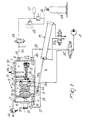
- figure 1 is a schematic view of a tilting casting chamber with some parts shown in cross-section; and
- figure 2 is a partially sectional schematic view of a firing and cooling apparatus which does not constitute the object of the present invention.
-
- Initially with reference to figure 1, said figure illustrates a casting apparatus which includes a
casting chamber 3 rotatably mounted about a horizontal axis, for example a pivot 14, so that thechamber 3 is rotatably supported. In order to tilt thechamber 3 about the axis of the pivot 14 there is, for example, a linear actuator which is constituted by a hydraulic or pneumatic cylinder-and-piston double-action unit 15 with astem 16 that is articulated to a lug 17. Theunit 15 is supplied by a suitable source of pressurized fluid by means of anelectropneumatic control valve 15a. - The space of the
chamber 3 is divided into two compartments A and B by anintermediate partition 19 with an opening 19a for connecting the compartments. - A
crucible 21 is provided in the compartment B and can be seated on abracket 20 at anelectrode 25 that generates an electric arc for melting ametal pellet 26 placed in thecrucible 21. - The compartment A contains a supporting
pan 27 provided withholes 28 for the passage of the inert gas and of the air to be aspirated. - The compartment A has a safety valve or
vent valve 60 of any suitable type which is arranged externally and meant to control the pressure of the inert gas so that it is kept equal to, or slightly higher than, atmospheric pressure throughout the casting, so as to avoid injecting inert gas in the molten metal and thus avoid forming bubbles and/or porosities. - With the above described apparatus, provided with a
vent valve 60, first of all thecasting cylinder 32 is loaded into the compartment A, moving the end of the casting cylinder that corresponds to the inlet of the casting so that it abuts against theannular gasket 36. Then atitanium pellet 26 is loaded into thecrucible 21. - The
pump 41 is then activated to produce a vacuum of approximately 4 millibar which is controlled by a Pirani-type probe. This operation continues for two or preferably three minutes, so as to ensure that the time is sufficient to degas the refractory 33. Then theduct 39 is closed by means of theelectric valve 42, while aspiration from the compartment A continues through theduct 37 and simultaneously low-pressure argon is fed into the compartment B to "pre-flush" the entire casting chamber. - The inert gas in fact passes from the compartment B through the opening 19a of the
partition 19 and, by virtue of thegasket 36, is forced to pass through all of theimpression 34 and exit through thevent channels 35 before it is aspirated into theduct 37 through theholes 28 of thepan 27. - At this point the
aspiration pump 41 is halted and a few seconds later theelectrode 25 is energized to produce the electric arc and cause melting, generally within 45 seconds. During the melting of the titanium, the inert gas continues to enter the compartment B at a flow-rate of approximately 4 liters/minute and therefore the compartments A and B saturate with argon (in approximately 30 seconds). - The
valve 15a is then energized, activating the double-action cylinder 15 which in turn tilts thecasting chamber 3 through 90° so as to cast the metal. - At this point the
check valve 48 is opened and injects into the compartment B, at a relatively modest pressure, inert gas that originates from theargon reserve 47; accordingly, a mild pressure-casting of the metal cast inside the impressions and the vent channels of thecylinder 32 occurs. However, most of the inert gas is discharged into the atmosphere by means of asafety valve 60 which thus keeps the pressure inside the casting chamber constant throughout the casting at a level that is equal to, or slightly higher than, approximately one atmosphere; this prevents the formation of defects and irregularities (bubbles, porosities) in the molten metal. - It is evident that the above described process allows to perform casting while the
casting cylinder 32 is cold, with a controlled ambient pressure and in an inert atmosphere, so as to eliminate the risk that said cylinder might react with oxygen to form oxides and with nitrogen to produce nitrides that could compromise the quality of the cast. The cast thus has almost-finished surfaces which only require a quick sanding. - The embodiment shown in figure 2, not covered by the appended claims, illustrates a firing and cooling apparatus which is formed by a
metal casing 61, made for example of stainless steel plate, with a cylindrical internal opening and with aside wall 62 and a closedbottom 63. The inside of the casing is lined with one or more layers of a suitableinsulating material 64 which can be configured so as to have an intermediate flange-like portion 65, which optionally includes anannular core 66 made of stainless steel that is welded to theside wall 62; said flange-like portion delimits a kiln chamber orcompartment 67 and a cooling compartment orchamber 68. - The
kiln chamber 67 is provided with suitable heating means, for example coil-shapedelectric resistors 69 which are electrically connected, by means of acable 70, to acontrol unit 71 which is in turn supplied by a suitable source of electric power. - The
cooling chamber 68 is instead surrounded by ametal coil 72 whose ends are connected to a circuit, generally designated by thereference numeral 73, for the forced circulation of a heat-transferring liquid, for example water or diathermic oil, which is passed through aheat sink 74 outside thechamber 68. - A
flange 75 is applied, for example welded, to the mouth of themetal casing 61 and internally delimits anopening 76 for access to thechambers action jacks casing 61; theirrespective stems casing 61. Thestems door 81 for closing the opening 76; said door has, on the face directed towards theflange 75, anannular sealing gasket 82 which is meant to abut against theflange 75. - The
door 81, by virtue of the action of thejacks flange 75. - The
door 81 furthermore supports, on the side directed towards the opening 76, one or more part holders, for example apan 83 on which it is possible to load adental prosthesis 84 formed by a cast-titanium support and by false teeth made of a ceramic material, which must be fired in the titanium support. More specifically, thepan 83 is fixed at the tip of astem 85 which is mounted so that it can slide through the door and can be actuated by a double-action jack 86 arranged on the other side of the door and rigidly coupled thereto. - The
jack 86 and thestem 85 can be advantageously arranged coaxially to the axis X-X. - The extension of the
stem 85 is such that once thedoor 81 has been moved into its closed position by thejacks pan 83, with itsload 84, can be moved into two separate positions, namely at the center of the kiln chamber 67 (maximum extension) and inside the cooling chamber. - One or both of the
chambers argon cylinder 87, by means of anelectric valve 88, and has adischarge hole 89 that is connected to aduct 90 which can be closed by anelectric valve 91 and directed to an aspiration system (pump) generally designated by thereference numeral 92. - The
chambers - The operation of the above described apparatus is very simple.
- Starting from a condition in which the
door 81 is fully open, as shown in the drawing, it is possible to easily access thepan 83 to load theprosthesis 84 on it. Then fluid is supplied to thejacks respective stems door 81 sealingly close the opening 76 by virtue of thegasket 82, which is pressed against theflange 75. - The
jack 86 is then energized and extends itsstem 85 so as to move thepan 83 and thepart 84 to the center of the upper firing region orkiln 67. At this point theaspiration system 92 is activated while theelectric valve 88 remains closed, until a vacuum of 4 millibar is produced; theelectric valve 88 is then opened to feed argon into thechambers - The
electric valve 88 is closed and power is fed to theelectric resistors 69 in order to obtain a firing temperature of for example 800°C inside thekiln 67. The time for which the prosthesis remains at the firing temperature of course depends on the type of ceramic material being used. - Once firing is complete, power is removed from the
resistors 69 and thejack 86 is activated, making its stem retract and thus lowering thepan 83, which moves into thequick cooling region 68 while remaining in an inert atmosphere at all times. - At this point the forced circulation of heat-transferring fluid (diathermic oil) through the
cooling system 73, and thus through thecoil 72, is activated. - In order to further accelerate the cooling process it is also possible to feed cold argon into the
chamber 68, for example by opening theelectric valve 88. - Cooling can be total or partial, i.e. below the oxidation temperature of titanium, which is approximately 250°C; once it has been achieved, the forced circulation of oil through the
system 73 is interrupted and thejacks door 81 into the open position, where theprosthesis 84 can be easily recovered and a new loading, firing and cooling cycle can begin. - The entire operating cycle of the apparatus can of course be controlled by a program by means of a suitable control unit.
- It is evident that the above described apparatus allows to drastically reduce the firing and cooling times in an inert and controlled atmosphere without requiring interventions or transfers or other manual movements of the part to be fired and then cooled.
- The apparatus of figure 2 is susceptible of numerous modifications and variations.
- Thus, for example, instead of the
jacks - The
door 81 may also be pivoted to the flange 75-or to thecasing 61; in this case it is possible to provide a single actuator for opening and closing it. - Furthermore, the
kiln section 67 and thecooling chamber section 68 can be separated by a movable insulating partition, for example of the shutter-like type, or of the moving-wall type that can be raised or lowered (by the movable unit formed by thepart 81, by thepan 83, and by other suitable devices) inside the kiln section, so as to close said kiln section during the cooling of thepart 84. - Where technical features mentioned in any claim are followed by reference signs, those reference signs have been included for the sole purpose of increasing the intelligibility of the claims and accordingly, such reference signs do not have any limiting effect on the scope of each element identified by way of example by such reference signs.
Claims (10)
- Firing and/or casting kiln which comprises:characterized in that said treatment chamber (3) is rotatably mounted about a horizontal axis (14) such that a pellet held by said part holder (21) arranged vertically is melted and then said treatment chamber is rotated about said horizontal axis (14) so that the melted pellet is poured by gravity into said casting cylinder (33).a containment casing which internally forms at least one treatment chamber (3);at least one part holder (21) which is movably mounted inside the, or the at least one, respective treatment chamber (3);a casting cylinder (33) arranged for receiving melted material from said part holder (21);at least one opening (19a) for access to the or each treatment chamber; andconditioning means (41,47) for producing a vacuum and introducing inert gas in the or each treatment chamber,
- Kiln according to claim 1, characterized in that said treatment chamber is a hermetically-closed casting chamber (3) which accommodates a crucible (21) and a casting cylinder (32) which are placed mutually adjacent within the casting chamber (3), said conditioning means comprising electric-arc heating means (25) for the load, means for aspirating air (41), at least one source (47) for delivering inert gas, and a discharge valve (60), said discharge valve being a safety valve meant to control the pressure of the inert gas in the casting chamber (3) during casting.
- Kiln according to claim 2, characterized in that said casting cylinder (32) contains refractory material (33) with an impression (34).
- Kiln according to any one or more of the preceding claims, characterized in that said conditioning means comprise means for aspirating air (41) both from the crucible section (B) and from the cylinder section (A).
- Kiln according to any one or more of the preceding claims, characterized in that said source (47) for delivering inert gas is connected to the treatment chamber (3) so as to supply gas to the crucible section (B).
- Kiln according to any one or more of the preceding claims 2-3 and 4-5 when dependent upon claims 2 and 3, characterized in that said discharge valve (60) is arranged downstream of the casting cylinder (32).
- Process for casting one or more loads of titanium in an inert atmosphere and under controlled pressure which comprises, in sequence:the preparation of a metal load to be cast in a crucible (21) located adjacent to a casting cylinder (32) with refractory and an impression, said crucible (21) and said cylinder (32) being arranged within a sealed casting chamber (3) that can be tilted and has electric-arc heating means (25) for said load, means for aspirating air (41) from the crucible section (B) and from the cylinder section (A), at least one source (47) for delivering inert gas to the crucible section (B), and a vent valve (60);the provision of a vacuum of at least 4 millibar within the casting chamber (3), said vacuum being controlled by a Pirani device by aspirating from the cylinder section (A) in order to adequately degas the refractory material (33) that delimits the casting impression (34);the supply of inert gas at a low pressure, on the order of approximately 0.2 bars, to "pre-flush" the casting chamber (3);the activation of electric-arc means (25) to melt the load;the interruption of the aspiration;the supply of inert gas until the casting chamber (3) is saturated;the tilting of the casting chamber (3) to cast from the crucible (21) into the casting cylinder (32);the supply of inert gas at a relatively high pressure to push the molten metal so that it enters the material inside the casting cylinder (32);the controlled external discharge of the inert gas at a threshold value that is equal to, or slightly higher than, the external atmospheric pressure, so as to have casting at constant and moderate pressure;and the removal of the casting cylinder (32) from the muffle.
- Process according to claim 7, characterized in that the initial vacuum before melting and casting occur is maintained for at least two minutes so as to produce high degassing of the casting cylinder (32).
- Process according to any one or more of claims 7 and 8, characterized in that the aspiration circuit is disconnected after the activation and triggering of the electric arc (25) to melt the load.
- Process according to any one or more of the preceding claims 7-9, characterized in that during the melting of the load or loads the inert gas is injected with a flow-rate of four liters per minute for approximately thirty seconds.
Applications Claiming Priority (4)
| Application Number | Priority Date | Filing Date | Title |
|---|---|---|---|
| ITVR930069 | 1993-09-20 | ||
| ITVR930069A IT1262803B (en) | 1993-09-20 | 1993-09-20 | Method and apparatus for melting in inert atmosphere and at controlled pressure for small batches of titanium and its alloys |
| ITVR930072 | 1993-09-28 | ||
| ITVR930072A IT1262804B (en) | 1993-09-28 | 1993-09-28 | Apparatus for baking and cooling, especially for ceramic material mounted on metal backing |
Publications (2)
| Publication Number | Publication Date |
|---|---|
| EP0651220A1 EP0651220A1 (en) | 1995-05-03 |
| EP0651220B1 true EP0651220B1 (en) | 1999-11-24 |
Family
ID=26332635
Family Applications (1)
| Application Number | Title | Priority Date | Filing Date |
|---|---|---|---|
| EP94114299A Expired - Lifetime EP0651220B1 (en) | 1993-09-20 | 1994-09-12 | Kiln for firing and/or casting prosthodontic products |
Country Status (4)
| Country | Link |
|---|---|
| US (2) | US5496017A (en) |
| EP (1) | EP0651220B1 (en) |
| DE (1) | DE4433373A1 (en) |
| ES (1) | ES2141791T3 (en) |
Families Citing this family (8)
| Publication number | Priority date | Publication date | Assignee | Title |
|---|---|---|---|---|
| US5685360A (en) * | 1996-03-14 | 1997-11-11 | Peacock Limited L.C. | Apparatus for the casting and autogenous welding of small metal loads in an inert atmosphere |
| US5954115A (en) * | 1997-02-06 | 1999-09-21 | Toymax Inc | Molding toy for molding toy metal objects |
| DE59802238D1 (en) * | 1997-04-03 | 2002-01-10 | Yasui Shouzui | METHOD AND CASTING DEVICE FOR Investment Casting |
| US6210628B1 (en) * | 1998-12-28 | 2001-04-03 | Howmet Research Corporation | Melt delivery system |
| US6902387B2 (en) * | 2001-12-07 | 2005-06-07 | Binney & Smith Inc. | Crayon maker |
| CN101893383B (en) * | 2010-07-23 | 2012-07-04 | 上海联川自动化科技有限公司 | Method and device for vacuumizing and filling inert gases in industrial furnace |
| FI124164B (en) * | 2011-05-27 | 2014-04-15 | Aalto Korkeakoulusäätiö | Arc melting and tipping molding device |
| ES2754701T3 (en) * | 2017-04-12 | 2020-04-20 | Ivoclar Vivadent Ag | Dental treatment device |
Family Cites Families (11)
| Publication number | Priority date | Publication date | Assignee | Title |
|---|---|---|---|---|
| US3336971A (en) * | 1964-12-16 | 1967-08-22 | Howe Sound Co | Vacuum melting and casting apparatus |
| US3510546A (en) * | 1967-12-15 | 1970-05-05 | Homogeneous Metals | Methods for powdering metals |
| US3952408A (en) * | 1970-03-26 | 1976-04-27 | Albert George Docx | Method of assembling a resistance furnace |
| US3747808A (en) * | 1971-11-12 | 1973-07-24 | Pennwalt Corp | Molten metal pouring device having pantograph tilting mechanism |
| EP0018450B1 (en) * | 1979-04-25 | 1983-06-22 | Iwatani Sangyo Kabushiki Kaisha | Metal casting apparatus |
| US4300037A (en) * | 1979-09-04 | 1981-11-10 | Oxy Dental Prod. Inc. | Electronic control system for a radiant furnace |
| DE3205729C2 (en) * | 1982-02-18 | 1985-02-21 | Dentsply International Inc., York, Pa. | Kilns, in particular vacuum kilns for dental ceramic purposes |
| EP0091742A3 (en) * | 1982-03-22 | 1984-07-11 | Austenal International Inc. | Dental pressure furnace |
| DE3405244C1 (en) * | 1984-02-15 | 1985-04-11 | Aichelin GmbH, 7015 Korntal-Münchingen | Industrial furnace, especially a multi-chamber vacuum furnace for the heat treatment of batches of metallic workpieces |
| US4865808A (en) * | 1987-03-30 | 1989-09-12 | Agency Of Industrial Science And Technology | Method for making hypereutetic Al-Si alloy composite materials |
| DE4302570C1 (en) * | 1993-01-29 | 1994-03-24 | Otto Kozmacs | Oven for firing dental ceramic material with titanium@ - has gastight walls, closure and material carrier and combustion chamber fed from beneath by conduit and connected at top to vacuum |
-
1994
- 1994-09-12 ES ES94114299T patent/ES2141791T3/en not_active Expired - Lifetime
- 1994-09-12 EP EP94114299A patent/EP0651220B1/en not_active Expired - Lifetime
- 1994-09-13 US US08/305,277 patent/US5496017A/en not_active Expired - Lifetime
- 1994-09-20 DE DE4433373A patent/DE4433373A1/en not_active Withdrawn
-
1995
- 1995-12-05 US US08/567,597 patent/US5634514A/en not_active Expired - Fee Related
Also Published As
| Publication number | Publication date |
|---|---|
| US5634514A (en) | 1997-06-03 |
| US5496017A (en) | 1996-03-05 |
| ES2141791T3 (en) | 2000-04-01 |
| EP0651220A1 (en) | 1995-05-03 |
| DE4433373A1 (en) | 1995-03-23 |
Similar Documents
| Publication | Publication Date | Title |
|---|---|---|
| RU2527535C2 (en) | Method and device for ingot isolation at initiation | |
| US5819837A (en) | Process and apparatus for melting and casting of metals in a mold | |
| EP0651220B1 (en) | Kiln for firing and/or casting prosthodontic products | |
| US8196641B2 (en) | Continuous casting sealing method | |
| RU2420368C2 (en) | Continuous casting of reactive metals in using glass coat | |
| KR20160018704A (en) | Hot isostatic pressing device | |
| EP0725151A1 (en) | Method and apparatus for refining molten metal | |
| EP0380637A1 (en) | High capacity electron beam cold hearth furnace. | |
| KR101425572B1 (en) | Furnace for melting Aluminum Puck by Precipitation | |
| JP3160842B2 (en) | Low pressure casting machine and low pressure casting method | |
| JP5091151B2 (en) | Infrared lamp heating casting apparatus and casting method | |
| GB2153722A (en) | Melting and pressure casting apparatus | |
| JPH0225701B2 (en) | ||
| JP2000271723A (en) | Holding furnace for casting metal | |
| KR100530326B1 (en) | Shroud nozzle top burner preheater | |
| EP0091742A2 (en) | Dental pressure furnace | |
| JPS609574A (en) | Casting device | |
| JPH05212062A (en) | Production of porcelain tooth and its apparatus | |
| RU2291758C2 (en) | Melting-pouring plant for producing small-size castings | |
| JPH0327860A (en) | Automatic pouring device | |
| JP2519835B2 (en) | Method and apparatus for hot isostatic pressing | |
| JPH0377762A (en) | Method for automatically supplying molten metal in die casting machine | |
| JPS63128111A (en) | Method for treating molten steel in remaining ladle | |
| JPH03103381A (en) | Metal impregnation treatment system | |
| JPH05237633A (en) | Casting method |
Legal Events
| Date | Code | Title | Description |
|---|---|---|---|
| PUAI | Public reference made under article 153(3) epc to a published international application that has entered the european phase |
Free format text: ORIGINAL CODE: 0009012 |
|
| AK | Designated contracting states |
Kind code of ref document: A1 Designated state(s): CH ES FR LI NL SE |
|
| 17P | Request for examination filed |
Effective date: 19951030 |
|
| 17Q | First examination report despatched |
Effective date: 19970404 |
|
| GRAG | Despatch of communication of intention to grant |
Free format text: ORIGINAL CODE: EPIDOS AGRA |
|
| GRAG | Despatch of communication of intention to grant |
Free format text: ORIGINAL CODE: EPIDOS AGRA |
|
| GRAH | Despatch of communication of intention to grant a patent |
Free format text: ORIGINAL CODE: EPIDOS IGRA |
|
| GRAH | Despatch of communication of intention to grant a patent |
Free format text: ORIGINAL CODE: EPIDOS IGRA |
|
| GRAA | (expected) grant |
Free format text: ORIGINAL CODE: 0009210 |
|
| AK | Designated contracting states |
Kind code of ref document: B1 Designated state(s): CH ES FR LI NL SE |
|
| PG25 | Lapsed in a contracting state [announced via postgrant information from national office to epo] |
Ref country code: SE Free format text: THE PATENT HAS BEEN ANNULLED BY A DECISION OF A NATIONAL AUTHORITY Effective date: 19991124 Ref country code: LI Free format text: LAPSE BECAUSE OF FAILURE TO SUBMIT A TRANSLATION OF THE DESCRIPTION OR TO PAY THE FEE WITHIN THE PRESCRIBED TIME-LIMIT Effective date: 19991124 Ref country code: CH Free format text: LAPSE BECAUSE OF FAILURE TO SUBMIT A TRANSLATION OF THE DESCRIPTION OR TO PAY THE FEE WITHIN THE PRESCRIBED TIME-LIMIT Effective date: 19991124 |
|
| REG | Reference to a national code |
Ref country code: CH Ref legal event code: EP |
|
| ET | Fr: translation filed | ||
| REG | Reference to a national code |
Ref country code: ES Ref legal event code: FG2A Ref document number: 2141791 Country of ref document: ES Kind code of ref document: T3 |
|
| REG | Reference to a national code |
Ref country code: CH Ref legal event code: PL |
|
| PLBE | No opposition filed within time limit |
Free format text: ORIGINAL CODE: 0009261 |
|
| STAA | Information on the status of an ep patent application or granted ep patent |
Free format text: STATUS: NO OPPOSITION FILED WITHIN TIME LIMIT |
|
| 26N | No opposition filed | ||
| PGFP | Annual fee paid to national office [announced via postgrant information from national office to epo] |
Ref country code: ES Payment date: 20070921 Year of fee payment: 14 |
|
| PGFP | Annual fee paid to national office [announced via postgrant information from national office to epo] |
Ref country code: NL Payment date: 20070928 Year of fee payment: 14 |
|
| PGFP | Annual fee paid to national office [announced via postgrant information from national office to epo] |
Ref country code: FR Payment date: 20070924 Year of fee payment: 14 |
|
| PG25 | Lapsed in a contracting state [announced via postgrant information from national office to epo] |
Ref country code: NL Free format text: LAPSE BECAUSE OF NON-PAYMENT OF DUE FEES Effective date: 20090401 |
|
| NLV4 | Nl: lapsed or anulled due to non-payment of the annual fee |
Effective date: 20090401 |
|
| REG | Reference to a national code |
Ref country code: FR Ref legal event code: ST Effective date: 20090529 |
|
| PG25 | Lapsed in a contracting state [announced via postgrant information from national office to epo] |
Ref country code: FR Free format text: LAPSE BECAUSE OF NON-PAYMENT OF DUE FEES Effective date: 20080930 |
|
| REG | Reference to a national code |
Ref country code: ES Ref legal event code: FD2A Effective date: 20080913 |
|
| PG25 | Lapsed in a contracting state [announced via postgrant information from national office to epo] |
Ref country code: ES Free format text: LAPSE BECAUSE OF NON-PAYMENT OF DUE FEES Effective date: 20080913 |