EP0650673A1 - Motorcyclist helmet including an aerodynamic stabilizer flap - Google Patents
Motorcyclist helmet including an aerodynamic stabilizer flap Download PDFInfo
- Publication number
- EP0650673A1 EP0650673A1 EP94830486A EP94830486A EP0650673A1 EP 0650673 A1 EP0650673 A1 EP 0650673A1 EP 94830486 A EP94830486 A EP 94830486A EP 94830486 A EP94830486 A EP 94830486A EP 0650673 A1 EP0650673 A1 EP 0650673A1
- Authority
- EP
- European Patent Office
- Prior art keywords
- helmet
- flap
- stabilizer flap
- stabilizer
- helmet according
- Prior art date
- Legal status (The legal status is an assumption and is not a legal conclusion. Google has not performed a legal analysis and makes no representation as to the accuracy of the status listed.)
- Withdrawn
Links
- 239000003381 stabilizer Substances 0.000 title claims abstract description 30
- 230000000087 stabilizing effect Effects 0.000 claims description 9
- 230000000452 restraining effect Effects 0.000 claims description 3
- 238000005273 aeration Methods 0.000 claims 1
- 238000010276 construction Methods 0.000 description 5
- 230000000694 effects Effects 0.000 description 5
- 230000006870 function Effects 0.000 description 4
- 238000000034 method Methods 0.000 description 4
- 239000000463 material Substances 0.000 description 3
- 230000005484 gravity Effects 0.000 description 2
- UJCHIZDEQZMODR-BYPYZUCNSA-N (2r)-2-acetamido-3-sulfanylpropanamide Chemical compound CC(=O)N[C@@H](CS)C(N)=O UJCHIZDEQZMODR-BYPYZUCNSA-N 0.000 description 1
- 241001669680 Dormitator maculatus Species 0.000 description 1
- 238000006073 displacement reaction Methods 0.000 description 1
- 239000000428 dust Substances 0.000 description 1
- 239000012530 fluid Substances 0.000 description 1
- 239000003292 glue Substances 0.000 description 1
- 230000009993 protective function Effects 0.000 description 1
Images



Classifications
-
- A—HUMAN NECESSITIES
- A42—HEADWEAR
- A42B—HATS; HEAD COVERINGS
- A42B3/00—Helmets; Helmet covers ; Other protective head coverings
- A42B3/04—Parts, details or accessories of helmets
- A42B3/0493—Aerodynamic helmets; Air guiding means therefor
-
- A—HUMAN NECESSITIES
- A42—HEADWEAR
- A42B—HATS; HEAD COVERINGS
- A42B3/00—Helmets; Helmet covers ; Other protective head coverings
- A42B3/04—Parts, details or accessories of helmets
- A42B3/28—Ventilating arrangements
- A42B3/281—Air ducting systems
- A42B3/283—Air inlets or outlets, with or without closure shutters
Definitions
- the present invention relates to a helmet for motorcyclists, motorists and cyclists, which has been specifically designed for providing, during the running, good aerodynamic stabilizing properties.
- crash helmets for protecting the user from damages, in the case of a fall, and moreover from wind, dust and rain.
- the aim of the present invention is to overcome the above mentioned drawbacks, by providing a crash helmet which, in addition to a protective function thereof, is also adapted to neutralize the above mentioned negative effects, which helmet, in particular, can be safely and comfortably used at high speeds.
- a main object of the present invention is to provide a helmet for the mentioned applications, which is specifically adapted to neutralize the loads and aerodynamic turbulences negatively affecting the longitudinal and cross axes of the helmet, and this by exploiting the well known Venturi effect.
- Another object of the present invention is to provide a helmet construction including a stabilizer flap element adapted to cause the air passing between said stabilizer flap element and the helmet cap to be compressed and accelerated without improving and stabilizing the running performance.
- Another object of the present invention is to provide such a helmet construction which is specifically designed to reduce the aerodynamic load on the neck of a driver, and this owing to the capability of the mentioned stabilizer flap element to be backwardly or frontwardly displaced.
- Another object of the present invention is to provide such a helmet construction which has a smaller weight, and is more stable and noiseless than a conventional type of helmet.
- Yet another object of the present invention is to provide such a helmet construction adapted to greatly reduce the pressure exerted by the air on the driver neck.
- Figure 1 illustrates the assembled portions forming the stabilizer device associated with the subject helmet, that is: a central guide A to be affixed to the top of the helmet cap along the longitudinal axis thereof, and to operate for guiding the support element supporting the flap element C;
- Figure 1A illustrates the subject helmet with the stabilizer device shown by three views, that is a side, a front and a top plan view.
- portion A operating as a guide encompasses, in its central portion, the helmet for about 3/4 of its longitudinal surface starting from the visor of the helmet. This has been specifically provided to allow a very great displacement along the axis thereof of the support element B with the flap C.
- the flap element follows the curved profile of the helmet cap, with the same radius up to near the middle line of the visor.
- the curved configuration of the stabilizer flap can change its radius up to assume a rectilinear configuration depending on the aerodynamic requirements to allow less or more air to pass between said flap and helmet cap.
- the helmet is shown by an exploded view of the main elements thereof, that is: the stabilizer flap C, the supporting element B and guide A.
- the guide A which can be made of different material to provide it with a set flexibility or resiliency and to fit several commercially available helmets, is hollow in its inside in order to reduce its weight and allow air to enter said guide or exit said guide through suitable ducts and holes on the cap inside the helmet with an inner aerating function of the helmet and, as shown in Figure 1D, being fully open.
- a first baffle element at the rear end portion of the helmet allow air to better flow and moreover it provides a stop abutment for the guide A.
- the supporting element B can be made of several materials, and be connected to the flap by several elements such as glue, screws or the like, or they can also be made in a single piece. Said supporting element, in particular, is fixedly connected to the guide A in order to allow it to slide backwardly and frontwardly for adjustment purposes and being being adapted to be locked at a desired or set position.
- Figures 2B and 3B are cross sectional views illustrating some connecting means, of the dovetail type E, of a rail type F, of a slider type G and of a spritting type E.
- Figure 1C illustrates the passage of the fluid air threads between the helmet cap and stabilizer flap, as shown cross section.
- the cross section of said stabilizer flap has a suitable NACA wing profile in order to improve the aerodynamic efficiency.
- the shape, size and thickness thereof can be selected as required.
- Figure 2C illustrates the stabilizer flap C affixed to the supporting element B by means of the screw X.
- Said screw is adapted, in addition to affixing the stabilizer flap to the supporting element B, to lock said stabilizer flap by projecting from the bottom thereof onto the guide A.
- the screw Z is provided for raising or lowering the rear portion of the stabilizer flap, and accordingly to change his attitude, and this by screwing on or off said screw Z.
- the supporting element B is hollow in its central portion in order to allow the guide A to change the longitudinal radius thereof, so as to be fitted to different size of helmet cap; said aperture, in addition to improve the resiliency characteristics, will also eliminate the friction due to difference of the two radii which would occur at the central and peripheric portion.
- Figures 1D, 2D, 3D show the aerodynamic effect of the stabilizer flap in several attitudes assumed by the helmet depending on the running speed.
- the stabilizer flap is arranged at the helmet center of gravity, and, accordingly, the stabilizing function thereof is distributed on the vertical line thereof, and the resultant of the operating forces is nearly zero, mainly in a low speed condition.
Landscapes
- Physics & Mathematics (AREA)
- Fluid Mechanics (AREA)
- Helmets And Other Head Coverings (AREA)
Abstract
A crash helmet for motorcyclists, motorists, and cyclists, comprises a device, including one or more elements, having a half round configuration, both in the longitudinal and in the cross direction of the spheric body of the helmet, the device being constituted by three mutually coupled elements, comprising a guide element (A), a stabilizer flap supporting element (B), and a stabilizer flap (C), these elements being mutually connected either in a movable manner, or in a fixed and monolithic manner.
Description
- The present invention relates to a helmet for motorcyclists, motorists and cyclists, which has been specifically designed for providing, during the running, good aerodynamic stabilizing properties.
- As is known, in the motorcycle field, but also in the bicycle and motor vehicle field in general, there are used crash helmets for protecting the user from damages, in the case of a fall, and moreover from wind, dust and rain.
- In particular, in the case of a motorcycle crash helmet, the very high running speeds of modern motorcycles originate great problems for a motorcycle driver, in particular at his/her head and neck, because of the drag and turbulence of the air being displaced, which involves a very high physical stress on the driver. Usually, such a stress causes the driver to be fatigued, with a consequent reduction of his driving capabilities, and with dangerous consequences for the driver himself.
- Those same problems also occur in the case of helmets used in bicycle and motor vehicle sports.
- Accordingly, the aim of the present invention is to overcome the above mentioned drawbacks, by providing a crash helmet which, in addition to a protective function thereof, is also adapted to neutralize the above mentioned negative effects, which helmet, in particular, can be safely and confortably used at high speeds.
- Within the scope of the above mentioned aim, a main object of the present invention is to provide a helmet for the mentioned applications, which is specifically adapted to neutralize the loads and aerodynamic turbulences negatively affecting the longitudinal and cross axes of the helmet, and this by exploiting the well known Venturi effect.
- Another object of the present invention is to provide a helmet construction including a stabilizer flap element adapted to cause the air passing between said stabilizer flap element and the helmet cap to be compressed and accelerated without improving and stabilizing the running performance.
- Another object of the present invention is to provide such a helmet construction which is specifically designed to reduce the aerodynamic load on the neck of a driver, and this owing to the capability of the mentioned stabilizer flap element to be backwardly or frontwardly displaced.
- Another object of the present invention is to provide such a helmet construction which has a smaller weight, and is more stable and noiseless than a conventional type of helmet.
- Yet another object of the present invention is to provide such a helmet construction adapted to greatly reduce the pressure exerted by the air on the driver neck.
- According to one aspect of the present invention, the above mentioned aim and objects, as well as yet other objects, which will become more apparent hereinafter, are achieved by a helmet construction having the features of the characterizing part of the main Claim.
- Further features of the helmet according to the invention are stated in the depending claims.
- The above and other functional and constructional characteristics of the helmet according to the present invention will become more apparent hereinafter from the following detailed disclosure of a preferred embodiment thereof, which is illustrated, by way of an indicative, but not limitative example, in the accompanying drawings, where:
- Figure 1 illustrates the assembled portions forming the stabilizer device associated with the subject helmet, that is:
a central guide A to be affixed to the top of the helmet cap along the longitudinal axis thereof, and to operate for guiding the support element supporting the flap element C; - Figure 1A illustrates the subject helmet with the stabilizer device shown by three views, that is a side, a front and a top plan view.
- In this figures it should be apparent that the portion A operating as a guide encompasses, in its central portion, the helmet for about 3/4 of its longitudinal surface starting from the visor of the helmet. This has been specifically provided to allow a very great displacement along the axis thereof of the support element B with the flap C.
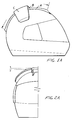
- In Figure 2A the flap element follows the curved profile of the helmet cap, with the same radius up to near the middle line of the visor.
- In particular, the curved configuration of the stabilizer flap can change its radius up to assume a rectilinear configuration depending on the aerodynamic requirements to allow less or more air to pass between said flap and helmet cap.
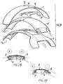
- In Figure 1B, the helmet is shown by an exploded view of the main elements thereof, that is:
the stabilizer flap C, the supporting element B and guide A. - The guide A, which can be made of different material to provide it with a set flexibility or resiliency and to fit several commercially available helmets, is hollow in its inside in order to reduce its weight and allow air to enter said guide or exit said guide through suitable ducts and holes on the cap inside the helmet with an inner aerating function of the helmet and, as shown in Figure 1D, being fully open.
- A first baffle element at the rear end portion of the helmet allow air to better flow and moreover it provides a stop abutment for the guide A.
- In this connection it should be pointed out that the size and the height of said guide, which can be made rigid with the helmet cap by suitable restraining means, will depend on the international standardizing rules in this field.
- The supporting element B can be made of several materials, and be connected to the flap by several elements such as glue, screws or the like, or they can also be made in a single piece. Said supporting element, in particular, is fixedly connected to the guide A in order to allow it to slide backwardly and frontwardly for adjustment purposes and being being adapted to be locked at a desired or set position.
- Figures 2B and 3B are cross sectional views illustrating some connecting means, of the dovetail type E, of a rail type F, of a slider type G and of a spritting type E.
- Figure 1C illustrates the passage of the fluid air threads between the helmet cap and stabilizer flap, as shown cross section.
- In particular, the cross section of said stabilizer flap has a suitable NACA wing profile in order to improve the aerodynamic efficiency.
- Moreover, the shape, size and thickness thereof can be selected as required.
- Figure 2C illustrates the stabilizer flap C affixed to the supporting element B by means of the screw X.
- Said screw is adapted, in addition to affixing the stabilizer flap to the supporting element B, to lock said stabilizer flap by projecting from the bottom thereof onto the guide A.
- The screw Z is provided for raising or lowering the rear portion of the stabilizer flap, and accordingly to change his attitude, and this by screwing on or off said screw Z.
- The supporting element B is hollow in its central portion in order to allow the guide A to change the longitudinal radius thereof, so as to be fitted to different size of helmet cap; said aperture, in addition to improve the resiliency characteristics, will also eliminate the friction due to difference of the two radii which would occur at the central and peripheric portion.
- It is also used for reducing the engagement force thereof on the guide C since, for safety reasons, in the case of a fall of the motorcyclist, it must be detached together with the stabilizer flap in order to prevent possible occurring frictions from damaging the head and neck of the driver.
- It is also possible to split the three elements A, B, C and affix them to the helmet in any suitable manner.
- Figures 1D, 2D, 3D show the aerodynamic effect of the stabilizer flap in several attitudes assumed by the helmet depending on the running speed.
- In Figure 1D, the stabilizer flap is arranged at the helmet center of gravity, and, accordingly, the stabilizing function thereof is distributed on the vertical line thereof, and the resultant of the operating forces is nearly zero, mainly in a low speed condition.
- Figure 2D, related to a middle speed condition, the helmet is slanted or tilted, whereas the stabilizer flap will be backwardly displaced so as to cause the resultant of its stabilizing action to fall on the center or of gravity. It should be apparent therein the greater effect provided by the flap for compensating the aerodynamic unbalance and, as the speed increases, the stabilizing function thereof will correspondingly increase as shown in Figure 3D.
- At a very high speed, for which the function of the stabilizer flap in a standard position is not sufficient, that is with the stabilizer flap parallel to the helmet cap surface, it is possible to change (Figure 2C) its position in order to obtain the desired aerodynamic compensating effect.
- It should be apparent that the drawings and disclosure have been provided exclusively by way of an indicative but not limitative example, and exclusively in order to disclose the main features of the inventive helmet.
- It should be also apparent that the method for making the helmet and the procedure use thereof, as well as the used materials can be varied within the scope of the invention.
- In particular, the mentioned variations can be directed to the above disclosed operating parts, features of the present invention, as well as to the making method thereof, the assembling method thereof, and this without departing from the scope of the invention.
Claims (11)
- A crash helmet for motorcyclists, motorists and cyclists, characterized in that said helmet is provided with an aerodynamic stabilizing device, said device comprising one or more elements, having a half-round configuration, both in the longitudinal and in the cross direction of the helmet spheric body.
- A helmet according to Claim 1, characterized in that said stabilizing device comprises three mutually coupled elements, said elements including a guide element, a stabilizer flap supporting element and a stabilizer flap element.
- A helmet according to Claim 2, characterized in that said three elements are movably coupled to one another.
- A helmet according to Claim 2, characterized in that said three elements are mutually coupled in a fixed and monolithic manner.
- A helmet according to any preceding claims, characterized in that said aerodynamic stabilizing device is removably affixed on the helmet top central portion, so as to be disengaged under an outer impact stress.
- A helmet according to any preceding claims, characterized in that said stabilizer flap is provided with a cross section having a wing profile and extending in parallel to the helmet cap.
- A helmet according to any preceding claims, characterized in that said stabilizer flap is affixed to the helmet so as to change the attitude of said stabilizer flap with respect to the helmet cap.
- A helmet according to any preceding claims, characterized in that said stabilizer flap supporting element, which supports at the top portion thereof said stabilizer flap, is adapted to slide backwardly and frontwardly in said guide element, detent means being provided for restraining the sliding movement of said supporting element.
- A helmet according to any preceding claims, characterized in that said guide element affixed to the cap of said helmet and guiding said supporting element comprises a restraining section adapted to allow said supporting element to slide along said guide without disengaging therefrom, said guide element operating as an inlet and outlet air guiding element for providing aeration air to the inside of said helmet.
- A helmet according to any preceding claims, characterized in that said aerodynamic device is adapted to press and stabilize the air passing between said stabilizer flap and said helmet cap so as to improve said air flow thereby providing a reduced pressure on a driver neck.
- A helmet according to any preceding claims, characterized in that said aerodynamic stabilizing device is adapted to also neutralize the loads and aerodynamic turbulences affecting the longitudinal and cross axis of said helmet.
Applications Claiming Priority (2)
| Application Number | Priority Date | Filing Date | Title |
|---|---|---|---|
| ITMI930786U | 1993-10-13 | ||
| ITMI930786 IT230468Y1 (en) | 1993-10-13 | 1993-10-13 | HELMET FOR MOTORCYCLISTS EQUIPPED WITH ADJUSTABLE REAR AERODYNAMIC STABILIZER |
Publications (1)
| Publication Number | Publication Date |
|---|---|
| EP0650673A1 true EP0650673A1 (en) | 1995-05-03 |
Family
ID=11365833
Family Applications (1)
| Application Number | Title | Priority Date | Filing Date |
|---|---|---|---|
| EP94830486A Withdrawn EP0650673A1 (en) | 1993-10-13 | 1994-10-13 | Motorcyclist helmet including an aerodynamic stabilizer flap |
Country Status (2)
| Country | Link |
|---|---|
| EP (1) | EP0650673A1 (en) |
| IT (1) | IT230468Y1 (en) |
Cited By (12)
| Publication number | Priority date | Publication date | Assignee | Title |
|---|---|---|---|---|
| USD457274S1 (en) | 2001-04-26 | 2002-05-14 | Shoei Co., Ltd. | Helmet |
| USD457691S1 (en) | 2001-04-26 | 2002-05-21 | Shoei Co., Ltd. | Helmet |
| USD458415S1 (en) | 2001-04-26 | 2002-06-04 | Shoei Co., Ltd. | Helmet |
| USD460219S1 (en) | 2001-04-26 | 2002-07-09 | Shoei Co., Ltd. | Helmet |
| EP2044854A3 (en) * | 2007-10-04 | 2009-11-04 | Arai Helmet Ltd | Helmet |
| EP2027787A4 (en) * | 2006-06-13 | 2010-12-01 | Ogk Kabuto Co Ltd | WAKE STABILIZER FOR A HELMET AND HELMET |
| EP2873337A3 (en) * | 2013-11-19 | 2015-10-28 | Arai Helmet Ltd | Helmet |
| US9398782B2 (en) | 2010-04-23 | 2016-07-26 | Felt Racing, Llc | Aerodynamic bicycle helmet |
| DE102015216436A1 (en) | 2015-08-27 | 2017-03-02 | Bayerische Motoren Werke Aktiengesellschaft | Hard hat with aerodynamic stabilization element |
| US9955125B2 (en) | 2008-10-23 | 2018-04-24 | Felt Racing, Llc | Bicycle handlebar video system |
| EP3466286A1 (en) * | 2017-10-05 | 2019-04-10 | Lionel Marsanne | Ventilating shell and garment or rucksack having at least one such shell |
| JP2024520737A (en) * | 2021-06-02 | 2024-05-24 | 建軍 米 | Helmets and how to use them |
Citations (7)
| Publication number | Priority date | Publication date | Assignee | Title |
|---|---|---|---|---|
| US3496854A (en) * | 1968-03-05 | 1970-02-24 | Ilc Ind Inc | Ventilated helmet |
| DE3305735A1 (en) * | 1983-02-18 | 1984-08-30 | Bayerische Motoren Werke AG, 8000 München | Protective helmet for motorcyclists or the like |
| WO1987003457A1 (en) * | 1984-12-05 | 1987-06-18 | Foehl Artur | Protective helmet for motor-cyclists, racing drivers and similar |
| EP0320622A2 (en) * | 1987-12-15 | 1989-06-21 | NOLAN S.p.A. | Safety helmet for motor-cyclists provided with manually-adjustable ventilation means |
| DE3822252A1 (en) * | 1988-07-01 | 1990-01-25 | Bayerische Motoren Werke Ag | Protective helmet |
| US5165116A (en) * | 1990-09-10 | 1992-11-24 | Simpson Elwood J B | Anti buffeting safety-racing helmet |
| WO1993004603A1 (en) * | 1991-09-12 | 1993-03-18 | Protector Development | Helmet with air and sound ducts |
-
1993
- 1993-10-13 IT ITMI930786 patent/IT230468Y1/en active IP Right Grant
-
1994
- 1994-10-13 EP EP94830486A patent/EP0650673A1/en not_active Withdrawn
Patent Citations (7)
| Publication number | Priority date | Publication date | Assignee | Title |
|---|---|---|---|---|
| US3496854A (en) * | 1968-03-05 | 1970-02-24 | Ilc Ind Inc | Ventilated helmet |
| DE3305735A1 (en) * | 1983-02-18 | 1984-08-30 | Bayerische Motoren Werke AG, 8000 München | Protective helmet for motorcyclists or the like |
| WO1987003457A1 (en) * | 1984-12-05 | 1987-06-18 | Foehl Artur | Protective helmet for motor-cyclists, racing drivers and similar |
| EP0320622A2 (en) * | 1987-12-15 | 1989-06-21 | NOLAN S.p.A. | Safety helmet for motor-cyclists provided with manually-adjustable ventilation means |
| DE3822252A1 (en) * | 1988-07-01 | 1990-01-25 | Bayerische Motoren Werke Ag | Protective helmet |
| US5165116A (en) * | 1990-09-10 | 1992-11-24 | Simpson Elwood J B | Anti buffeting safety-racing helmet |
| WO1993004603A1 (en) * | 1991-09-12 | 1993-03-18 | Protector Development | Helmet with air and sound ducts |
Cited By (19)
| Publication number | Priority date | Publication date | Assignee | Title |
|---|---|---|---|---|
| USD457691S1 (en) | 2001-04-26 | 2002-05-21 | Shoei Co., Ltd. | Helmet |
| USD458415S1 (en) | 2001-04-26 | 2002-06-04 | Shoei Co., Ltd. | Helmet |
| USD460219S1 (en) | 2001-04-26 | 2002-07-09 | Shoei Co., Ltd. | Helmet |
| USD457274S1 (en) | 2001-04-26 | 2002-05-14 | Shoei Co., Ltd. | Helmet |
| US8726425B2 (en) | 2006-06-13 | 2014-05-20 | Ogk Kabuto Co., Ltd. | Wake stabilizer for helmet and helmet |
| EP2027787A4 (en) * | 2006-06-13 | 2010-12-01 | Ogk Kabuto Co Ltd | WAKE STABILIZER FOR A HELMET AND HELMET |
| EP2044854A3 (en) * | 2007-10-04 | 2009-11-04 | Arai Helmet Ltd | Helmet |
| TWI402043B (en) * | 2007-10-04 | 2013-07-21 | Arai Helmet Ltd | Helmet |
| CN101401668B (en) * | 2007-10-04 | 2011-06-08 | 株式会社新井安全帽 | Helmet |
| US9955125B2 (en) | 2008-10-23 | 2018-04-24 | Felt Racing, Llc | Bicycle handlebar video system |
| US9398782B2 (en) | 2010-04-23 | 2016-07-26 | Felt Racing, Llc | Aerodynamic bicycle helmet |
| EP2873337A3 (en) * | 2013-11-19 | 2015-10-28 | Arai Helmet Ltd | Helmet |
| US9370217B2 (en) | 2013-11-19 | 2016-06-21 | Michio Arai | Helmet |
| DE102015216436A1 (en) | 2015-08-27 | 2017-03-02 | Bayerische Motoren Werke Aktiengesellschaft | Hard hat with aerodynamic stabilization element |
| WO2017032577A1 (en) * | 2015-08-27 | 2017-03-02 | Bayerische Motoren Werke Aktiengesellschaft | Safety helmet with an aerodynamic stabilizing element |
| US11166509B2 (en) | 2015-08-27 | 2021-11-09 | Bayerische Motoren Werke Aktiengesellschaft | Safety helmet with an aerodynamic stabilizing element |
| EP3466286A1 (en) * | 2017-10-05 | 2019-04-10 | Lionel Marsanne | Ventilating shell and garment or rucksack having at least one such shell |
| FR3072005A1 (en) * | 2017-10-05 | 2019-04-12 | Lionel Marsanne | AERATION SHELL AND GARMENT OR BACKPACK HAVING AT LEAST ONE SUCH SHELL |
| JP2024520737A (en) * | 2021-06-02 | 2024-05-24 | 建軍 米 | Helmets and how to use them |
Also Published As
| Publication number | Publication date |
|---|---|
| ITMI930786U1 (en) | 1995-04-13 |
| ITMI930786V0 (en) | 1993-10-13 |
| IT230468Y1 (en) | 1999-06-07 |
Similar Documents
| Publication | Publication Date | Title |
|---|---|---|
| US4911494A (en) | Cowling assembly for motorcycles | |
| US5261124A (en) | Eye shield assembly for cap visor | |
| US5678884A (en) | Air guide device with air intake openings | |
| US3927421A (en) | Helmet visor | |
| IT1223434B (en) | PROTECTIVE HELMET FOR MOTORCYCLISTS AND SIMILAR EQUIPPED WITH VENTILATION VEHICLES, MANUALLY ADJUSTABLE | |
| US5097538A (en) | Helmet | |
| EP3138429B1 (en) | Aerodynamic control device and helmet including the same | |
| CA2056289A1 (en) | Shroud-fin integration shelf for a helicopter empennage structure | |
| US4354285A (en) | Face shield and helmet | |
| US20140338106A1 (en) | Helmet with removable chin guard | |
| US20220322778A1 (en) | Adjustable spoiler for Motorcycle helmet | |
| US6278408B1 (en) | Vehicle antenna display system | |
| EP1495954A2 (en) | Windshield device for a straddle type vehicle | |
| EP2027787B1 (en) | Wake stabilizer for helmet and helmet | |
| US5267767A (en) | Bicycle fairing | |
| US5271102A (en) | Helmet with fluid flow termination surface | |
| JPS6119469B2 (en) | ||
| US9387899B1 (en) | Adjustable open-air vehicle windshield implement for forced air displacement | |
| CN215270836U (en) | Helmet | |
| US12550962B2 (en) | Protective helmet with an optimized aerodynamic deflector | |
| US20250276754A1 (en) | Leaning Vehicle | |
| US5853216A (en) | Air shield | |
| CN215685150U (en) | Helmet with simple braid mounting structure | |
| JPS6324083B2 (en) | ||
| EP3243399A1 (en) | A cycle helmet and a cycle helmet system |
Legal Events
| Date | Code | Title | Description |
|---|---|---|---|
| PUAI | Public reference made under article 153(3) epc to a published international application that has entered the european phase |
Free format text: ORIGINAL CODE: 0009012 |
|
| AK | Designated contracting states |
Kind code of ref document: A1 Designated state(s): BE CH DE ES FR GB LI NL SE |
|
| STAA | Information on the status of an ep patent application or granted ep patent |
Free format text: STATUS: THE APPLICATION IS DEEMED TO BE WITHDRAWN |
|
| 18D | Application deemed to be withdrawn |
Effective date: 19951104 |