EP0650617B1 - Modem for communicating with enclosed electronic equipment - Google Patents
Modem for communicating with enclosed electronic equipment Download PDFInfo
- Publication number
- EP0650617B1 EP0650617B1 EP93915608A EP93915608A EP0650617B1 EP 0650617 B1 EP0650617 B1 EP 0650617B1 EP 93915608 A EP93915608 A EP 93915608A EP 93915608 A EP93915608 A EP 93915608A EP 0650617 B1 EP0650617 B1 EP 0650617B1
- Authority
- EP
- European Patent Office
- Prior art keywords
- modem
- radiation
- interface
- complementary
- serial
- Prior art date
- Legal status (The legal status is an assumption and is not a legal conclusion. Google has not performed a legal analysis and makes no representation as to the accuracy of the status listed.)
- Expired - Lifetime
Links
Images


Classifications
-
- H—ELECTRICITY
- H04—ELECTRIC COMMUNICATION TECHNIQUE
- H04B—TRANSMISSION
- H04B10/00—Transmission systems employing electromagnetic waves other than radio-waves, e.g. infrared, visible or ultraviolet light, or employing corpuscular radiation, e.g. quantum communication
- H04B10/80—Optical aspects relating to the use of optical transmission for specific applications, not provided for in groups H04B10/03 - H04B10/70, e.g. optical power feeding or optical transmission through water
- H04B10/801—Optical aspects relating to the use of optical transmission for specific applications, not provided for in groups H04B10/03 - H04B10/70, e.g. optical power feeding or optical transmission through water using optical interconnects, e.g. light coupled isolators, circuit board interconnections
-
- G—PHYSICS
- G06—COMPUTING OR CALCULATING; COUNTING
- G06F—ELECTRIC DIGITAL DATA PROCESSING
- G06F13/00—Interconnection of, or transfer of information or other signals between, memories, input/output devices or central processing units
- G06F13/38—Information transfer, e.g. on bus
- G06F13/40—Bus structure
-
- G—PHYSICS
- G06—COMPUTING OR CALCULATING; COUNTING
- G06F—ELECTRIC DIGITAL DATA PROCESSING
- G06F13/00—Interconnection of, or transfer of information or other signals between, memories, input/output devices or central processing units
- G06F13/38—Information transfer, e.g. on bus
- G06F13/40—Bus structure
- G06F13/4063—Device-to-bus coupling
Definitions
- This invention relates to a portable interface unit or modem which permits temporary bidirectional communication between enclosed electronic process control equipment and a general purpose personal computer, without electrical connection between the two.
- Radiation transducers are frequently used to provide a communications link between two or more devices in conditions where the devices are required to be electrically isolated or where a standard electrical connection would be unsuitable.
- Radiation transducers can function as a communications link between two devices in the following ways: unidirectionally, also known as simplex communication; and bidirectionally in both directions, known as duplex communication.
- dumb keypad In the Woodward patent, simplex communication takes place between the dumb keypad and the process control equipment when the keypad is docked in a recess in the case of the process control equipment.
- the dumb keypad allows the operator to control and change various parameters of the monitoring device.
- the monitoring device on the other hand, is incapable of communicating with the keypad.
- the keypad is used to retrieve data from the memory of the monitoring unit by means of the display. This technique of retrieving data may be impractical in certain circumstances, particularly when a significant amount of data has been stored by the unit over an extended period of time. Furthermore, it may be impractical, except in the simplest of cases, to use the dumb keypad to program or reprogram the monitoring unit, especially when a plurality of monitoring units must be identically programmed or reprogrammed.
- Communications links such as electromagnetic, ultrasonic and infrared links, are increasingly being used in a number of applications for monitoring and reprogramming electronically controlled equipment in sealed or tamperproof enclosures.
- the physical structure of the actual radiation link may take many forms, but in general each type of equipment, or even the same type of equipment from different manufactures, forming one end of such a link requires a customized monitoring and/or programming unit providing the other portion of the link.
- Such specialized units are expensive, and may not provide for functions such as diagnosis and repair of malfunctioning units, or field testing of units under development. Depending on the application, it may also be necessary to protect the unit against adverse environments, and to ensure that it is intrinsically safe for use in hazardous environments.
- Such a unit is the Series 847 Portable ENRAF Terminal (PET) available from Enraf-Nonius and adapted to interface through an optical fibre link with gauges manufactured by that company.
- PET Portable ENRAF Terminal
- Such a weatherproof and intrinsically safe product is necessarily expensive to produce, yet is useful only for its own limited purposes.
- a field engineer on the other hand may need to deal with many types of equipment, and may need facilities beyond those provided by a specialized terminal of this nature.
- modems which convert the serial data to and from a form suitable for communication over the type of data link to be utilized, and provide an interface to and from that data link.
- the present invention provides a modem which permits a personal computer to access data stored in enclosed electronic equipment without electrical connection to the equipment, and to download the data to the computer.
- the invention also permits the computer to access the internal programming of the enclosed electronic equipment and to program or reprogram the equipment, or transfer data to it, assuming that the equipment has provision for duplex communication by radiation of energy through its casing.
- a process control unit, or electronic equipment in general be protected against tampering by unauthorized users.
- Electronic equipment possessing conventional external data transfer facilities are subject to tampering.
- the modem of the present invention creates a temporary communications link between the interface unit and enclosed electronic equipment which does not require an electrical connection. Therefore, the electronic equipment is not required to possess conventional external data transfer facilities and is, accordingly, tamper resistant.
- the present invention also provides for a non-electrical coupling between the enclosed electronic equipment and the modem in which there is no potential risk of creating an electric spark or spark discharge.
- This spark free connection is particularly suitable for applications in highly flammable and explosive environments.
- the modem enables bidirectional communication between a personal computer and enclosed electronic equipment.
- a standardized serial interface is used to connect the interface unit to the computer.
- Radiation transceivers are used to establish the portion of the communications link between the interface unit and the enclosed electronic equipment.
- the present invention in another aspect, is directed to a portable interface unit having a part which may be docked and releasably retained on enclosed electronic equipment having suitable docking means.
- an interface unit or modem capable of providing bidirectional communication and having, on the one hand a radiation interface for use in a radiation coupling relationship with a radiation interface of a sealed or tamperproof electronic unit, and, on the other hand an industry standard serial digital interface.
- This enables a general purpose personal computer, such as a lap-top or other portable computer, equipped with suitable programs and data storage capacity, to be linked conveniently to environmentally sealed or tamperproofed electronic equipment to be monitored via an optical interface.
- the unit may be battery powered, or, alternatively, may draw power from the host computer if sufficient power to operate the radiation link is within the specifications of the interface, which will usually be nominally in accordance with the requirements of the current version of the RS232 standard, or any other widely supported serial interface.
- a battery powered interface unit 2 provides a modem which forms an interface between a personal computer 76 and a communications link into or from enclosed electronic equipment 4.
- the present invention is ideally suited for use with enclosed electronic equipment 4 which is contained in a tamperproof or environmentally sealed casing operating in an adverse environment, for example, acoustic ranging devices manufactured by Milltronics Ltd. which incorporate the invention of U. S. Patent No. 4,821,215. While current models support only one way communication as described in that patent, forthcoming models will support two way communication between the equipment 4 and the interface unit 2, utilizing separate infra-red links of defined geometry.
- the interface unit 2 described below provides a modem interfacing between an infra-red or other radiation communications link through a case of the enclosed electronic equipment 4 and the computer 6. Whilst the presently described embodiments utilizes an infra-red link through the equipment causing the invention herein disclosed may also be implemented using a link effected by visible or other electromagnetic radiation as an alternative to infrared radiation, provided that appropriate transducers, transmitters and receivers are employed, and that at least relevant parts of the enclosure 60 (see Figs. 3 and 4) of the equipment 4 or its lid 62 are transparent to the radiation utilized. Ultrasonic radiation could be used provided that transducers capable of handling appropriate frequencies were utilized: the capabilities of available low cost transducers operating at around 40 kHz are likely to be inadequate to support acceptable serial data rates.
- the interface unit 2 includes a first infra-red transmitter 8 with an associated infrared emitting diode 10 and a first infra-red receiver 12 with an associated infra-red sensor diode 14, which form the actual communications interface.
- the infra-red transmitter 8 and receiver 12 are powered by a power supply 15 having a positive, negative and ground terminals and powered by a battery 16.
- the ground terminal of the power supply 15 is connected to a signal ground pin 20 of a first RS232 serial connector 18, having also a transmitted data pin 22 and a received data pin 24.
- the transmitted data pin 22 provides the digital signal voltage to be transmitted to the infra-red transmitter 8 from the computer 6.
- the received data pin 24 receives a digital voltage signal from the infra-red receiver 12.
- the transmitter 8 is also shown as receiving data from an encoding circuit 78 receiving signals from a keypad 54.
- the interface unit may either include the keypad and encoder circuit as well as the modem, as shown, or the keyboard and encoder may be omitted, and incorporated into a separate unit similar to that described in U.S. Patent No. 4,821,215, which may be docked as described below in place of the interface unit.
- the RS232 (revision C) standard specifies a logic level 0 as represented by any voltage between +3 and +15 volts and a logic level 1 as represented by any voltage between -3 and -15 volts.
- the power supply 15 is configured to ensure that the voltage level of the signal received on the received data pin 24 is within the specified RS232 tolerance, thereby eliminating the necessity for level shifting the digital voltage signal provided by the first infra-red receiver 12.
- the first RS232 connector 18 is connected to a second RS232 connector 26, associated with a digital serial interface integral with the computer 6.
- the connection between the RS232 connectors 18 and 26 can be achieved by the use of a flexible cable 25 having at either end an RS232 connector 23 and 27 complementary to the first 18 and second 26 RS232 connectors, respectively.
- the length of the flexible cable 25 can be chosen to permit the computer 6 to be operated outside of the immediate vicinity of the infra-red link into the enclosed electronic equipment 4.
- the first serial connector 18 may be connected at the end of a flexible cable connected integrally to the interface unit 2.
- the length of the flexible cable can be chosen so as to permit the computer 6 to be operated outside of the immediate vicinity of the enclosed electronic equipment 4. In this case, an additional cable would only be needed in the event that an extension was required to the integral cable.
- the enclosed electronic equipment 4 includes control circuitry 27 implementing the functions performed by the particular unit, for example those described in U.S. Patent No. 4,821,215, and connected thereto is a second infrared receiver 28 with an associated infrared sensor diode 30.
- the infrared sensor diode 30 can receive data, either modulated or unmodulated, over an optical link from the infra-red source diode 10.
- the control circuitry 27 also has connected thereto through a serial interface, a second infra-red transmitter 32 with an associated infra-red emitting diode 34.
- the infra-red emitting diode 34 is modulated transmit data, either directly or by keying a continuous wave carrier or other technique providing improved noise immunity, to be received by sensor diode 14 over a second optical link.
- the invention is most useful with equipment having both transmitting and receiving capabilities, it may also be used with units which have only one of these capabilities.
- the receiver 28 and the receiver 32 in the equipment may advantageously be implemented by circuits the same as those used to implement the receiver 12 and the transmitter 8, described below with reference to Figures 3 and 2 respectively.
- FIG. 2 shows a schematic diagram of the transmitter 8, including its associated infra-red emitting diode 10.
- a signal from the pin 22 is applied to a limiting amplifier stage 100 which keys an oscillator 102 formed by two NOR gates and associated components and operating at about 375 kHz, the oscillator output being applied through a first input of a NOR gate 104 to a driver circuit 106 driving the diode 10.
- a second input 108 of the NOR gate 104 receives an input from the keypad encoder circuit 78 (see Fig. 1) if present, in this example produced by keying of a lower frequency of about 40 kHz, otherwise it is strapped to the first input.
- the power supply 15 further includes a charge pump power supply integrated circuit 122, for example of type LTC 1044, providing a negative potential B- utilized in the receiver 12 in addition to the positive potential B+ provided by the circuit 118. Since the power supply is thus only active when the RS232 port 18 is connected to the RS232 port of a computer, no on/off switch is required for the unit, which will draw no current when not connected to an active RS232 port.
- a charge pump power supply integrated circuit 122 for example of type LTC 1044, providing a negative potential B- utilized in the receiver 12 in addition to the positive potential B+ provided by the circuit 118. Since the power supply is thus only active when the RS232 port 18 is connected to the RS232 port of a computer, no on/off switch is required for the unit, which will draw no current when not connected to an active RS232 port.
- the functions of the power supply are already implemented within the equipment 4; it may be omitted or left unconnected.
- FIG. 3 shows a schematic diagram of the receiver 12 including the infra-red receiving diode 14.
- the diode 14 is connected in series with the emitter of a transistor incorporated in a circuit 124 which compensates for differing levels of ambient light which may reach the diode 14 in addition to wanted signals.
- the circuit acts to provide a regulated supply to the diode which presents very low impedance maintaining a substantially constant potential across the diode responsive to relatively slow ambient light level changes, but presents a relatively much higher impedance responsive to very rapid light level changes such as those produced by high frequency signals such that the latter will produce significant changes in potential across the diode.
- a retriggerable monostable multivibrator 132 typically implemented using a 4538 integrated circuit and RC components selected to provide a period of about 4 ms.
- An integrator circuit 134 and a gate connected as a buffer 136 act in conjunction with the monostable multivibrator to demodulate signals keyed at a frequency high enough that sufficient potential can be developed across the integrator to turn on the buffer. This frequency should be sufficiently below the frequency of the oscillator 102 to enable the integrator circuit 134 to respond quickly, but sufficiently high to exclude unwanted signals.
- the same receiver should be capable of excluding and separating signals originating from the keypad from RS232 signals originating from a computer connected to the unit. Whilst the latter, in the example described, are modulated by keying a 375 kHz continuous wave, the former will typically be modulated by keying a 40 kHz (approximately) continuous wave.
- Such keypad signals can be demodulated by providing an additional circuit 138 incorporating a monostable multivibrator, integrator and buffer similar to that already described, but using time constants about 10 times greater. This additional circuit is disabled by an output from the buffer 136 whilst RS232 signals are being received. The circuit 138 performs no function in the receiver 12 and need not be implemented if a similar receiver is not to be used to implement the receiver 28.
- the signal from the buffer 136 is amplified and level shifted by a driver circuit 140 to provide an RS232 compliant output signal connected to pin 24 if the receiver 12 is being implemented, or an RS232 input terminal within the equipment 4 if the receiver 32 is being implemented.
- FIG. 4 and 5 a typical embodiment of equipment 4 is shown, in conjunction with the interface 2, which in this case incorporates the keypad 54 as well as the modem, although as discussed this is an optional feature.
- the equipment 4 and keypad are generally similar in material respects to those disclosed in U.S. Patent No. 4,821,215 except for incorporation of the modem components shown and described with reference to Figures 1, 2 and 3.
- the unit 2 is designed to be portable and to have a portion dockable in a recess 74 in the enclosed electronic equipment 4.
- the unit 2 is preferably enclosed in an environmentally sealed casing 58.
- the enclosed electronic equipment 4 is enclosed in an environmentally sealed casing 60, or other casing which is locked or to which access is not readily available, and the infra-red optical links are established through this casing.
- the diodes 10 and 14 are each mounted behind a window 57, integrally formed with the casing 58 of the interface unit 2.
- the diodes 30 and 34 are also each mounted behind a window formed by a portion of a transparent lid 62 of the casing 60 of the enclosed electronic equipment 4 which is not provided with an opaque backing 68.
- the windows are of material transparent to the radiation transmitted between the diodes 10 and 30, and 14 and 34.
- the pairs 10, 30 and 14, 34 of diodes are sufficiently physically separated that, with the unit 2 in the position shown, there is minimal cross-talk between the optical links connecting the diode pairs.
- the interface unit 2 can be releasably retained in place so that part of it enters recess 74, using magnetic strips 76 in the same manner as described in United States Patent No. 4,821,215 with respect to a keypad unit.
- the windows align so that two optical paths are formed: one path between diodes 30 and 10, and another path between diodes 14 and 34.
- the interface unit 2 itself be releasably retained in a recess in the enclosed electronic equipment 4: for example the windows 38 could be replaced by separate optical fibres in an optical cable, a far end of which is received in a socket in the unit 4 so as to complete optical paths between the fibres and the windows 39. If alternative forms of radiation were used to establish the links, then alternative forms of window or waveguide would be appropriate, which must be effective to prevent significant cross-talk between the channels by controlling the geometry of the optical paths.
- FIG. 6 A second preferred embodiment of the present invention is shown in Figure 6. For clarity and to facilitate description, those elements common to both Figure 1 and Figure 4 have retained the same numbering.
- the embodiment shown in Figure 4 differs from the embodiment described previously and shown in Figure 1 in that the power supply for the embodiment is obtained from the computer 6 through the serial connector 26 rather than from a separate battery.
- An advantage in the use of the computer 6 as the power supply is that the interface unit 2 does not then require that provision be made for the replacement or charging of the battery. This embodiment preserves the integrity of the unit 2 and contributes to its portability by reducing its overall weight and size.
- An additional advantage to the embodiment shown in Figure 4 is that the computer 6, unlike the battery, does not require periodic testing to ensure that adequate power is available to power the interface unit 2.
- the power available from the serial interface of a personal computer is limited, and may vary widely according to the implementation of that interface.
- additional circuitry is required in order to implement the interface unit 2.
- the power available from a battery can be substantially greater than that available from a portable computer. Such greater power may be desirable to enable a sufficient output from the transmitter 8 to maintain reliable, noise-immune communication over the infra-red links.
- the power source in Figure 6 is derived from the second RS232 serial connector 26, in conjunction with the computer 6.
- the signal ground pin 20 is used as the positive voltage supply to the transmitter 8 and receiver 12 and the transmitted data pin 22 is connected to a common supply to the transmitter 8 and receiver 12 through a diode 44, so that when the transmit pin is in its rest state, typically at -9 volts, a 9 volt supply is available to the transmitter and receiver.
- the supply is maintained during transmit pulses by a reservoir capacitor 48.
- a level shifter 46 is provided at the output of the receiver 12 in order to ensure that the voltage level of the received signal conforms to the specifications of the serial interface.
- the transmitter 8 is implemented as a keyed oscillator which is turned on either during or between transmit pulses to generate burst of oscillation used to modulate the diode 10, while the receiver 12 comprises a tuned amplifier followed by a demodulator and limiting amplifier.
- the arrangement in which the oscillator is turned on between transmit pulses is preferred, since it then provides a reference signal which can be detected by the receiver 28 to verify the presence of a link, and which can also be used as an input to an automatic gain control loop used to control the sensitivity of the receiver.
- the RS232 serial interface is described with reference to the above preferred embodiments as an example only. Any industry standard bidirectional serial interface either conforming with a standard within the RS232 series, for example revision C or D, or other standard, such as the RS422, RS423 or RS530, could be used to implement the present invention.
- the RS422 standard for example is implemented in the Macintosh (trademark) computer, and its implementation might be appropriate for use with that brand of computer.
- a bezel 38 of a window for viewing a display of the electronic equipment 4 is used to dock the interface unit 2, since the computer connected through the interface will provide an alternative display.
- the diodes 30 and 34 will of course be relocated behind the display window, and the recess 74 may be omitted.
Landscapes
- Engineering & Computer Science (AREA)
- General Engineering & Computer Science (AREA)
- Theoretical Computer Science (AREA)
- Physics & Mathematics (AREA)
- Computer Hardware Design (AREA)
- General Physics & Mathematics (AREA)
- Signal Processing (AREA)
- Computer Networks & Wireless Communication (AREA)
- Electromagnetism (AREA)
- Optical Communication System (AREA)
- Communication Control (AREA)
- Telephonic Communication Services (AREA)
- Telephone Set Structure (AREA)
- Telephone Function (AREA)
- Input Circuits Of Receivers And Coupling Of Receivers And Audio Equipment (AREA)
- Transmitters (AREA)
- Calculators And Similar Devices (AREA)
Abstract
Description
- This invention relates to a portable interface unit or modem which permits temporary bidirectional communication between enclosed electronic process control equipment and a general purpose personal computer, without electrical connection between the two.
- Radiation transducers are frequently used to provide a communications link between two or more devices in conditions where the devices are required to be electrically isolated or where a standard electrical connection would be unsuitable.
- Radiation transducers can function as a communications link between two devices in the following ways: unidirectionally, also known as simplex communication; and bidirectionally in both directions, known as duplex communication.
- An example of an application of radiation transducers in a simplex communication system for providing temporary communication between enclosed electronic equipment and a separable control unit is disclosed in U.S. Patent No. 4,821,215, S.J. Woodward, issued on April 11, 1989 and assigned to the assignee of the present application. The specification of the Woodward patent is incorporated herein by reference. The Woodward patent relates to monitoring equipment for use in adverse or hazardous environments. The Woodward patent discloses a portable dumb keypad equipped with an infrared transmitter for use in communicating with monitoring equipment equipped with an infrared receiver and a display.
- In the Woodward patent, simplex communication takes place between the dumb keypad and the process control equipment when the keypad is docked in a recess in the case of the process control equipment. The dumb keypad allows the operator to control and change various parameters of the monitoring device. The monitoring device, on the other hand, is incapable of communicating with the keypad. The keypad is used to retrieve data from the memory of the monitoring unit by means of the display. This technique of retrieving data may be impractical in certain circumstances, particularly when a significant amount of data has been stored by the unit over an extended period of time. Furthermore, it may be impractical, except in the simplest of cases, to use the dumb keypad to program or reprogram the monitoring unit, especially when a plurality of monitoring units must be identically programmed or reprogrammed.
- Systems in which bidirectional communication is used between two electrooptically linked devices, each equipped with a transceiver, are disclosed in U.S. Patent No. 3,503,061, T.E. Bray et al., issued on March 24, 1970 and U.S. Patent No. 4,119,948, E.M. Ward et al., issued on October 10, 1978.
- Communications links, such as electromagnetic, ultrasonic and infrared links, are increasingly being used in a number of applications for monitoring and reprogramming electronically controlled equipment in sealed or tamperproof enclosures. The physical structure of the actual radiation link may take many forms, but in general each type of equipment, or even the same type of equipment from different manufactures, forming one end of such a link requires a customized monitoring and/or programming unit providing the other portion of the link. Such specialized units are expensive, and may not provide for functions such as diagnosis and repair of malfunctioning units, or field testing of units under development. Depending on the application, it may also be necessary to protect the unit against adverse environments, and to ensure that it is intrinsically safe for use in hazardous environments. Such a unit is the Series 847 Portable ENRAF Terminal (PET) available from Enraf-Nonius and adapted to interface through an optical fibre link with gauges manufactured by that company. Such a weatherproof and intrinsically safe product is necessarily expensive to produce, yet is useful only for its own limited purposes. A field engineer on the other hand may need to deal with many types of equipment, and may need facilities beyond those provided by a specialized terminal of this nature.
- To enable personal and other computers and controllers having general purpose serial communications ports to communicate with other devices over various types of data links, they are normally used with modems, which convert the serial data to and from a form suitable for communication over the type of data link to be utilized, and provide an interface to and from that data link.
- The present invention provides a modem which permits a personal computer to access data stored in enclosed electronic equipment without electrical connection to the equipment, and to download the data to the computer. The invention also permits the computer to access the internal programming of the enclosed electronic equipment and to program or reprogram the equipment, or transfer data to it, assuming that the equipment has provision for duplex communication by radiation of energy through its casing.
- In most circumstances, it is desirable that a process control unit, or electronic equipment in general, be protected against tampering by unauthorized users. Electronic equipment possessing conventional external data transfer facilities are subject to tampering. The modem of the present invention creates a temporary communications link between the interface unit and enclosed electronic equipment which does not require an electrical connection. Therefore, the electronic equipment is not required to possess conventional external data transfer facilities and is, accordingly, tamper resistant.
- The present invention also provides for a non-electrical coupling between the enclosed electronic equipment and the modem in which there is no potential risk of creating an electric spark or spark discharge. This spark free connection is particularly suitable for applications in highly flammable and explosive environments.
- The modem enables bidirectional communication between a personal computer and enclosed electronic equipment. A standardized serial interface is used to connect the interface unit to the computer. Radiation transceivers are used to establish the portion of the communications link between the interface unit and the enclosed electronic equipment. The present invention, in another aspect, is directed to a portable interface unit having a part which may be docked and releasably retained on enclosed electronic equipment having suitable docking means.
- In order to provide a more versatile and economical interface, we provide an interface unit or modem capable of providing bidirectional communication and having, on the one hand a radiation interface for use in a radiation coupling relationship with a radiation interface of a sealed or tamperproof electronic unit, and, on the other hand an industry standard serial digital interface. This enables a general purpose personal computer, such as a lap-top or other portable computer, equipped with suitable programs and data storage capacity, to be linked conveniently to environmentally sealed or tamperproofed electronic equipment to be monitored via an optical interface. The unit may be battery powered, or, alternatively, may draw power from the host computer if sufficient power to operate the radiation link is within the specifications of the interface, which will usually be nominally in accordance with the requirements of the current version of the RS232 standard, or any other widely supported serial interface.
- These and further features of the invention are set forth in the appended claims and will be described further with reference to the accompanying drawings.
- In the drawings:
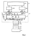
- Figure 1 is a schematic block diagram of a battery powered interface unit forming a modem in accordance with one embodiment of the invention, shown providing a communications link between enclosed electronic equipment and a computer:
- Figure 2 is a schematic circuit diagram of a transmitter incorporated in the circuit of Figure 1:
- Figure 3 is a schematic circuit diagram of a receiver incorporated in the circuit of Figure 2:
- Figure 4 is a diagrammatic front view illustrating the interaction of the interface unit and the enclosed electronic equipment:
- Figure 5 is a sectional side view, partly broken away, of the units shown in Figure 4: and
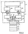
- Figure 6 is a schematic block diagram of a self-powered interface unit forming a modem in accordance with a second embodiment of the invention, shown providing a communications link between enclosed electronic equipment and a computer.
- Referring to Figure 1, a battery powered interface unit 2 provides a modem which forms an interface between a
personal computer 76 and a communications link into or from enclosed electronic equipment 4. The present invention is ideally suited for use with enclosed electronic equipment 4 which is contained in a tamperproof or environmentally sealed casing operating in an adverse environment, for example, acoustic ranging devices manufactured by Milltronics Ltd. which incorporate the invention of U. S. Patent No. 4,821,215. While current models support only one way communication as described in that patent, forthcoming models will support two way communication between the equipment 4 and the interface unit 2, utilizing separate infra-red links of defined geometry. - The interface unit 2 described below provides a modem interfacing between an infra-red or other radiation communications link through a case of the enclosed electronic equipment 4 and the
computer 6. Whilst the presently described embodiments utilizes an infra-red link through the equipment causing the invention herein disclosed may also be implemented using a link effected by visible or other electromagnetic radiation as an alternative to infrared radiation, provided that appropriate transducers, transmitters and receivers are employed, and that at least relevant parts of the enclosure 60 (see Figs. 3 and 4) of the equipment 4 or itslid 62 are transparent to the radiation utilized. Ultrasonic radiation could be used provided that transducers capable of handling appropriate frequencies were utilized: the capabilities of available low cost transducers operating at around 40 kHz are likely to be inadequate to support acceptable serial data rates. - The interface unit 2 includes a first infra-
red transmitter 8 with an associatedinfrared emitting diode 10 and a first infra-red receiver 12 with an associated infra-red sensor diode 14, which form the actual communications interface. The infra-red transmitter 8 andreceiver 12 are powered by apower supply 15 having a positive, negative and ground terminals and powered by abattery 16. The ground terminal of thepower supply 15 is connected to asignal ground pin 20 of a first RS232serial connector 18, having also a transmitteddata pin 22 and a received data pin 24. The transmitteddata pin 22 provides the digital signal voltage to be transmitted to the infra-red transmitter 8 from thecomputer 6. The received data pin 24 receives a digital voltage signal from the infra-red receiver 12. Thetransmitter 8 is also shown as receiving data from anencoding circuit 78 receiving signals from akeypad 54. In practice, the interface unit may either include the keypad and encoder circuit as well as the modem, as shown, or the keyboard and encoder may be omitted, and incorporated into a separate unit similar to that described in U.S. Patent No. 4,821,215, which may be docked as described below in place of the interface unit. - The RS232 (revision C) standard specifies a logic level 0 as represented by any voltage between +3 and +15 volts and a
logic level 1 as represented by any voltage between -3 and -15 volts. Thepower supply 15 is configured to ensure that the voltage level of the signal received on the received data pin 24 is within the specified RS232 tolerance, thereby eliminating the necessity for level shifting the digital voltage signal provided by the first infra-red receiver 12. - The
first RS232 connector 18 is connected to asecond RS232 connector 26, associated with a digital serial interface integral with thecomputer 6. The connection between theRS232 connectors flexible cable 25 having at either end anRS232 connector flexible cable 25 can be chosen to permit thecomputer 6 to be operated outside of the immediate vicinity of the infra-red link into the enclosed electronic equipment 4. - In an alternative embodiment, the first
serial connector 18 may be connected at the end of a flexible cable connected integrally to the interface unit 2. Again, the length of the flexible cable can be chosen so as to permit thecomputer 6 to be operated outside of the immediate vicinity of the enclosed electronic equipment 4. In this case, an additional cable would only be needed in the event that an extension was required to the integral cable. - The enclosed electronic equipment 4 includes
control circuitry 27 implementing the functions performed by the particular unit, for example those described in U.S. Patent No. 4,821,215, and connected thereto is a secondinfrared receiver 28 with an associatedinfrared sensor diode 30. Theinfrared sensor diode 30 can receive data, either modulated or unmodulated, over an optical link from the infra-red source diode 10. Thecontrol circuitry 27 also has connected thereto through a serial interface, a second infra-red transmitter 32 with an associated infra-redemitting diode 34. The infra-redemitting diode 34 is modulated transmit data, either directly or by keying a continuous wave carrier or other technique providing improved noise immunity, to be received bysensor diode 14 over a second optical link. Although the invention is most useful with equipment having both transmitting and receiving capabilities, it may also be used with units which have only one of these capabilities. Thereceiver 28 and thereceiver 32 in the equipment may advantageously be implemented by circuits the same as those used to implement thereceiver 12 and thetransmitter 8, described below with reference to Figures 3 and 2 respectively. - Figure 2 shows a schematic diagram of the
transmitter 8, including its associated infra-redemitting diode 10. A signal from thepin 22 is applied to a limitingamplifier stage 100 which keys anoscillator 102 formed by two NOR gates and associated components and operating at about 375 kHz, the oscillator output being applied through a first input of a NORgate 104 to adriver circuit 106 driving thediode 10. Asecond input 108 of the NORgate 104 receives an input from the keypad encoder circuit 78 (see Fig. 1) if present, in this example produced by keying of a lower frequency of about 40 kHz, otherwise it is strapped to the first input. - In the absence of an input connection from a computer to the
pin 22, that pin will be clamped to a potential near zero by the action of a diode 110 and the base bias circuit of theamplifier 100, and by theresistor 112, therectifier diode 114 and the emitter diode of atransistor 116 in thepower supply 15 with the result that the latter will remain turned off. This in turn maintains aseries pass circuit 118 between thebattery 16 and the remainder of the power supply in a turned off condition. If a computer is connected to the unit through an RS232 compliant serial port, thepin 22 will in a rest condition be held by the computer at a negative potential of at least 3 volts, sufficient to turn on thetransistor 116 and activate the power supply. When signals are passing to the modem at thepin 22, its potential will alternate between negative and positive, but thecapacitor 120 will store sufficient charge rectified bydiode 114 to maintain the series pass circuit in an on condition for the duration of any positive transitions which may occur during the normal transmission of data. - The
power supply 15 further includes a charge pump power supply integratedcircuit 122, for example of type LTC 1044, providing a negative potential B- utilized in thereceiver 12 in addition to the positive potential B+ provided by thecircuit 118. Since the power supply is thus only active when theRS232 port 18 is connected to the RS232 port of a computer, no on/off switch is required for the unit, which will draw no current when not connected to an active RS232 port. - If a similar transmitter is used to implement the
transmitter 32, the functions of the power supply are already implemented within the equipment 4; it may be omitted or left unconnected. - Figure 3 shows a schematic diagram of the
receiver 12 including the infra-red receiving diode 14. Thediode 14 is connected in series with the emitter of a transistor incorporated in acircuit 124 which compensates for differing levels of ambient light which may reach thediode 14 in addition to wanted signals. The circuit acts to provide a regulated supply to the diode which presents very low impedance maintaining a substantially constant potential across the diode responsive to relatively slow ambient light level changes, but presents a relatively much higher impedance responsive to very rapid light level changes such as those produced by high frequency signals such that the latter will produce significant changes in potential across the diode. These are transferred by the lowvalue coupling capacitor 126 to anamplifier 128 andpulse shaping circuit 130 providing pulses, the trailing edges of which are used to trigger a retriggerable monostable multivibrator 132, typically implemented using a 4538 integrated circuit and RC components selected to provide a period of about 4 ms. Anintegrator circuit 134 and a gate connected as abuffer 136 act in conjunction with the monostable multivibrator to demodulate signals keyed at a frequency high enough that sufficient potential can be developed across the integrator to turn on the buffer. This frequency should be sufficiently below the frequency of theoscillator 102 to enable theintegrator circuit 134 to respond quickly, but sufficiently high to exclude unwanted signals. - For example, if the same receiver is utilized for the
receiver 28, it should be capable of excluding and separating signals originating from the keypad from RS232 signals originating from a computer connected to the unit. Whilst the latter, in the example described, are modulated by keying a 375 kHz continuous wave, the former will typically be modulated by keying a 40 kHz (approximately) continuous wave. Such keypad signals can be demodulated by providing anadditional circuit 138 incorporating a monostable multivibrator, integrator and buffer similar to that already described, but using time constants about 10 times greater. This additional circuit is disabled by an output from thebuffer 136 whilst RS232 signals are being received. Thecircuit 138 performs no function in thereceiver 12 and need not be implemented if a similar receiver is not to be used to implement thereceiver 28. - The signal from the
buffer 136 is amplified and level shifted by adriver circuit 140 to provide an RS232 compliant output signal connected to pin 24 if thereceiver 12 is being implemented, or an RS232 input terminal within the equipment 4 if thereceiver 32 is being implemented. - Referring to Figures 4 and 5, a typical embodiment of equipment 4 is shown, in conjunction with the interface 2, which in this case incorporates the
keypad 54 as well as the modem, although as discussed this is an optional feature. The equipment 4 and keypad are generally similar in material respects to those disclosed in U.S. Patent No. 4,821,215 except for incorporation of the modem components shown and described with reference to Figures 1, 2 and 3. - The unit 2, is designed to be portable and to have a portion dockable in a
recess 74 in the enclosed electronic equipment 4. The unit 2 is preferably enclosed in an environmentally sealedcasing 58. The enclosed electronic equipment 4 is enclosed in an environmentally sealedcasing 60, or other casing which is locked or to which access is not readily available, and the infra-red optical links are established through this casing. - Referring to Figure 5, the
diodes window 57, integrally formed with thecasing 58 of the interface unit 2. Thediodes transparent lid 62 of thecasing 60 of the enclosed electronic equipment 4 which is not provided with anopaque backing 68. The windows are of material transparent to the radiation transmitted between thediodes pairs - The interface unit 2 can be releasably retained in place so that part of it enters
recess 74, usingmagnetic strips 76 in the same manner as described in United States Patent No. 4,821,215 with respect to a keypad unit. When the interface unit 2 is docked in the recess, the windows align so that two optical paths are formed: one path betweendiodes diodes windows 38 could be replaced by separate optical fibres in an optical cable, a far end of which is received in a socket in the unit 4 so as to complete optical paths between the fibres and the windows 39. If alternative forms of radiation were used to establish the links, then alternative forms of window or waveguide would be appropriate, which must be effective to prevent significant cross-talk between the channels by controlling the geometry of the optical paths. - A second preferred embodiment of the present invention is shown in Figure 6. For clarity and to facilitate description, those elements common to both Figure 1 and Figure 4 have retained the same numbering.
- The embodiment shown in Figure 4 differs from the embodiment described previously and shown in Figure 1 in that the power supply for the embodiment is obtained from the
computer 6 through theserial connector 26 rather than from a separate battery. An advantage in the use of thecomputer 6 as the power supply is that the interface unit 2 does not then require that provision be made for the replacement or charging of the battery. This embodiment preserves the integrity of the unit 2 and contributes to its portability by reducing its overall weight and size. - An additional advantage to the embodiment shown in Figure 4 is that the
computer 6, unlike the battery, does not require periodic testing to ensure that adequate power is available to power the interface unit 2. However, the power available from the serial interface of a personal computer is limited, and may vary widely according to the implementation of that interface. Moreover, additional circuitry is required in order to implement the interface unit 2. The power available from a battery, on the other hand, can be substantially greater than that available from a portable computer. Such greater power may be desirable to enable a sufficient output from thetransmitter 8 to maintain reliable, noise-immune communication over the infra-red links. - The power source in Figure 6 is derived from the second RS232
serial connector 26, in conjunction with thecomputer 6. In the embodiment shown in Figure 4, thesignal ground pin 20 is used as the positive voltage supply to thetransmitter 8 andreceiver 12 and the transmitteddata pin 22 is connected to a common supply to thetransmitter 8 andreceiver 12 through a diode 44, so that when the transmit pin is in its rest state, typically at -9 volts, a 9 volt supply is available to the transmitter and receiver. The supply is maintained during transmit pulses by areservoir capacitor 48. Alevel shifter 46 is provided at the output of thereceiver 12 in order to ensure that the voltage level of the received signal conforms to the specifications of the serial interface. Conveniently thetransmitter 8 is implemented as a keyed oscillator which is turned on either during or between transmit pulses to generate burst of oscillation used to modulate thediode 10, while thereceiver 12 comprises a tuned amplifier followed by a demodulator and limiting amplifier. The arrangement in which the oscillator is turned on between transmit pulses is preferred, since it then provides a reference signal which can be detected by thereceiver 28 to verify the presence of a link, and which can also be used as an input to an automatic gain control loop used to control the sensitivity of the receiver. - The RS232 serial interface is described with reference to the above preferred embodiments as an example only. Any industry standard bidirectional serial interface either conforming with a standard within the RS232 series, for example revision C or D, or other standard, such as the RS422, RS423 or RS530, could be used to implement the present invention. The RS422 standard for example is implemented in the Macintosh (trademark) computer, and its implementation might be appropriate for use with that brand of computer.
- In one modification, a
bezel 38 of a window for viewing a display of the electronic equipment 4 (see Figure 4) is used to dock the interface unit 2, since the computer connected through the interface will provide an alternative display. In this case, thediodes recess 74 may be omitted.
Claims (8)
- A modem for establishing communication between electronic process control equipment (4) capable of serial data communication, and a personal computer (6) equipped with a standardized general purpose serial data communications port (26), the process control equipment being enclosed within a casing (60) and provided with a serial communications interface implemented by transmission of modulated electromagnetic radiation through a portion (62) of the casing transparent to such radiation, the modem including a serial communications interface (10,14) implemented by transmission of modulated electromagnetic radiation and complementary to that of the process control equipment, characterized in that the modem (2) has a portion configured to be physically interengaged with a complementarily configured portion (62) of the casing of the process control equipment to provide at least one enclosed radiation path, of geometry defined by the interengagement of the portions, between the unit and the equipment, and in that the interface unit further comprises means for establishing plug-in conmunication with a standardized general purpose serial data interface connector of a personal computer, said communication establishing means comprising a serial port connector (18) complementary to that of the computer, means (8) for modulating electrical signals received from the complementary serial port connector (18) to produce modulated electromagnetic radiation for transmission by said complementary serial communications interface (10), and means (12) for demodulating modulated electromagnetic radiation received by said complementary interface (14) to provide electrical signals for application to said complementary serial port connector (18).
- A modem according to claim 1, wherein the electromagnetic radiation is infra-red radiation.
- A modem according to claim 1 or 2, wherein the means (8) for modulating electromagnatic radiation includes a keyed oscillator (102) having a frequency much higher than a highest bit rate to be employed by said serial interface (10,14) and serial port (18).
- A modem according to claim 1, 2 or 3, characterized in that communications interface comprises physically separate means (10,14) for transmitting and receiving radiation, and the configuration of the mating portion of the modem (2) is such as to establish separate enclosed radiation paths (10/30, 34/14) to and from the equipment without significant cross-talk between them.
- A modem according to claim 3, characterized in that it further includes a keypad (54) and a keypad encoder (78) and the means (8) for transmitting radiation to said enclosed electronic equipment is also used to transmit signals from said keypad encoder.
- A modem according to claim 3, wherein the signals from said keypad interface (78) have a carrier frequency much lower than that of a carrier frequency utilized by said modulator (8).
- A modem according to any of the preceding claims, including a battery (16), a power supply (15) providing power from said battery to said modem, characterized in that it includes a circuit (112-120) responding to connect of the complementary serial port connector (18) to a serial port connector (26) of a computer (6) to turn on said power supply (15).
- A modem according to claim 7, characterized in that the response circuit includes a rectifier (114) rectifying a negative potential appearing on a transmit pin (22) of said complementary port connector, and a switching transistor (116) turned on by an output of said rectifier stored by a capacitor (120).
Applications Claiming Priority (3)
| Application Number | Priority Date | Filing Date | Title |
|---|---|---|---|
| US91453192A | 1992-07-17 | 1992-07-17 | |
| US914531 | 1992-07-17 | ||
| PCT/CA1993/000295 WO1994002901A1 (en) | 1992-07-17 | 1993-07-16 | Modem for communicating with enclosed electronic equipment |
Publications (2)
| Publication Number | Publication Date |
|---|---|
| EP0650617A1 EP0650617A1 (en) | 1995-05-03 |
| EP0650617B1 true EP0650617B1 (en) | 1996-11-06 |
Family
ID=25434483
Family Applications (1)
| Application Number | Title | Priority Date | Filing Date |
|---|---|---|---|
| EP93915608A Expired - Lifetime EP0650617B1 (en) | 1992-07-17 | 1993-07-16 | Modem for communicating with enclosed electronic equipment |
Country Status (13)
| Country | Link |
|---|---|
| EP (1) | EP0650617B1 (en) |
| JP (1) | JPH08502373A (en) |
| KR (1) | KR950702722A (en) |
| AT (1) | ATE145074T1 (en) |
| AU (1) | AU666210B2 (en) |
| CA (1) | CA2140261C (en) |
| DE (1) | DE69305857T2 (en) |
| DK (1) | DK0650617T3 (en) |
| ES (1) | ES2096303T3 (en) |
| NZ (1) | NZ254045A (en) |
| RU (1) | RU2109332C1 (en) |
| WO (1) | WO1994002901A1 (en) |
| ZA (1) | ZA935198B (en) |
Families Citing this family (2)
| Publication number | Priority date | Publication date | Assignee | Title |
|---|---|---|---|---|
| JPH08118251A (en) * | 1994-10-19 | 1996-05-14 | Tonichi Seisakusho:Kk | Data transfer device in torque wrench |
| DE19929193A1 (en) * | 1999-06-27 | 2000-12-28 | Geze Gmbh | Escape and rescue route device has magnetic and/or electromechanical locking device, local and/or central controller(s), service terminal with wireless data interface communications device |
Family Cites Families (7)
| Publication number | Priority date | Publication date | Assignee | Title |
|---|---|---|---|---|
| BE786584A (en) * | 1971-07-21 | 1973-01-22 | Rhone Poulenc Sa | MICROPOROUS MEMBRANES IN PHENOLIC POLYETHERS |
| US4119948A (en) * | 1976-04-29 | 1978-10-10 | Ernest Michael Ward | Remote meter reading system |
| DE3232015C2 (en) * | 1982-08-27 | 1986-07-17 | Siemens AG, 1000 Berlin und 8000 München | Data transmission system |
| US4775928A (en) * | 1985-10-30 | 1988-10-04 | Westinghouse Electric Corp. | Hand-held wireless computer controller system |
| US4821215A (en) * | 1986-10-03 | 1989-04-11 | Canadian Corporate Management Company Limited | Monitoring equipment for adverse environments |
| SU1481783A1 (en) * | 1987-10-26 | 1989-05-23 | Предприятие П/Я М-5308 | Multichannel unit for connecting subscribers to common bus |
| SU1605246A1 (en) * | 1987-12-08 | 1990-11-07 | Предприятие П/Я А-3327 | Electronic module to communication line interface |
-
1993
- 1993-07-16 DK DK93915608.9T patent/DK0650617T3/en active
- 1993-07-16 DE DE69305857T patent/DE69305857T2/en not_active Expired - Lifetime
- 1993-07-16 RU RU95107693A patent/RU2109332C1/en active
- 1993-07-16 NZ NZ254045A patent/NZ254045A/en unknown
- 1993-07-16 EP EP93915608A patent/EP0650617B1/en not_active Expired - Lifetime
- 1993-07-16 AT AT93915608T patent/ATE145074T1/en not_active IP Right Cessation
- 1993-07-16 ES ES93915608T patent/ES2096303T3/en not_active Expired - Lifetime
- 1993-07-16 JP JP6504046A patent/JPH08502373A/en active Pending
- 1993-07-16 WO PCT/CA1993/000295 patent/WO1994002901A1/en not_active Ceased
- 1993-07-16 CA CA002140261A patent/CA2140261C/en not_active Expired - Fee Related
- 1993-07-16 AU AU45556/93A patent/AU666210B2/en not_active Ceased
- 1993-07-16 KR KR1019950700154A patent/KR950702722A/en not_active Ceased
- 1993-07-19 ZA ZA935198A patent/ZA935198B/en unknown
Also Published As
| Publication number | Publication date |
|---|---|
| KR950702722A (en) | 1995-07-29 |
| JPH08502373A (en) | 1996-03-12 |
| AU4555693A (en) | 1994-02-14 |
| RU2109332C1 (en) | 1998-04-20 |
| ES2096303T3 (en) | 1997-03-01 |
| AU666210B2 (en) | 1996-02-01 |
| NZ254045A (en) | 1996-11-26 |
| CA2140261A1 (en) | 1994-02-03 |
| ZA935198B (en) | 1994-04-21 |
| EP0650617A1 (en) | 1995-05-03 |
| WO1994002901A1 (en) | 1994-02-03 |
| ATE145074T1 (en) | 1996-11-15 |
| CA2140261C (en) | 1999-03-16 |
| DE69305857D1 (en) | 1996-12-12 |
| DE69305857T2 (en) | 1997-04-10 |
| DK0650617T3 (en) | 1997-04-14 |
Similar Documents
| Publication | Publication Date | Title |
|---|---|---|
| US5519527A (en) | Modem for communicating with enclosed electronic equipment | |
| US5157769A (en) | Computer data interface for handheld computer transfer to second computer including cable connector circuitry for voltage modification | |
| US9602167B2 (en) | Remote energy transfer system | |
| JP2788135B2 (en) | Automatic pulse reading and recording device | |
| US6819866B2 (en) | Watertight universal housing | |
| US4578874A (en) | Prober with optical transmission scheme | |
| US4580295A (en) | System for monitoring optical data bus transmissions | |
| US5218466A (en) | Communication device with optical communication interface | |
| IE55512B1 (en) | Storing data relating to television viewing | |
| US4847595A (en) | Alarm system | |
| CZ284613B6 (en) | Communication adapter for matching an electric communication port to optical communication port | |
| US4943799A (en) | Portable alarm system with sealed enclosure | |
| AU9001191A (en) | A system and method for the non-contact transmission of data | |
| AU666210B2 (en) | Modem for communicating with enclosed electronic equipment | |
| US5929425A (en) | Portable wireless optical scanner with user interface mounted on charger | |
| JPH0281114A (en) | Cordless keyboard | |
| CA2381865A1 (en) | Method and apparatus for allowing or disrupting passage of power in electrical appliances | |
| US3315263A (en) | Remote-control device | |
| EP0987646A2 (en) | RFID reader/writer device | |
| US4810891A (en) | Method for the automatic identification of the type of measuring head of a fiber optic measurement value acquisition and transmission device | |
| US5528233A (en) | Optical service tool apparatus | |
| JPS55115755A (en) | Failure detector for data highway | |
| EP1954889B1 (en) | A control panel and receptacle for an earth moving equipment | |
| US6603387B1 (en) | Programming of RF transmitter identification data by monitoring power | |
| KR200365979Y1 (en) | Automatic protection apparatus for unattended computer |
Legal Events
| Date | Code | Title | Description |
|---|---|---|---|
| PUAI | Public reference made under article 153(3) epc to a published international application that has entered the european phase |
Free format text: ORIGINAL CODE: 0009012 |
|
| 17P | Request for examination filed |
Effective date: 19950203 |
|
| AK | Designated contracting states |
Kind code of ref document: A1 Designated state(s): AT BE CH DE DK ES FR GB GR IE IT LI LU NL PT SE |
|
| GRAG | Despatch of communication of intention to grant |
Free format text: ORIGINAL CODE: EPIDOS AGRA |
|
| 17Q | First examination report despatched |
Effective date: 19951221 |
|
| GRAH | Despatch of communication of intention to grant a patent |
Free format text: ORIGINAL CODE: EPIDOS IGRA |
|
| GRAH | Despatch of communication of intention to grant a patent |
Free format text: ORIGINAL CODE: EPIDOS IGRA |
|
| GRAA | (expected) grant |
Free format text: ORIGINAL CODE: 0009210 |
|
| AK | Designated contracting states |
Kind code of ref document: B1 Designated state(s): AT BE CH DE DK ES FR GB GR IE IT LI LU NL PT SE |
|
| PG25 | Lapsed in a contracting state [announced via postgrant information from national office to epo] |
Ref country code: GR Free format text: LAPSE BECAUSE OF FAILURE TO SUBMIT A TRANSLATION OF THE DESCRIPTION OR TO PAY THE FEE WITHIN THE PRESCRIBED TIME-LIMIT Effective date: 19961106 |
|
| REF | Corresponds to: |
Ref document number: 145074 Country of ref document: AT Date of ref document: 19961115 Kind code of ref document: T |
|
| REG | Reference to a national code |
Ref country code: IE Ref legal event code: FG4D Free format text: 70570 |
|
| REF | Corresponds to: |
Ref document number: 69305857 Country of ref document: DE Date of ref document: 19961212 |
|
| REG | Reference to a national code |
Ref country code: CH Ref legal event code: NV Representative=s name: A. BRAUN, BRAUN, HERITIER, ESCHMANN AG PATENTANWAE |
|
| ITF | It: translation for a ep patent filed | ||
| PG25 | Lapsed in a contracting state [announced via postgrant information from national office to epo] |
Ref country code: PT Effective date: 19970206 |
|
| ET | Fr: translation filed | ||
| REG | Reference to a national code |
Ref country code: ES Ref legal event code: FG2A Ref document number: 2096303 Country of ref document: ES Kind code of ref document: T3 |
|
| REG | Reference to a national code |
Ref country code: DK Ref legal event code: T3 |
|
| PG25 | Lapsed in a contracting state [announced via postgrant information from national office to epo] |
Ref country code: IE Free format text: LAPSE BECAUSE OF NON-PAYMENT OF DUE FEES Effective date: 19970716 |
|
| PGFP | Annual fee paid to national office [announced via postgrant information from national office to epo] |
Ref country code: CH Payment date: 19970725 Year of fee payment: 5 |
|
| PG25 | Lapsed in a contracting state [announced via postgrant information from national office to epo] |
Ref country code: LU Free format text: LAPSE BECAUSE OF NON-PAYMENT OF DUE FEES Effective date: 19970731 |
|
| PLBE | No opposition filed within time limit |
Free format text: ORIGINAL CODE: 0009261 |
|
| STAA | Information on the status of an ep patent application or granted ep patent |
Free format text: STATUS: NO OPPOSITION FILED WITHIN TIME LIMIT |
|
| 26N | No opposition filed | ||
| PGFP | Annual fee paid to national office [announced via postgrant information from national office to epo] |
Ref country code: DK Payment date: 19980724 Year of fee payment: 6 |
|
| PGFP | Annual fee paid to national office [announced via postgrant information from national office to epo] |
Ref country code: BE Payment date: 19980729 Year of fee payment: 6 |
|
| PGFP | Annual fee paid to national office [announced via postgrant information from national office to epo] |
Ref country code: AT Payment date: 19980730 Year of fee payment: 6 |
|
| PG25 | Lapsed in a contracting state [announced via postgrant information from national office to epo] |
Ref country code: LI Free format text: LAPSE BECAUSE OF NON-PAYMENT OF DUE FEES Effective date: 19980731 Ref country code: CH Free format text: LAPSE BECAUSE OF NON-PAYMENT OF DUE FEES Effective date: 19980731 |
|
| PGFP | Annual fee paid to national office [announced via postgrant information from national office to epo] |
Ref country code: ES Payment date: 19980731 Year of fee payment: 6 |
|
| REG | Reference to a national code |
Ref country code: CH Ref legal event code: PL |
|
| PG25 | Lapsed in a contracting state [announced via postgrant information from national office to epo] |
Ref country code: AT Free format text: LAPSE BECAUSE OF NON-PAYMENT OF DUE FEES Effective date: 19990716 |
|
| PG25 | Lapsed in a contracting state [announced via postgrant information from national office to epo] |
Ref country code: ES Free format text: LAPSE BECAUSE OF NON-PAYMENT OF DUE FEES Effective date: 19990717 |
|
| PG25 | Lapsed in a contracting state [announced via postgrant information from national office to epo] |
Ref country code: BE Free format text: LAPSE BECAUSE OF NON-PAYMENT OF DUE FEES Effective date: 19990731 |
|
| PG25 | Lapsed in a contracting state [announced via postgrant information from national office to epo] |
Ref country code: DK Free format text: LAPSE BECAUSE OF NON-PAYMENT OF DUE FEES Effective date: 19990802 |
|
| BERE | Be: lapsed |
Owner name: MILLTRONICS LTD Effective date: 19990731 |
|
| REG | Reference to a national code |
Ref country code: DK Ref legal event code: EBP |
|
| PGFP | Annual fee paid to national office [announced via postgrant information from national office to epo] |
Ref country code: GB Payment date: 20000717 Year of fee payment: 8 |
|
| PGFP | Annual fee paid to national office [announced via postgrant information from national office to epo] |
Ref country code: SE Payment date: 20000725 Year of fee payment: 8 |
|
| PGFP | Annual fee paid to national office [announced via postgrant information from national office to epo] |
Ref country code: NL Payment date: 20000731 Year of fee payment: 8 Ref country code: FR Payment date: 20000731 Year of fee payment: 8 |
|
| PG25 | Lapsed in a contracting state [announced via postgrant information from national office to epo] |
Ref country code: GB Free format text: LAPSE BECAUSE OF NON-PAYMENT OF DUE FEES Effective date: 20010716 |
|
| PG25 | Lapsed in a contracting state [announced via postgrant information from national office to epo] |
Ref country code: SE Free format text: LAPSE BECAUSE OF NON-PAYMENT OF DUE FEES Effective date: 20010717 |
|
| PG25 | Lapsed in a contracting state [announced via postgrant information from national office to epo] |
Ref country code: NL Free format text: LAPSE BECAUSE OF NON-PAYMENT OF DUE FEES Effective date: 20020201 |
|
| EUG | Se: european patent has lapsed |
Ref document number: 93915608.9 |
|
| GBPC | Gb: european patent ceased through non-payment of renewal fee |
Effective date: 20010716 |
|
| PG25 | Lapsed in a contracting state [announced via postgrant information from national office to epo] |
Ref country code: FR Free format text: LAPSE BECAUSE OF NON-PAYMENT OF DUE FEES Effective date: 20020329 |
|
| NLV4 | Nl: lapsed or anulled due to non-payment of the annual fee |
Effective date: 20020201 |
|
| REG | Reference to a national code |
Ref country code: FR Ref legal event code: ST |
|
| REG | Reference to a national code |
Ref country code: ES Ref legal event code: FD2A Effective date: 20020603 |
|
| PG25 | Lapsed in a contracting state [announced via postgrant information from national office to epo] |
Ref country code: IT Free format text: LAPSE BECAUSE OF NON-PAYMENT OF DUE FEES Effective date: 20050716 |
|
| REG | Reference to a national code |
Ref country code: DE Ref legal event code: R082 Ref document number: 69305857 Country of ref document: DE |
|
| REG | Reference to a national code |
Ref country code: DE Ref legal event code: R081 Ref document number: 69305857 Country of ref document: DE Owner name: SIEMENS AKTIENGESELLSCHAFT, DE Free format text: FORMER OWNER: SIEMENS MILLTRONICS PROCESS INSTRUMENTS INC., PETERBOROUGH, CA Effective date: 20120109 |
|
| PGFP | Annual fee paid to national office [announced via postgrant information from national office to epo] |
Ref country code: DE Payment date: 20120906 Year of fee payment: 20 |
|
| REG | Reference to a national code |
Ref country code: DE Ref legal event code: R071 Ref document number: 69305857 Country of ref document: DE |
|
| PG25 | Lapsed in a contracting state [announced via postgrant information from national office to epo] |
Ref country code: DE Free format text: LAPSE BECAUSE OF EXPIRATION OF PROTECTION Effective date: 20130717 |