EP0650089B1 - High resolution radiographic recording element - Google Patents
High resolution radiographic recording element Download PDFInfo
- Publication number
- EP0650089B1 EP0650089B1 EP94115125A EP94115125A EP0650089B1 EP 0650089 B1 EP0650089 B1 EP 0650089B1 EP 94115125 A EP94115125 A EP 94115125A EP 94115125 A EP94115125 A EP 94115125A EP 0650089 B1 EP0650089 B1 EP 0650089B1
- Authority
- EP
- European Patent Office
- Prior art keywords
- carbons
- alkyl
- aryl
- intensifying screen
- combinations
- Prior art date
- Legal status (The legal status is an assumption and is not a legal conclusion. Google has not performed a legal analysis and makes no representation as to the accuracy of the status listed.)
- Expired - Lifetime
Links
Images

Classifications
-
- C—CHEMISTRY; METALLURGY
- C09—DYES; PAINTS; POLISHES; NATURAL RESINS; ADHESIVES; COMPOSITIONS NOT OTHERWISE PROVIDED FOR; APPLICATIONS OF MATERIALS NOT OTHERWISE PROVIDED FOR
- C09B—ORGANIC DYES OR CLOSELY-RELATED COMPOUNDS FOR PRODUCING DYES, e.g. PIGMENTS; MORDANTS; LAKES
- C09B23/00—Methine or polymethine dyes, e.g. cyanine dyes
- C09B23/02—Methine or polymethine dyes, e.g. cyanine dyes the polymethine chain containing an odd number of >CH- or >C[alkyl]- groups
- C09B23/04—Methine or polymethine dyes, e.g. cyanine dyes the polymethine chain containing an odd number of >CH- or >C[alkyl]- groups one >CH- group, e.g. cyanines, isocyanines, pseudocyanines
-
- C—CHEMISTRY; METALLURGY
- C09—DYES; PAINTS; POLISHES; NATURAL RESINS; ADHESIVES; COMPOSITIONS NOT OTHERWISE PROVIDED FOR; APPLICATIONS OF MATERIALS NOT OTHERWISE PROVIDED FOR
- C09B—ORGANIC DYES OR CLOSELY-RELATED COMPOUNDS FOR PRODUCING DYES, e.g. PIGMENTS; MORDANTS; LAKES
- C09B23/00—Methine or polymethine dyes, e.g. cyanine dyes
- C09B23/0091—Methine or polymethine dyes, e.g. cyanine dyes having only one heterocyclic ring at one end of the methine chain, e.g. hemicyamines, hemioxonol
-
- C—CHEMISTRY; METALLURGY
- C09—DYES; PAINTS; POLISHES; NATURAL RESINS; ADHESIVES; COMPOSITIONS NOT OTHERWISE PROVIDED FOR; APPLICATIONS OF MATERIALS NOT OTHERWISE PROVIDED FOR
- C09K—MATERIALS FOR MISCELLANEOUS APPLICATIONS, NOT PROVIDED FOR ELSEWHERE
- C09K11/00—Luminescent materials, e.g. electroluminescent or chemiluminescent
- C09K11/02—Use of particular materials as binders, particle coatings or suspension media therefor
- C09K11/025—Use of particular materials as binders, particle coatings or suspension media therefor non-luminescent particle coatings or suspension media
-
- C—CHEMISTRY; METALLURGY
- C09—DYES; PAINTS; POLISHES; NATURAL RESINS; ADHESIVES; COMPOSITIONS NOT OTHERWISE PROVIDED FOR; APPLICATIONS OF MATERIALS NOT OTHERWISE PROVIDED FOR
- C09K—MATERIALS FOR MISCELLANEOUS APPLICATIONS, NOT PROVIDED FOR ELSEWHERE
- C09K11/00—Luminescent materials, e.g. electroluminescent or chemiluminescent
- C09K11/08—Luminescent materials, e.g. electroluminescent or chemiluminescent containing inorganic luminescent materials
-
- G—PHYSICS
- G03—PHOTOGRAPHY; CINEMATOGRAPHY; ANALOGOUS TECHNIQUES USING WAVES OTHER THAN OPTICAL WAVES; ELECTROGRAPHY; HOLOGRAPHY
- G03C—PHOTOSENSITIVE MATERIALS FOR PHOTOGRAPHIC PURPOSES; PHOTOGRAPHIC PROCESSES, e.g. CINE, X-RAY, COLOUR, STEREO-PHOTOGRAPHIC PROCESSES; AUXILIARY PROCESSES IN PHOTOGRAPHY
- G03C5/00—Photographic processes or agents therefor; Regeneration of such processing agents
- G03C5/16—X-ray, infrared, or ultraviolet ray processes
- G03C5/17—X-ray, infrared, or ultraviolet ray processes using screens to intensify X-ray images
-
- G—PHYSICS
- G21—NUCLEAR PHYSICS; NUCLEAR ENGINEERING
- G21K—HANDLING OF PARTICLES OR IONISING RADIATION NOT OTHERWISE PROVIDED FOR; IRRADIATION DEVICES; GAMMA RAY OR X-RAY MICROSCOPES
- G21K4/00—Conversion screens for the conversion of the spatial distribution of X-rays or particle radiation into visible images, e.g. fluoroscopic screens
-
- G—PHYSICS
- G21—NUCLEAR PHYSICS; NUCLEAR ENGINEERING
- G21K—HANDLING OF PARTICLES OR IONISING RADIATION NOT OTHERWISE PROVIDED FOR; IRRADIATION DEVICES; GAMMA RAY OR X-RAY MICROSCOPES
- G21K4/00—Conversion screens for the conversion of the spatial distribution of X-rays or particle radiation into visible images, e.g. fluoroscopic screens
- G21K2004/04—Conversion screens for the conversion of the spatial distribution of X-rays or particle radiation into visible images, e.g. fluoroscopic screens with an intermediate layer
-
- G—PHYSICS
- G21—NUCLEAR PHYSICS; NUCLEAR ENGINEERING
- G21K—HANDLING OF PARTICLES OR IONISING RADIATION NOT OTHERWISE PROVIDED FOR; IRRADIATION DEVICES; GAMMA RAY OR X-RAY MICROSCOPES
- G21K4/00—Conversion screens for the conversion of the spatial distribution of X-rays or particle radiation into visible images, e.g. fluoroscopic screens
- G21K2004/06—Conversion screens for the conversion of the spatial distribution of X-rays or particle radiation into visible images, e.g. fluoroscopic screens with a phosphor layer
-
- G—PHYSICS
- G21—NUCLEAR PHYSICS; NUCLEAR ENGINEERING
- G21K—HANDLING OF PARTICLES OR IONISING RADIATION NOT OTHERWISE PROVIDED FOR; IRRADIATION DEVICES; GAMMA RAY OR X-RAY MICROSCOPES
- G21K4/00—Conversion screens for the conversion of the spatial distribution of X-rays or particle radiation into visible images, e.g. fluoroscopic screens
- G21K2004/10—Conversion screens for the conversion of the spatial distribution of X-rays or particle radiation into visible images, e.g. fluoroscopic screens with a protective film
Definitions
- This invention is related to the field of medical radiography. More specifically this invention is related to an X-ray intensifying screen which emits primarily ultraviolet radiation and to a radiographic element comprising said X-ray intensifying screen.
- Radiography has been exploited for many years as a means for visualizing and diagnosing internal, possibly pathological, structures in living organisms.
- a patient is typically exposed to X-rays which are selectively and partially absorbed by tissues and bones as they pass through the patient.
- the X-radiation which thus passes partially attenuated through the patient, carries information about the patients internal structure.
- Efforts aiming to capture and display this information with the highest degree of accuracy, minimal loss of information content and minimal patient exposure constitute the basis for a large part of the research effort in radiography.
- Modern medical radiography systems typically utilize one or two phosphor intensifying screens which absorb X-rays and emit visible or ultraviolet light, thus translating the information initially carried by the X-ray beam to information carried by longer wavelength radiation.
- This longer wavelength image then impinges on a photographic element sensitive to the actinic light emitted by the intensifying screen or screens.
- This photographic element comprises one or two photosensitive elements coated on either side of a support. Upon absorbing the actinic light emitted by the intensifying screen or screens a latent image is formed in the photographic element, thus rendering the photographic element developable and allowing an image of the information originally carried by the X-ray beam to be recorded as a permanent image.
- light scattering coupled with internal light absorption actually improves the screens' ability to faithfully reproduce the information carried by the X-ray beam, in that it improves the screens' ability to resolve fine details, i.e., by improving the screens' resolution as determined by its Modulation Transfer Function (MTF).
- MTF Modulation Transfer Function
- EP-A-0 028 521 discloses green-emitting X-ray intensifying screens having a phosphor layer which comprises a phosphor having at least one major green emission maximum in the wavelength range between 500 and 600 nm and at least one major blue emission maximum in the wavelength range between 300 and 500 nm and having at least 30 percent of its emission above 500 nm.
- UV emitting screen provides superior resolution compared to screens which emit blue or green light. This is partially due to absorption of UV light by the film base and partly due to the decreased path length for absorption of UV light in the screen itself. This has resulted in the development of film/screen systems wherein the screen emits primarily UV light and the film is most sensitive to UV light emitted by the screen.
- Phosphors have long been available which emit in the UV when excited with X-radiation. Some of these, particularly YTaO 4 , emit primarily in the UV and are eminently suitable for use in an X-ray intensifying screen. Others, such as terbium activated lanthanum oxyhalide have excellent X-ray absorption properties and X-ray to light conversion efficiencies, yet they emit visible, blue and UV light. The visible emission is known to be detrimental to resolution and therefore these phosphors have limited utility for ultrahigh resolution imaging. There has been a persistent need in the art to provide an X-ray intensifying screen which has excellent X-ray to light conversion properties and emits virtually exclusively in the ultraviolet region of the electromagnetic spectrum.
- a particular feature of the present invention is the ability to adapt phosphors which emit visible and ultra-violet light into a screen which emits primarily ultraviolet light by the inclusion of a dye which attenuates the visible emission.
- the present invention provides
- At least 80 % of the radiation emitted from the X-ray intensifying screen has a wavelength of less than 400 nm.
- Fig. 1 shows a modern mammography exposure unit.
- the object to be examined, 1, is localized between a compression plate, 2, and an exposure grid, 3.
- X-radiation, 4 emanates from an x-ray source, 5, and transits through the substantially transparent compression plate, 2, prior to irradiating the object to be examined.
- the first phenomenon is scatter, as represented by 6.
- Scattered radiation is substantially attenuated by the grid, 3, while primary, non-scattered radiation passes through the grid largely unattenuated.
- the radiation is selectively absorbed within the object to be examined, thereby forming an imagewise x-ray intensity modulation which corresponds to structural variations within the object being examined.
- a conventional radiographic element is similar to a mammographic exposure unit with the exception of the absence of a compression plate and the possible addition of a table, or bed, between the object being examined and the grid.
- Fig. 2 shows an expanded view of the radiographic element, 7.
- the film element, 8, is situated between the front intensifying screen, 9, and the back intensifying screen, 10.
- the exposure source is represented by the arrow, 11.
- the film element comprises a support, 12, with subbing layers, 13 and 14.
- Photosensitive layers 15, 16 are coated on the subbing layers.
- the front intensifying screen element, 9, comprises a support, 19, with an interlayer, 20, coated thereon. Below the interlayer, 20, is a phosphor layer, 21, comprising a phosphor and a binder. Optional, yet preferred, is a protective layer, 22.
- the back intensifying screen, 10, is analogous to the front intensifying screen, 9, with a support, 23, interlayer, 24, phosphor layer, 25, which comprises a phosphor and a binder and an optional, yet preferred protective layer, 26.
- the phosphor layer, protective layer, or both contain a dye suitable for attenuating the emissions above 400 nm.
- the front intensifying screen, 9, back intensifying screen, 10, and film element, 8, are typically contained in a reusable cassette, as known in the art, which is fashioned such that the film element can be easily replaced after each exposure.
- the acutance dye is chosen such that its absorption of visible light (>400 nm) is high and its absorption of UV light ( ⁇ 400 nm) is low.
- Particularly suitable are acutance dyes defined by the general formula:
- the five or six membered ring, or substituted five or six membered ring may be broadly described provided the above mentioned properties are not compromised.
- the ring may be substituted of unsubstituted.
- Exemplary rings structures within the teachings of the invention are cycloalkyl, cycloalkenyl, indoles, piperidine, piperidyl, piperazinyl, pyrrolidine, pyrrolidinyl, pyrazolidine, pyrimidine, furan, thiophene, oxazine, barbituric acid, thiobarbituric acid, and rhodanine.
- moieties are derived from the following nuclei which may be additionally substituted if so desired: 1,3-indanedione, pyrazolorie, 2,4,6,-trioxohexahydropyrimidine, 2-thio-4,6,dioxohexahydropyrimidine, 3,5-pyrazolidinedione, 5,7-dioxo-6,7-dihydro-5-thiazolo[3,2-a]pyrimidine, 2-thio-2,4-oxazolidinedione, 5,5-dialkyl-1,3-cylcohexanedione and 2-hydroxy-4H-pyrido[1,2-a]pyrimidin-4-one.
- aryl, alkyl, five membered ring and six membered ring refer to moieties which may be unsubstituted or substituted with halogen, alcohol, amines, thiols, alkyl, aryl, ethers, carboxyls, sulfonates, sulfonamides, amides and esters.
- Particularly preferred phosphors are chosen from:
- activators are specified in the chemical formula of a phosphor as :X, for activator X.
- Activators are typically added in an amount of up to 20% by weight and preferably 10% by weight.
- an intensifying screen comprises a support, an intensifying phosphor layer, and a topcoat or protective layer thereon.
- a reflective layer such as a whitener (e.g. TiO 2 dispersed in a suitable binder) may also be added into the screen structure. Commonly, this reflective layer is interposed between the phosphor layer and the support, or, alternatively, the whitener may be dispersed directly in the support. In operation, the reflective layer generally increases the light output of the intensifying screen.
- the protective layer is important to protect the phosphor layer against mechanical damage.
- the protective layer should also be UV transparent. Those protective layers that are known to strongly absorb UV light (e.g. polyethylene terephthalate films) are not particularly useful within this invention.
- the intensifying screen absorbs X-rays that impinge thereon and emits light having a wavelength that is actinic with respect to the photographic silver halide X-ray film associated therewith.
- the screens of this invention emit at least 70 % of their light below 400 nm. Most preferred is a screen which emits at least 80 % of its light below 400 nm.
- Phosphors are generally manufactured by mixing the various oxides and firing in a suitable flux at elevated temperatures.
- the phosphor After firing, pulverizing and washing, the phosphor is mixed with a suitable binder in the presence of a suitable solvent and coated on a support. All of these steps are well-known in the prior art. A protective topcoat may also be applied over this phosphor coating, in fact it is preferred. For example, the phosphor may be coated to a coating weight of ca. 15 to 110 mg of phosphor per cm 2 . A topcoat of styrene/acrylonitrile copolymer is coated thereon and dried.
- an X-ray intensifying screen is made by dispersing LaOBr:Tm phosphor made as described above, in a mixture of acrylic resins using a solvent. This mixture is then coated on a polyethylene terephthalate support containing a small amount of anatase TiO 2 whitener dispersed therein.
- Calcium tungstate phosphors are taught by Wynd, et.al., U. S. Pat. No. 2,303,942.
- Niobium-activated and rare earth-activated yttrium, lutetium, and gadolinium tantalates are taught by Brixner, U.S. Pat. No. 4,225,653.
- Rare earth-activated gadolinium and yttrium middle chalcogen phosphors are taught by Royce, et.al., U.S. Pat. No. 3,418,246.
- Rare earth-activated lanthanum and lutetium middle chalcogen phosphors are illustrated by Yocum, U.S. Pat. No. 3,418,247.
- Terbium-activated lanthanum, gadolinium and lutetium oxysulfide phosphors are illustrated by Buchanan, et.al. U.S. Pat. No. 3,725,704. Cerium-activated lanthanum oxychloride phosphors are taught by Swindells U.S. Pat. No. 2,729,604. Terbium-activated and optionally cerium-activated lanthanum and gadolinium oxyhalide phosphors are disclosed by Rabatin U.S. Pat. No. 3,617,743 and Ferri, et.al., U.S. Pat. No. 3,974,389.
- Rare earth-activated rare earth oxyhalide phosphors are taught by Rabatin U.S. Pat. Nos. 3,591,516 and 3,607,770.
- Terbium-activated and ytterbium-activated rare earth oxyhalide phosphors are taught by Rabatin, U.S. Pat. No. 3,666,676.
- Thulium-activated lanthanum oxychloride or oxybromide phosphors are taught by Rabatin U.S. Pat. No. 3,795,814.
- a (Y,Gd)2O2S:Tb phosphor wherein the ratio of yttrium to gadolinium is between 93:7 and 97:3 is taught by Yale, U.S. Pat. No.
- Non-rare earth coactivators such bismuth and ytterbium-activated lanthanum oxychloride phosphors are taught by Luckey, et.al., U.S. Pat. No. 4,311,487. Titanium activated zirconium and hafnium oxide phosphors are taught by Bryan, et.al., U.S. Pat. No. 5,095,218. Europium activated barium flourohalide phosphor wherein a portion of barium is replaced with an alkali metal and a trivalent metal are taught in Umemoto, et.al., U.S. Pat. No. 5,089,170.
- Titanium activated and unactivated hafnium zirconium germanate phosphors are taught in Lambert, et.al., U.S. Pat. No. 5,112,700.
- Magnesium tantalum niobium oxide phosphors are taught in Sieber, et.al., U.S. Pat. No. 5,132,192.
- Hafnium zirconium phosphors are taught by Bryan, et.al., U.S. Pat. Nos. 4,996,003; 4,988,880 and 4,988,881.
- the mixing of phosphors as well as the coating of phosphors in separate layers of the same screen are recognized. Specific examples include mixtures of calcium tungstate and yttrium tantalate as illustrated by Patten, U.S. Pat. No. 4,387,141.
- the phosphors may be prepared as is well-known in the art and then mixed with a suitable binder before coating on a suitable support. Once prepared in this manner, this element is conventionally known as an X-ray intensifying screen and is eminently suitable for radiological examinations.
- Medical X-ray film processing is well documented in the art as exemplified in Wuelfing, U. S. Patent 4,741,991.
- a medical X-ray film to be processed is developed to convert latent image centers within the silver halide grain into elemental silver. Unreacted silver halide is then removed by dissolving in a suitable fixer and the film is washed and dried to provide a final image.
- the silver halide element will be comprised of silver halide grains. These element are also well-known in the prior art and the preparation of grains is also known and taught therein.
- the grains are generally suspended in an emulsion using a binder such as gelatin, and are sensitized with gold and sulfur, for example.
- Other adjuvants such as antifoggants, wetting and coating aides, sensitizing dyes, hardeners etc. may also be present if necessary.
- the emulsion may be double-side coated on the support and a thin, hardened gelatin overcoat is usually applied over each of the emulsion layers to provide protection thereto. Since the emulsions useful within the ambit of this invention are generally UV sensitive in and of themselves, spectral sensitizing dyes may not be required. However, if required, a small amount of a sensitizing dye might advantageously be added as exemplified in U.S. Pat. Nos. 5,108,887 and 5,169,748. Additionally, it is also conventional to add a sensitizing dye to tabular emulsions in order to increase their ability to respond to light.
- the silver halide emulsion may employ any of the conventional halides, but preferred are pure silver bromide or silver bromide with small amounts of iodide incorporated therein (e.g. 98% Br and 2% I by weight for example). Any grain morphology is suitable for demonstration of these teachings, including, but not limited to, grains which are formed by splash techniques and those formed by spray techniques (i.e. single and double jet procedures). Tabular grains are most preferred.
- Tabular grain silver halide products are well-known in the prior art with exemplary methods of manufacture described by Maskasky in U.S. 4,400,463; Wey, U.S. 4,399,205; Dickerson, U.S. 4,414,304; Wilgus et al., U.S. 4,434,226; Kofron et al., U.S. 4,439,520; Nottorf, U.S. 4,722,886; and Ellis, U.S. 4,801,522.
- a binder e.g. gelatin or other well-known binders such as polyvinyl alcohol, phthalated gelatins, etc.
- a binder e.g. gelatin or other well-known binders such as polyvinyl alcohol, phthalated gelatins, etc.
- gelatin other natural or synthetic water-permeable organic colloid binding agents can be used as a total or partial replacement thereof.
- Such agents include water permeable or water-soluble polyvinyl alcohol and its derivatives, e.g., partially hydrolyzed polyvinyl acetates, polyvinyl ethers, and acetals containing a large number of extralinear -CH 2 CHOH- groups; hydrolyzed interpolymers of vinyl acetate and unsaturated addition polymerizable compounds such as maleic anhydride, ethyl esters of acrylic and methacrylic acid, and styrene.
- Suitable colloids of the last mentioned type are disclosed in U.S. Patents 2,276,322, 2,276,323 and 2,347,811.
- the useful polyvinyl acetals include polyvinyl acetaldehyde acetal, polyvinyl butyraldehyde acetal and polyvinyl sodium o-sulfobenzaldehyde acetal.
- Other useful colloid binding agents include the poly-N-vinyllactams of Bolton U.S. Patent 2,495,918, the hydrophilic copolymers of N-acrylamido alkyl betaines described in Shacklett U.S. Patent 2,833,650 and hydrophilic cellulose ethers and esters.
- Phthalated gelatins may also be used, as well as binder adjuvants useful for increasing covering power such as dextran or the modified, hydrolyzed gelatins of Rakoczy, U.S. 3,778,278.
- the most common sensitizers are salts of gold or sulfur.
- Sulfur sensitizers include those which contain labile sulfur, e.g. allyl isothiocyanate, allyl diethyl thiourea, phenyl isothiocyanate and sodium thiosulfate.
- Other non-optical sensitizers such as amines as taught by Staud et al., U.S. Patent 1,925,508 and Chambers et al., U.S. 3,026,203, and metal salts as taught by Baldsiefen, U.S. Patent 2,540,086 may also be used.
- the emulsions can contain antifoggants, e.g. 6-nitrobenzimidazole, benzotriazole, or triazaindenes, as well as the usual hardeners, e.g., chrome alum, formaldehyde, dimethylol urea, mucochloric acid, and others are recited in Research Disclosure , No. 308, December 1989, Item 30819.
- antifoggants e.g. 6-nitrobenzimidazole, benzotriazole, or triazaindenes
- hardeners e.g., chrome alum, formaldehyde, dimethylol urea, mucochloric acid, and others are recited in Research Disclosure , No. 308, December 1989, Item 30819.
- Other emulsion adjuvants that may be added comprise matting agents, plasticizers, toners, optical brightening agents, surfactants, image color modifiers, non-halation dyes, and covering power adjuvant
- the film support for the emulsion layers used in the process may be any suitable transparent plastic.
- the cellulosic supports e.g. cellulose acetate, cellulose triacetate and cellulose mixed esters may be used.
- Polymerized vinyl compounds e.g., copolymerized vinyl acetate and vinyl chloride, polystyrene, and polymerized acrylates may also be mentioned.
- Preferred films include those formed from the polyesterification product of a dicarboxylic acid and a dihydric alcohol made according to the teachings of Alles, U.S. Patent 2,779,684 and the patents referred to in the specification thereof.
- Suitable supports are the polyethylene terephthalate/isophthalates of British Patent 766,290 and Canadian Patent 562,672 and those obtainable by condensing terephthalic acid and dimethyl terephthalate with propylene glycol, diethylene glycol, tetramethylene glycol or cyclohexane 1,4-dimethanol (hexahydro-p-xylene alcohol).
- the films of Bauer et al., U.S. Patent 3,052,543 may also be used. Polyester films are particularly suitable because of their dimensional stability.
- the emulsions may be coated on the supports mentioned above as a single layer or multi-layer element.
- layers may be coated on both sides of the support which conventionally contains a dye to impart a blue tint thereto.
- Contiguous to the emulsion layers it is conventional, and preferable, to apply a thin stratum of hardened gelatin supra to said emulsion to provide protection thereto.
- the MTF( f ) is a calculated function of spatial frequency, f as known in the art.
- the determination of MTF( f ) is well known and described in Dainty and Shaw, Imaging Science , Academic Press, London-New York-San Francisco 1974, p.234-58.
- the maximum MTF is unity, with decreasing MTF depicting a decreasing ability to reproduce signals of increasing spatial frequency.
- the major contributor to a decrease in MTF for a medical X-ray screen/film system is the screen; the contribution from the film involved is typically minor.
- Film contrast or ⁇ (E) represents the variation in film output optical density in response to an exposure difference as determined by the derivative of the films' response (H&D) curve. Exposure latitude depends primarily on the breadth of the ⁇ curve and particularly on the curvature near the maximum of the ⁇ curve.
- Hippuric acid (5.37 g, 0.03 mol), 4-dimethylaminobenzaldehyde (4.47 g, 0.03 mol), anhydrous sodium acetate (2.46 g, 0.03 mol), and 16.5 ml acetic anhydride were heated to reflux for 2 hours.
- the reaction mixture was cooled, the product collected and reslurried with ethyl acetate. After filtering and drying, the yield was 6.96 g.
- Red B Aldehyde Pulp Hilton-Davis, 6.48g, 0.03 mol
- 1,3-dimethylbarbituric acid (4.68g, 0.03 mol)
- anhydrous sodium acetate (2.46 g, 0.03 mol)
- An X-ray intensifying screen was prepared with LaOBr:Tm phosphor obtained from General Electric.
- the phosphor was mixed with Carboset® (B. F. Goodrich) binder and an appropriate amount of acutance dye and coated on a support at a phosphor coating weight of 70 mg/cm 2 .
- Cassettes containing the appropriate screen and an ultra-high resolution film (Ultravision tm UV-G available from Du Pont de Nemours, Wilmington, DE) were given an exposure through a conventional resolution test target, which contains a knife edge, at 70 KvP with a tungsten anode X-ray source.
- the reduction of visible emission increases the resolution of the screen, as measured by the Modulation Transfer Function.
- the increase is approximately 40-72% for the cases cited.
- the speed loss was less than 50% which is still suitable for ultra-high resolution imaging.
Landscapes
- Chemical & Material Sciences (AREA)
- Organic Chemistry (AREA)
- Engineering & Computer Science (AREA)
- Materials Engineering (AREA)
- Physics & Mathematics (AREA)
- General Engineering & Computer Science (AREA)
- High Energy & Nuclear Physics (AREA)
- Inorganic Chemistry (AREA)
- General Physics & Mathematics (AREA)
- Conversion Of X-Rays Into Visible Images (AREA)
- Radiography Using Non-Light Waves (AREA)
- Heterocyclic Carbon Compounds Containing A Hetero Ring Having Nitrogen And Oxygen As The Only Ring Hetero Atoms (AREA)
- Organic Low-Molecular-Weight Compounds And Preparation Thereof (AREA)
- Silver Salt Photography Or Processing Solution Therefor (AREA)
Description

wherein the active layer and the at least one layer comprising a dye are on the same side of the support, and
wherein at least 70 % of the emission of said X-ray intensifying screen has a wavelength of less than 400 nm; and

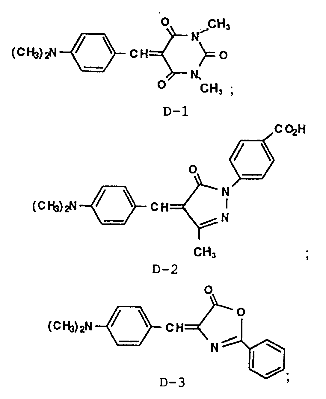

Particularly preferred phosphors are chosen from:
| Dye | Conc. (ppm) | MTF | Rel. Spd. | |
| - | 0 | .213 | 1 | Control |
| D-1 | 500 | .298 | .78 | Inventive |
| D-1 | 1000 | .312 | .68 | Inventive |
| D-1 | 2000 | .339 | .58 | Inventive |
| D-2 | 500 | .310 | .72 | Inventive |
| D-2 | 1000 | .334 | .65 | Inventive |
| D-2 | 2000 | .366 | .53 | Inventive |
| Wherein ppm is parts of acutance dye, by weight, per million parts of phosphor, by weight, and MTF is Modulation Transfer Function at 2 cycles per millimeter. |
Claims (10)
- An X-ray intensifying screen for a radiographic element comprisinga support;at least one active layer coated on said support, wherein said active layer comprisesa binder and a phosphor; andat least one layer comprises a dye defined as
 wherein R1 and R2 are independently chosen from hydrogen, alkyl and aryl;R3, R4, R5 and R6 are independently chosen from H, alkyl, halogen, alkoxy, hydroxy;R7 represents alkyl, aryl, -OR9, -NR10R11 wherein R9, R10 and R11 independently represent hydrogen, alkyl and aryl;R8 is alkyl, aryl, -CN, -COR12 wherein R12 is alkyl or aryl, -COOR13 wherein R13 is alkyl or aryl;R7 and R8 can be taken together to form a five or six membered ring or a substituted five or six membered ring;
wherein the active layer and the at least one layer comprising a dye are on the same side of the support, and
and
wherein at least 70 % of the emission of said X-ray intensifying screen has a wavelength of less than 400 nm. - The X-ray intensifying screen recited in claim 1 wherein at least one said phosphor is chosen from:(a) LnTaO4(b) LnTaO4:ReLn is yttrium, lutetium, gadolinium or combinations thereof;Ln is yttrium, lutetium, gadolinium or combinations thereof;Re is gadolinium, niobium, thulium, cerium or combinations thereof;(c) Ln2O3:ReLn is yttrium, gadolinium or combinations thereof;Re is a rare earth metal or combinations thereof;(d) BaFX:ReX is a halide, or combination of halides;Re is at least one rare earth metal;(e) ASO4:Eu wherein A is barium, strontium or a combination thereof;(f) CAWO4;(g) BaSi2O5:Pb;(h) BaSO4:Pb;(i) Mg4Ta2-2xNb2xO9:MyNay' whereinM is at least one of potassium, rubidium, cesium;x is 5x10⁻⁴ to 0.5;y is at least 2x10⁻³, andy+y' is less than 1.0;(j) hafnium zirconium germanate unactivated or activated with titanium;(k) Hf1-zZrzMyTixEeOa whereinE represents at least one of germanium and silicon;e is in the range of from greater than 1x10⁻³ to 0.1;M represents at least one alkali metal;x is in the range of from 3x10⁻⁴ to 1.0;y is in the range of 1x10⁻⁴ to 1.0;z is in the range of from 4x10⁻⁴ to 0.3; anda is sufficient to balance the charge;(l) hafnium zirconium oxide containing at least one alkali metal and activated with titanium, at least one rare earth element or a combination thereof;(m) Li2Hf1-x-y-zZrzSnyTixLwO3where L is at least one rare earth;w+x+y collectively are 0 to 0.2; andz is up to 0.2.
- The X-ray intensifying screen recited in claim 2 wherein at least one said phosphor is chosen from:(a) LnTaO4Ln is yttrium, lutetium, gadolinium or combinations thereof;(b) LnTaO4:ReLn is lutetium, gadolinium or combinations thereof;Re is gadolinium, niobium, thulium, cerium or combinations thereof;(c) Ln2O3:ReLn is yttrium, gadolinium or combinations thereof;Re is thulium, terbium, gadolinium or combinations thereof;(d) BaFX:ReX is chloride or bromide;Re is at least one rare earth metal, preferably europium;(e) BaSrSO4:Eu; and(f) CAWO4.
- The X-ray intensifying screen recited in claim 1 wherein said dye is
 wherein R1 and R2 are independently chosen from hydrogen, alkyl of 1-10 carbons, aryl of 6-24 carbons;R3, R4, R5 and R6 are independently chosen from H, alkyl of 1-10 carbons, halogen, alkoxy, hydroxy;R7 represents alkyl of 1-10 carbons, aryl of 6-24 carbons, -OR9, -NR10R11 wherein R9, R10 and R11 independently represent hydrogen, alkyl of 1-10 carbons, aryl of 6-24 carbons;R8 is alkyl of 1-10 carbons, aryl of 6-24 carbons, -CN, -COR12 wherein R12 is alkyl of 1-10 carbons or aryl of 6-24 carbons, -COOR13 wherein R13 is alkyl of 1-10 carbons or aryl of 6-24 carbons;R7 and R8 can be taken together to form a five or six membered ring or a substituted five or six membered ring.
 - The X-ray intensifying screen recited in claim 4 wherein said dye is chosen from:


- The X-ray intensifying screen recited in claim 1 wherein at least 80 % of the emission of said X-ray intensifying screen has a wavelength of less than 400 nm.
- A radiographic element comprising an X-ray intensifying screen as recited in claim 1 and a film element, wherein the active layer of the intensifying screen faces the film element.
- The X-ray intensifying screen recited in claim 1 comprisinga support with at least one layer coated thereon;at least one said layer comprises at least one phosphor dispersed in a binder wherein said phosphor is as defined in claim 3; andat least one said layer comprises a dye as defined in claim 1.
- A radiographic recording element comprising at least one X-ray intensifying screen as recited in claim 8 and a film element, wherein the active layer of the intensifying screen faces the film element.
- The radiographic recording element recited in claim 9 comprising two said X-ray intensifying screens.
Applications Claiming Priority (2)
| Application Number | Priority Date | Filing Date | Title |
|---|---|---|---|
| US13830793A | 1993-10-20 | 1993-10-20 | |
| US138307 | 1993-10-20 |
Publications (2)
| Publication Number | Publication Date |
|---|---|
| EP0650089A1 EP0650089A1 (en) | 1995-04-26 |
| EP0650089B1 true EP0650089B1 (en) | 2000-06-21 |
Family
ID=22481443
Family Applications (1)
| Application Number | Title | Priority Date | Filing Date |
|---|---|---|---|
| EP94115125A Expired - Lifetime EP0650089B1 (en) | 1993-10-20 | 1994-09-26 | High resolution radiographic recording element |
Country Status (3)
| Country | Link |
|---|---|
| EP (1) | EP0650089B1 (en) |
| JP (1) | JP2854810B2 (en) |
| DE (1) | DE69424981T2 (en) |
Families Citing this family (1)
| Publication number | Priority date | Publication date | Assignee | Title |
|---|---|---|---|---|
| DE10036940A1 (en) * | 2000-07-28 | 2002-02-07 | Patent Treuhand Ges Fuer Elektrische Gluehlampen Mbh | Luminescence conversion LED |
Family Cites Families (8)
| Publication number | Priority date | Publication date | Assignee | Title |
|---|---|---|---|---|
| US3418247A (en) | 1965-03-24 | 1968-12-24 | Rca Corp | Rare earth activated lanthanum and lutetium oxy-chalcogenide phosphors |
| US3617743A (en) | 1968-10-23 | 1971-11-02 | Gen Electric | X-ray image convertors utilizing lanthanum and gadolinium oxyhalide luminescent materials activated with terbium |
| BE757384A (en) * | 1969-10-13 | 1971-04-13 | Du Pont | DIRECT POSITIVE PHOTOGRAPHIC EMULSIONS |
| US4225653A (en) | 1979-03-26 | 1980-09-30 | E. I. Du Pont De Nemours And Company | X-ray intensifying screen based on rare earth tantalate |
| US4259588A (en) * | 1979-10-31 | 1981-03-31 | Eastman Kodak Company | Green-emitting X-ray intensifying screens |
| JPS58206678A (en) | 1982-05-28 | 1983-12-01 | Fuji Photo Film Co Ltd | Fluorescent material |
| US5112721A (en) * | 1990-01-29 | 1992-05-12 | E. I. Du Pont De Nemours And Company | Photopolymerizable compositions containing sensitizer mixtures |
| US5095218A (en) * | 1990-07-20 | 1992-03-10 | Eastman Kodak Company | X-ray intensifying screen with enhanced emission |
-
1994
- 1994-09-26 DE DE69424981T patent/DE69424981T2/en not_active Expired - Fee Related
- 1994-09-26 EP EP94115125A patent/EP0650089B1/en not_active Expired - Lifetime
- 1994-10-20 JP JP6282867A patent/JP2854810B2/en not_active Expired - Lifetime
Also Published As
| Publication number | Publication date |
|---|---|
| JPH07191197A (en) | 1995-07-28 |
| DE69424981D1 (en) | 2000-07-27 |
| EP0650089A1 (en) | 1995-04-26 |
| JP2854810B2 (en) | 1999-02-10 |
| DE69424981T2 (en) | 2001-01-11 |
Similar Documents
| Publication | Publication Date | Title |
|---|---|---|
| EP0407890B1 (en) | Cassette with intensifying screens to be used with an X-ray film | |
| JP3421400B2 (en) | Radiograph assembly, radiograph element and image forming method | |
| JPH06230524A (en) | Combination of picture formation | |
| JPH0296740A (en) | Intensifying screen | |
| JP2568330B2 (en) | Mixed phosphor X-ray intensifying screen with improved resolution | |
| EP0412730B1 (en) | An improved cassette and radiographic film combination | |
| EP0581065B1 (en) | Combination of photosensitive elements for use in radiography | |
| EP0860492B1 (en) | X-ray intensifying screen based on barium hafnium zirconium phosphate | |
| EP0614542B1 (en) | Arylidene sensitizing dyes for tabular grains | |
| EP0568686B1 (en) | Radiographic system with improved image quality | |
| EP0650089A1 (en) | High resolution radiographic recording element | |
| JP4435543B2 (en) | Radiographic imaging assembly | |
| US5430302A (en) | Lithium tantalate based X-ray intensifying screen | |
| EP0350883B1 (en) | Combination of photosensitive elements for use in radiography | |
| JP2969198B2 (en) | Ultraviolet film / screen combination to improve radiodiagnostic evaluation | |
| EP0611457B1 (en) | Radiographic materials with increased uv sensitivity | |
| WO1993001522A1 (en) | Single screen/film structure with greatly improved radiological properties | |
| JPS6261043A (en) | Radiation image forming method | |
| JP3635380B2 (en) | Assembly of silver halide photographic material and radiation intensifying screen and processing method | |
| JP2003014896A (en) | Radiation intensifying screen |
Legal Events
| Date | Code | Title | Description |
|---|---|---|---|
| PUAI | Public reference made under article 153(3) epc to a published international application that has entered the european phase |
Free format text: ORIGINAL CODE: 0009012 |
|
| AK | Designated contracting states |
Kind code of ref document: A1 Designated state(s): BE DE FR GB IT |
|
| 17P | Request for examination filed |
Effective date: 19950907 |
|
| RAP1 | Party data changed (applicant data changed or rights of an application transferred) |
Owner name: STERLING DIAGNOSTIC IMAGING, INC. |
|
| 17Q | First examination report despatched |
Effective date: 19981021 |
|
| GRAG | Despatch of communication of intention to grant |
Free format text: ORIGINAL CODE: EPIDOS AGRA |
|
| GRAG | Despatch of communication of intention to grant |
Free format text: ORIGINAL CODE: EPIDOS AGRA |
|
| GRAH | Despatch of communication of intention to grant a patent |
Free format text: ORIGINAL CODE: EPIDOS IGRA |
|
| GRAH | Despatch of communication of intention to grant a patent |
Free format text: ORIGINAL CODE: EPIDOS IGRA |
|
| GRAA | (expected) grant |
Free format text: ORIGINAL CODE: 0009210 |
|
| RAP1 | Party data changed (applicant data changed or rights of an application transferred) |
Owner name: AGFA-GEVAERT N.V. |
|
| AK | Designated contracting states |
Kind code of ref document: B1 Designated state(s): BE DE FR GB IT |
|
| PG25 | Lapsed in a contracting state [announced via postgrant information from national office to epo] |
Ref country code: IT Free format text: LAPSE BECAUSE OF FAILURE TO SUBMIT A TRANSLATION OF THE DESCRIPTION OR TO PAY THE FEE WITHIN THE PRE;WARNING: LAPSES OF ITALIAN PATENTS WITH EFFECTIVE DATE BEFORE 2007 MAY HAVE OCCURRED AT ANY TIME BEFORE 2007. THE CORRECT EFFECTIVE DATE MAY BE DIFFERENT FROM THE ONE RECORDED.SCRIBED TIME-LIMIT Effective date: 20000621 Ref country code: BE Free format text: LAPSE BECAUSE OF FAILURE TO SUBMIT A TRANSLATION OF THE DESCRIPTION OR TO PAY THE FEE WITHIN THE PRESCRIBED TIME-LIMIT Effective date: 20000621 |
|
| REF | Corresponds to: |
Ref document number: 69424981 Country of ref document: DE Date of ref document: 20000727 |
|
| ET | Fr: translation filed | ||
| REG | Reference to a national code |
Ref country code: GB Ref legal event code: 746 Effective date: 20010212 |
|
| PLBE | No opposition filed within time limit |
Free format text: ORIGINAL CODE: 0009261 |
|
| STAA | Information on the status of an ep patent application or granted ep patent |
Free format text: STATUS: NO OPPOSITION FILED WITHIN TIME LIMIT |
|
| 26N | No opposition filed | ||
| REG | Reference to a national code |
Ref country code: FR Ref legal event code: D6 |
|
| REG | Reference to a national code |
Ref country code: GB Ref legal event code: IF02 |
|
| PGFP | Annual fee paid to national office [announced via postgrant information from national office to epo] |
Ref country code: FR Payment date: 20030827 Year of fee payment: 10 |
|
| PGFP | Annual fee paid to national office [announced via postgrant information from national office to epo] |
Ref country code: GB Payment date: 20030828 Year of fee payment: 10 |
|
| PGFP | Annual fee paid to national office [announced via postgrant information from national office to epo] |
Ref country code: DE Payment date: 20030902 Year of fee payment: 10 |
|
| PG25 | Lapsed in a contracting state [announced via postgrant information from national office to epo] |
Ref country code: GB Free format text: LAPSE BECAUSE OF NON-PAYMENT OF DUE FEES Effective date: 20040926 |
|
| PG25 | Lapsed in a contracting state [announced via postgrant information from national office to epo] |
Ref country code: DE Free format text: LAPSE BECAUSE OF NON-PAYMENT OF DUE FEES Effective date: 20050401 |
|
| GBPC | Gb: european patent ceased through non-payment of renewal fee |
Effective date: 20040926 |
|
| PG25 | Lapsed in a contracting state [announced via postgrant information from national office to epo] |
Ref country code: FR Free format text: LAPSE BECAUSE OF NON-PAYMENT OF DUE FEES Effective date: 20050531 |
|
| REG | Reference to a national code |
Ref country code: FR Ref legal event code: ST |