EP0650024A1 - Tube element for laminated heat exchanger - Google Patents
Tube element for laminated heat exchanger Download PDFInfo
- Publication number
- EP0650024A1 EP0650024A1 EP94307738A EP94307738A EP0650024A1 EP 0650024 A1 EP0650024 A1 EP 0650024A1 EP 94307738 A EP94307738 A EP 94307738A EP 94307738 A EP94307738 A EP 94307738A EP 0650024 A1 EP0650024 A1 EP 0650024A1
- Authority
- EP
- European Patent Office
- Prior art keywords
- beads
- bead
- passage
- tube element
- heat exchanging
- Prior art date
- Legal status (The legal status is an assumption and is not a legal conclusion. Google has not performed a legal analysis and makes no representation as to the accuracy of the status listed.)
- Granted
Links
Images


Classifications
-
- F—MECHANICAL ENGINEERING; LIGHTING; HEATING; WEAPONS; BLASTING
- F28—HEAT EXCHANGE IN GENERAL
- F28F—DETAILS OF HEAT-EXCHANGE AND HEAT-TRANSFER APPARATUS, OF GENERAL APPLICATION
- F28F3/00—Plate-like or laminated elements; Assemblies of plate-like or laminated elements
- F28F3/02—Elements or assemblies thereof with means for increasing heat-transfer area, e.g. with fins, with recesses, with corrugations
- F28F3/04—Elements or assemblies thereof with means for increasing heat-transfer area, e.g. with fins, with recesses, with corrugations the means being integral with the element
- F28F3/042—Elements or assemblies thereof with means for increasing heat-transfer area, e.g. with fins, with recesses, with corrugations the means being integral with the element in the form of local deformations of the element
- F28F3/044—Elements or assemblies thereof with means for increasing heat-transfer area, e.g. with fins, with recesses, with corrugations the means being integral with the element in the form of local deformations of the element the deformations being pontual, e.g. dimples
-
- F—MECHANICAL ENGINEERING; LIGHTING; HEATING; WEAPONS; BLASTING
- F28—HEAT EXCHANGE IN GENERAL
- F28D—HEAT-EXCHANGE APPARATUS, NOT PROVIDED FOR IN ANOTHER SUBCLASS, IN WHICH THE HEAT-EXCHANGE MEDIA DO NOT COME INTO DIRECT CONTACT
- F28D1/00—Heat-exchange apparatus having stationary conduit assemblies for one heat-exchange medium only, the media being in contact with different sides of the conduit wall, in which the other heat-exchange medium is a large body of fluid, e.g. domestic or motor car radiators
- F28D1/02—Heat-exchange apparatus having stationary conduit assemblies for one heat-exchange medium only, the media being in contact with different sides of the conduit wall, in which the other heat-exchange medium is a large body of fluid, e.g. domestic or motor car radiators with heat-exchange conduits immersed in the body of fluid
- F28D1/03—Heat-exchange apparatus having stationary conduit assemblies for one heat-exchange medium only, the media being in contact with different sides of the conduit wall, in which the other heat-exchange medium is a large body of fluid, e.g. domestic or motor car radiators with heat-exchange conduits immersed in the body of fluid with plate-like or laminated conduits
- F28D1/0308—Heat-exchange apparatus having stationary conduit assemblies for one heat-exchange medium only, the media being in contact with different sides of the conduit wall, in which the other heat-exchange medium is a large body of fluid, e.g. domestic or motor car radiators with heat-exchange conduits immersed in the body of fluid with plate-like or laminated conduits the conduits being formed by paired plates touching each other
- F28D1/0325—Heat-exchange apparatus having stationary conduit assemblies for one heat-exchange medium only, the media being in contact with different sides of the conduit wall, in which the other heat-exchange medium is a large body of fluid, e.g. domestic or motor car radiators with heat-exchange conduits immersed in the body of fluid with plate-like or laminated conduits the conduits being formed by paired plates touching each other the plates having lateral openings therein for circulation of the heat-exchange medium from one conduit to another
- F28D1/0333—Heat-exchange apparatus having stationary conduit assemblies for one heat-exchange medium only, the media being in contact with different sides of the conduit wall, in which the other heat-exchange medium is a large body of fluid, e.g. domestic or motor car radiators with heat-exchange conduits immersed in the body of fluid with plate-like or laminated conduits the conduits being formed by paired plates touching each other the plates having lateral openings therein for circulation of the heat-exchange medium from one conduit to another the plates having integrated connecting members
- F28D1/0341—Heat-exchange apparatus having stationary conduit assemblies for one heat-exchange medium only, the media being in contact with different sides of the conduit wall, in which the other heat-exchange medium is a large body of fluid, e.g. domestic or motor car radiators with heat-exchange conduits immersed in the body of fluid with plate-like or laminated conduits the conduits being formed by paired plates touching each other the plates having lateral openings therein for circulation of the heat-exchange medium from one conduit to another the plates having integrated connecting members with U-flow or serpentine-flow inside the conduits
Definitions
- the present invention relates to a tube element which can be used in a laminated heat exchanger such as an evaporator, a condenser, a heater core or a radiator.
- beads are formed in the heat exchanging medium passages of the tube elements to distribute the flow of the heat exchanging medium and, at the same time, to increase the contact area with the heat exchanging medium as a means for improving the heat exchanging efficiency.
- This applicant also uses tube elements in which a plurality of round beads are press-formed into the formed plates that constitute the tube elements, as disclosed in, for example, Japanese Unexamined Patent Publication S63-153397.
- the tube element products of the prior art have a bead diameter of 3.8mm, a minimum bead spacing of 7.0mm, a tube element thickness of 2.9mm and a plate thickness of 0.57mm in the formed plates.
- the bead diameter or the minor axis is within the range of 3.5mm - 4.8mm
- the tube element thickness is within the range of 2.8mm - 3.4mm
- the plate thickness of the formed plates is within the range of 0.40mm - 0.57mm. Except for the bead spacing, regarding which we do not have information, our tube element fits within those ranges.
- the flow of heat exchanging medium tends to take the shortest path available and, in a tube element provided with a U-shaped heat exchanging medium passage 7, as in the tube element shown in Figure 2, the heat exchanging medium tends to run along the projection 10 at the center. Because the beads are formed over the entire passage at a consistent density in the tube element of the prior art, there is no difference in passage resistance over the entirety of the passage. As a result, the heat exchanging medium travels along the projection, leaving areas where the heat exchanging medium becomes stagnant, such as at the upper sides of the tube element.
- An object of the present invention is to provide a tube element which realizes an improvement in efficiency and which also makes it possible to manufacture a smaller heat exchanger.
- An additional object is to provide a tube element with an improved bead arrangement by taking into consideration the necessity to reduce the number of beads in dead water regions and the necessity to disperse the flow of fluid by adjusting the passage resistance, thus achieving an improvement in heat exchanging efficiency.
- the heat exchanging medium passes through without performing sufficient heat exchange thus degrading the heat exchanging performance.
- the heat transfer rate is improved by reducing the thickness of the formed plates but this results in reduced anticorrosion characteristics and reduced strength. If the thickness of the formed plates is increased and the thickness of the tube element remains the same, the heat exchanging medium passage becomes narrower, increasing the passage resistance.
- the present invention is a tube element for a laminated heat exchanger in which tube elements and fins are laminated alternately over a plurality of rows wherein the fluid passage for the heat exchanging medium is formed by butting two formed plates one to another with beads that are formed in the aforementioned tube element as projections within the aforementioned fluid passage, in such a manner that the width of the beads A and the spacing of the beads B are set at 2.0mm ⁇ A ⁇ 3.0mm and 3.5 ⁇ B ⁇ 6.3mm respectively.
- the tube element thickness H and the formed plate thickness T may be set within the ranges of 1.9mm ⁇ H ⁇ 2.7mm and 0.25mm ⁇ T ⁇ 0.47mm respectively.
- a plurality of bead rows which cross the direction of the fluid passage of the aforementioned heat exchanging medium at a right angle may be provided with the bead rows that lie adjacent to one another having different intervals between the beads so that the beads in adjacent bead rows are arranged in such a manner that the low-pressure zone that is created behind each bead in the direction in which the fluid passage is formed does not impinge on the beads that follow.
- the tube element may take a structure in which a plurality of bead rows which cross the fluid passage direction at a right angle are provided with the various bead rows that lie adjacent to one another being different in the areas where beads are not present and those areas where beads are not present in the aforementioned bead rows that lie adjacent to one another form a continuum.
- the bead arrangement reduces the dead water regions and the passage resistance, thus eliminating stagnation by distributing the heat exchanging medium evenly over the entirety of the passage. As a result, heat exchanging efficiency is further improved due to the improvement in the area where beads are not formed.
- the laminated heat exchanger 1 is an evaporator of, for example, the 4-pass type, in which fins 2 and tube elements 3 are alternately laminated over a plurality of rows.
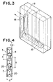
- Each tube element 3 is formed by bonding two formed plates 4, 4 at their peripheral edges and is provided with two tanks 5, 5 at one end on the upstream side of the airflow and the downstream side of the airflow. It is also provided with a heat exchanging medium passage 7 which lets heat exchanging medium travel from these tanks 5, 5 to the other end.
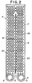
- Each formed plate 4 is formed by press machining an aluminum plate with, as shown in Figure 2, two vessel-like distended portions for tank formation 8, 8 at one end and a distended portion for passage formation 9 formed as a continuation of the distended portions 8, 8.
- the mounting indentation 11 for mounting the communicating pipe which is to be explained later, is provided between the distended portions for tank formation 8, 8 and at the other end of the formed plate 4 a projecting piece 12 (shown in Figure 1) is provided to prevent the fin 2 from falling off during assembly, before brazing.
- Each distended portion for tank formation 8 swells out more than the distended portion for passage formation 9.
- the projection 10 is bonded with its opposite projection when the formed plates 4 are bonded on their peripheral edges so that the projection 10 partitions the heat exchanging medium passage 7 except for the area close to the other end of the tube element 3, thus forming an overall U-
- the tanks 5 of neighboring tube elements 3 are butted to one another at the distended portions for tank formation 8 of the respective formed plates 4 and they communicate with one another through the communicating holes 13 which are formed at the distended portions for tank formation 8, except for the blind-type tank 5a, which is located on one side at the approximate center in the direction of lamination.
- the tube element 3a which is located at a specific position toward one side from the center, is not provided with the aforementioned mounting indentation 11 and one of its tank 5b on the side where the blind-type tank 5a is provided, is extended so that it will lie adjacent to the tank opposite.
- This extended tank 5b is connected with the communicating pipe 15 that is mounted in the mounting indentation 11.
- the intake/outlet port 16 is provided at one end of the heat exchanger in the direction of lamination which is furthest away from the extended tank 5b.
- This intake/outlet port 16 is, in turn, provided with a connecting portion 17 for connecting an expansion valve, a communicating passage 18, which communicates between the connecting portion 17 and the tank on the side where the blind tank is provided, and a communicating passage 19 which is connected to the aforementioned communicating pipe 15.
- heat exchanging medium flows in through one of the communicating passages, for example, communicating passage 19 connected to the intake/outlet port 16.
- the heat exchanging medium that has flowed in travels into one portion of the tank 5, which is divided approximately half, on the side of the blind-type tank 5a via the communicating pipe 15 and the extended tank 5b, then it travels upwards through the heat exchanging medium passage 7 along the projection 10, makes a U-turn at the top of the projection 10 to make the trip downward and finally reaches the tank which is on the opposite side from the blind-type tank 5a. After that it moves horizontally to the another tank 5 which is divided approximately half.
- the beads 20 are press formed as a part of the aforementioned formed plates 4.
- a plurality of bead rows are formed in such a manner that they lie at a right angle to the direction of the flow of the heat exchanging medium which travels through the heat exchanging medium passage 7, and each bead row is provided with a plurality of beads 20 that are positioned at even intervals.
- row n is constituted with four beads
- row n+1 is constituted with five beads
- the beads are positioned in bead rows that lie adjacent to one another in such a manner that the low-pressure zone that is created behind each bead in the direction in which the fluid passage is formed (the vertical direction in the figure) does not impinge on the following beads. All the beads in every other bead row are positioned in such a manner that they interleave with the low-pressure zones that are created behind the beads in the direction in which the fluid passage 7 is formed. Overall, the beads 20 are formed at a consistent density.
- the beads 20 described above project out from the internal surface of the formed plate towards the inside of the fluid passage 7. They are bonded with beads of the adjacent formed plate to improve the heat exchanging efficiency of the heat exchanging medium which flows through the heat exchanging medium passage 7.
- the tube element 3 if the area of the bottom portion of each bead, which is considered to begin at the point where the formed plate 4 starts to project out towards the inside of the fluid passage 7, (hereafter referred to as the bead size) is designated A, the spacing of the neighboring beads which are the closest to each other (hereafter referred to as the bead spacing) is designated B, the thickness of the portion of the tube element which constitutes the heat exchanging medium passage is designated H and the formed plate thickness is designated T, they fall within the following ranges; 2.0mm ⁇ A ⁇ 3.0mm, 3.5mn ⁇ B ⁇ 6.3mm, 1.9mm ⁇ H ⁇ 2.7mm, and 0.25mm ⁇ T ⁇ 0.47mm.
- the passage resistance increases and as the bead size A decreases, the passage resistance also decreases.
- the heat exchanging performance is relatively reduced.
- the number of beads becomes high, increasing the passage resistance, and as the bead spacing B becomes large, the number of beads becomes smaller, relatively reducing the passage resistance but at the same time reducing the heat exchanging performance as well.
- the wider the heat exchanging medium passage 7 can be made, which will improve the heat exchanging performance.
- the plate thickness is made too small, problems related to strength and anti-corrosion characteristics will arise.
- the heat exchanging medium passage 7 becomes narrower, increasing the passage resistance. All this means that, except for the formed plate thickness, the relationship between the heat exchanging performance and the passage resistance can be used as an index for evaluating the tube element 3.
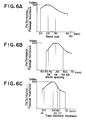
- This evaluation may be also made by assigning the heat exchanging performance/passage resistance as the axis of ordinates and each of the bead size, the bead spacing and the tube element thickness to the axis of abscissas, and these are shown in Figure 6.
- the index heat exchanging performance/passage resistance
- the index is set at 100 when the bead size is 2.5mm, the bead spacing is 4.8mm and the tube element thickness is 2.4mm.
- the index becomes lower if the size is either smaller or larger than 2.5m, as shown in Figure 6 (a).
- the bead size becomes larger, the passage resistance also becomes greater and if the bead size is increased to 3.8mm, which is common in the prior art, a good index cannot be achieved. Consequently, the upper limit of the bead size is set by using an index which is equivalent to the lower limit of the bead size or an index better than that, for reference, at A ⁇ 3.0mm.
- the index becomes lower when the bead spacing is either smaller or larger than 4.8mm. All in all, a good index is achieved within the spacing range of 3.5mm - 6.3mm. Since the smaller B is, the more difficult machining becomes and, at the same time, the passage resistance is greatly increased, it is necessary to set B at 3.5mm or more. Preferably, it should be set at 3.8mm or more to allow some tolerance in machining. Also, although the larger B is, the smaller the passage resistance becomes, the heat exchanging performance will be reduced as well.
- the upper limit for bead spacing is set by using an index which is equivalent to the lower limit value (3.5mm) of bead spacing or, an index better than that, at 6.3mm or less.
- the upper limit for bead spacing is set by using an index which is equivalent to the lower limit value (3.8mm) of the bead spacing or, an index better than that, at 5.8mm or less.
- the index for the tube element becomes lower if the thickness H is either smaller or larger than 2.4mm. Since the smaller H is, the more difficult machining becomes and, at the same time, the performance is reduced, it is necessary to set H at 1.9mm or more. Preferably, it should be set at 2.0mm or more, to allow some tolerance in machining. Also, it has been learned that the larger the thickness H is, the smaller the passage resistance becomes, and the heat exchanging efficiency will be reduced as well. Consequently, the upper limit for the thickness H is set by using the index which is equivalent to the lower limit value of the thickness or, an index better than that, at H ⁇ 2.7mm or, preferably H ⁇ 2.6.
- the optimal plate thickness T it is necessary to set the optimal plate thickness T by taking into consideration the relationship between the strength and anticorrosion characteristics of the formed plate and the passage resistance. It is, therefore, necessary to set the lower limit at T ⁇ 0.25mm by taking into consideration the strength and anticorrosion and to set the upper limit at T ⁇ 0.47mm by taking into consideration the deterioration of heat exchanging performance caused by the increase in passage resistance.
- a tube element in which the ranges stipulated above are obtained will be the best possible tube element considering and balancing the two requirements, i.e., an improvement in heat exchanging efficiency and a reduction in passage resistance. Furthermore, with such factors as strength and the like also taken into consideration, the tube element makes it possible to provide a more compact, light-weight heat exchanger compared to one which employs the tube elements of the prior art.
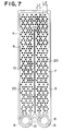
- Figure 7 shows another example of the formed plate 4 (second embodiment) that constitutes the tube element 3.
- the beads 20 are formed in a plurality of bead rows that cross the direction in which the heat exchanging medium passage is formed at a right angle, and the intervals at which beads are positioned are different between bead rows that lie adjacent to one another.
- 3 beads are provided at equal intervals of L2 and in row n+2
- in row n+3 three beads are provided at equal intervals L2 and so on.
- bead rows in which beads are provided at equal intervals L1 and bead rows in which beads are provided at equal intervals L2 are formed alternately.
- each interval L2 is twice the length of the interval L1.
- All the beads in every other bead row are positioned in such a manner that they interleave with the low-pressure zones that are created behind the beads in the direction in which said fluid passage 7 is formed (the vertical direction in the figure).
- they are positioned in such a manner that the bead which is closest to a given bead in an adjacent row lies at an angle of 30 degrees from that given bead to the direction in which the heat exchanging medium passage is formed.
- a regular pattern of bead groups emerge when viewed in the direction of 30 degrees, in which beads are arranged at intervals a and intervals b alternately.
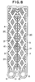
- the formed plate 4 that constitutes the tube element 3 may take the structure shown in another embodiment (third embodiment) presented in Figure 8, in which areas with no beads 20 are present in different locations in bead rows that lie adjacent to one another that cross the direction in which the heat exchanging medium passage 7 is formed at a right angle. These areas in the bead rows that lie adjacent to one another where beads are not formed, connect to form a passage 21, in which beads are not present in a direction which is different from the direction in which the heat exchanging medium passage 7 is formed. In this embodiment, the areas in which the beads 20 are not formed connect with one another continuously in the direction which is at an angle of 30 degrees to the direction in which the heat exchanging medium passage 7 is formed, in contrast to the tube element in the prior art in which beads are formed consistently.
- the number beads located in dead water regions is reduced, and areas where the passage resistance is small are created over the entirety of the heat exchanging medium passage 7 without reducing the heat exchanging efficiency.
- the distribution of the heat exchanging medium to those areas with low passage resistance is promoted, thereby distributing the heat exchanging medium over the entirety of the tube element and avoiding stagnation.
- an improvement in heat exchanging efficiency can be achieved.
- the following tube elements were tested; the tube element of the type shown in Figure 2, in which beads are provided at a consistent density (hereafter referred to as type 1), the tube element in the second embodiment (hereafter referred to as type 2) and the tube element in the third embodiment (hereafter referred to as type 3).
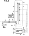
- a heating plate 22 was attached over the entirety of one of the surfaces of the distended portion for passage formation 9 with silicon adhesive, as shown in Figure 9.
- adiabatic material 30 was placed over the whole assemblage and an AC power source was connected to the heating plate 22 to supply a consistent quantity of heat to the tube element evenly.
- a specific quantity of tap water was supplied to the tube element via a 500mm-long intake pipe 23.
- the tap water supplied via the intake pipe 23 was monitored on the flow meter 25 and the flow rate of the tap water was adjusted to 5cc/sec, 10cc/sec and 20cc/ses.
- the surface temperature of the tube elements at those different flow rates was measured. The results are shown in the thermographic diagrams in Figs 10 - 12. Note that the values in Figures 10 - 12 indicate temperature readings (degrees Celsius).
- the average of the temperature differences (degrees Celsius) between the direction in which the fluid flows and the direction that crosses that direction at a right angle was measured with a group of thermocouples 29 provided at a plurality of specific locations (24 locations) on the surface of the tube element 4 (the surface on the opposite side from the side on which the heating plate is provided).
- the temperature difference between the intake and the outlet indicates that the larger the difference is, the more actively heat exchange is performed and the results of our experiment show that the temperature difference is somewhat greater in type 2 and type 3 than in type 1, although not significantly. With type 1, the temperature difference is greater at flow rates of 5cc/sec and 20cc/sec compared with type 2.
- water flow resistance As for water flow resistance, it was greater in both types 2 and 3 than in type 1 at 5cc/sec but it was smaller in both types 2 and 3 at 10 cc/sec and 20 cc/sec. Therefore, considering that the flow rate in an actual heat exchanger is normally approximately 10cc/sec, we can conclude that types 2 and 3 will have less water flow resistance. It was also noted that water flow resistance is smaller in type 3 than in type 2.
- the data obtained through the experiments indicate that the heat exchanging characteristics of type 2 and type 3 are improved even though the number of beads in those types is smaller than that of type 1, and we can safely say that in the type 2 and type 3 tube elements, the number of beads in the dead water regions is reduced, thus realizing bead arrangements that make it possible to distribute heat exchanging medium over the entirety of the passage without stagnation more completely than in type 1.
- tube elements used in an evaporator were explained, tube elements which satisfy the same requirements can be used in other types of laminated heat exchangers such as heater cores, condensers radiators and the like, and it goes without saying that higher efficiency and miniaturization can be realized in those applications as well. Also note that the present invention can be similarly applied whether a tank section is formed as part of the tube element or as a separate unit and mounted to the tube element.
Abstract
Description
- The present invention relates to a tube element which can be used in a laminated heat exchanger such as an evaporator, a condenser, a heater core or a radiator.
- In a heat exchanger that is formed by laminating fins and tube elements alternately in the prior art, beads are formed in the heat exchanging medium passages of the tube elements to distribute the flow of the heat exchanging medium and, at the same time, to increase the contact area with the heat exchanging medium as a means for improving the heat exchanging efficiency. This applicant also uses tube elements in which a plurality of round beads are press-formed into the formed plates that constitute the tube elements, as disclosed in, for example, Japanese Unexamined Patent Publication S63-153397. The tube element products of the prior art have a bead diameter of 3.8mm, a minimum bead spacing of 7.0mm, a tube element thickness of 2.9mm and a plate thickness of 0.57mm in the formed plates. According to an investigation conducted by this applicant, in the products manufactured by other companies, which use either round beads or elliptical beads, the bead diameter or the minor axis is within the range of 3.5mm - 4.8mm, the tube element thickness is within the range of 2.8mm - 3.4mm, and the plate thickness of the formed plates is within the range of 0.40mm - 0.57mm. Except for the bead spacing, regarding which we do not have information, our tube element fits within those ranges.
- It is commonly accepted in the prior art that the more beads there are in the tube element, the larger the area of contact between the tube element and the heat exchanging medium is, and consequently, the better the heat exchanging efficiency must be. However, if the number of beads is indiscriminately increased, the passage area of the heat exchanging medium passage is reduced, thereby increasing passage resistance and obstructing the flow of the heat exchanging medium. In contrast, if, in order to reduce the passage resistance, the beads are made smaller and the number of them is reduced, the area of contact with the heat exchanging medium will be insufficient, the heat transfer rate to the fins will be reduced and heat excnanging performance will be degraded. However, we must respond to the need for a smaller heat exchanger with better performance while considering these conflicting factors. Further improvement of the tube element is essential.
- It is also understood that if a plurality of obstacles A are placed sequentially in the direction of progress of a fluid, as shown in Figure 13, the flow of fluid that has come in contact with the obstacle A will be re-directed laterally from the obstacle A and will tend to flow between subsequent obstacles A without striking them, thereby leaving them in the so-called dead water regions. It is deduced that in tube elements in the prior art described above, there are a number of beads which do not fully contribute to the heat exchanging process because they are in a dead water region. Such beads in dead water regions are not merely superfluous, but add to passage resistance and should be eliminated. It is preferable to promote heat exchange by running as much heat exchanging medium as possible through the passage, with a minimum of passage resistance.
- Moreover, in addition to the problem of dead water regions described above, the flow of heat exchanging medium tends to take the shortest path available and, in a tube element provided with a U-shaped heat exchanging
medium passage 7, as in the tube element shown in Figure 2, the heat exchanging medium tends to run along theprojection 10 at the center. Because the beads are formed over the entire passage at a consistent density in the tube element of the prior art, there is no difference in passage resistance over the entirety of the passage. As a result, the heat exchanging medium travels along the projection, leaving areas where the heat exchanging medium becomes stagnant, such as at the upper sides of the tube element. - All of this indicates that there is room for improvement in the arrangement of beads in the tube element.
- An object of the present invention is to provide a tube element which realizes an improvement in efficiency and which also makes it possible to manufacture a smaller heat exchanger.
- An additional object is to provide a tube element with an improved bead arrangement by taking into consideration the necessity to reduce the number of beads in dead water regions and the necessity to disperse the flow of fluid by adjusting the passage resistance, thus achieving an improvement in heat exchanging efficiency.
- This applicant has determined the optimal dimensional relationship among bead size, bead spacing, tube element thickness and formed plate thickness through consideration of the following factors: (1) The larger the bead size, the greater the passage resistance and the smaller the bead size, the smaller the passage resistance. However, if the bead size is too small, the heat exchanging performance is relatively reduced. (2) The smaller the bead spacing, the greater the number of beads, thus increasing passage resistance. In contrast, if bead spacing is large, the number of beads is small, relatively reducing the heat exchanging performance. (3) The smaller the thickness of the tube element, the narrower the heat exchanging medium passage, thus increasing the passage resistance, and the greater the thickness of the tube element, the smaller the passage resistance. However, in this latter case, the heat exchanging medium passes through without performing sufficient heat exchange thus degrading the heat exchanging performance. (4) The heat transfer rate is improved by reducing the thickness of the formed plates but this results in reduced anticorrosion characteristics and reduced strength. If the thickness of the formed plates is increased and the thickness of the tube element remains the same, the heat exchanging medium passage becomes narrower, increasing the passage resistance.
- In summary, the present invention is a tube element for a laminated heat exchanger in which tube elements and fins are laminated alternately over a plurality of rows wherein the fluid passage for the heat exchanging medium is formed by butting two formed plates one to another with beads that are formed in the aforementioned tube element as projections within the aforementioned fluid passage, in such a manner that the width of the beads A and the spacing of the beads B are set at 2.0mm ≦ A ≦ 3.0mm and 3.5 ≦ B ≦ 6.3mm respectively.
- In addition, the tube element thickness H and the formed plate thickness T may be set within the ranges of 1.9mm ≦ H ≦ 2.7mm and 0.25mm ≦ T ≦ 0.47mm respectively.
- By determining an optimal dimensional relationship for the bead width A and the bead spacing B of the beads formed in the tube element and also for the tube element thickness H and the formed plate thickness T in this manner, an ideal tube element can be realized, which provides the best possible combination of heat transfer rate, passage resistance and strength, achieving consequently, the highest possible heat exchanging efficiency while making possible a smaller heat exchanger.
- In addition to the structure described above, a plurality of bead rows which cross the direction of the fluid passage of the aforementioned heat exchanging medium at a right angle may be provided with the bead rows that lie adjacent to one another having different intervals between the beads so that the beads in adjacent bead rows are arranged in such a manner that the low-pressure zone that is created behind each bead in the direction in which the fluid passage is formed does not impinge on the beads that follow. Or, the tube element may take a structure in which a plurality of bead rows which cross the fluid passage direction at a right angle are provided with the various bead rows that lie adjacent to one another being different in the areas where beads are not present and those areas where beads are not present in the aforementioned bead rows that lie adjacent to one another form a continuum.
- With such a structure, even though it may be outside the optimal dimensional ranges because of the areas where beads are not formed, the bead arrangement reduces the dead water regions and the passage resistance, thus eliminating stagnation by distributing the heat exchanging medium evenly over the entirety of the passage. As a result, heat exchanging efficiency is further improved due to the improvement in the area where beads are not formed.
- Also, by combining these structures, a tube element that provides both the optimal bead form and the optimal bead arrangement can be achieved.
- The above and other features of the invention and the concomitant advantages will be better understood and appreciated by persons skilled in the field to which the invention pertains in view of the following description given in conjunction with the accompanying drawings which illustrate preferred embodiments. In the drawings:
- Figure 1 shows an embodiment of a laminated heat exchanger in which (a) is a frontal view and (b) is a bottom view;
- Figure 2 is a frontal view of the formed plate (type 1) which constitutes the tube element used in the laminated heat exchanger shown in Figure 1;
- Figure 3 illustrates the flow of the heat exchanging medium in the laminated heat exchanger shown in Figure 1;
- Figure 4 is an enlarged cross section showing the beads in a tube element;
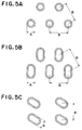
- Figures 5 (a), (b) and (c) illustrate the relationships among the bead form, the bead size A and the bead spacing B of the beads formed in the tube element;
- Figure 6 (a) is a characteristics chart which shows changes in the ratio of heat exchanging performance and passage resistance when bead size is changed, Figure 6 (b) is a characteristics chart which shows changes in the ratio of heat exchanging performance and passage resistance when the bead spacing is changed, and Figure 6 (c) is a characteristics chart which shows changes in the ratio of heat exchanging performance and passage resistance when the tube element thickness is changed;
- Figure 7 shows an example of a formed plate (type 2) used in the tube element in the laminated heat exchanger;
- Figure 8 shows another example of a formed plate (type 3) used in the tube element in the laminated heat exchanger;
- Figure 9 shows the testing device that was used for evaluating the performance of the tube elements;
- Figure 10 shows the temperature distribution for the tube element when the flow rate of tap water is set at 5cc/sec. Figure 10(a) shows the temperature distribution for the
type 1 tube element, Figure 10(b) shows the thermodynamic distribution for thetype 2 tube element and Figure 10(c) shows the temperature distribution for thetype 3 tube element; - Figure 11 shows the temperature distribution for the tube element when the flow rate of tap water is set at 10cc/sec, Figure 10(a) shows the temperature distribution for the
type 1 tube element, Figure 10(b) shows the temperature distribution for thetype 2 tube element and Figure 10(c) shows the temperature distribution for thetype 3 tube element; - Figure 12 shows the thermodynamic distribution for the tube element when the flow rate of tap water is set at 20cc/sec. Figure 10(a) shows the thermodynamic distribution for the
type 1 tube element Figure 10(b) shows the thermodynamic distribution for thetype 2 tube element and Figure 10(c) shows the thermodynamic distribution for thetype 3 tube element; - Figure 13 illustrates the flow of fluid past obstacles;
- The following is an explanation of the embodiments of the present invention in reference to the drawings.
- In Figure 1, the laminated
heat exchanger 1 is an evaporator of, for example, the 4-pass type, in whichfins 2 andtube elements 3 are alternately laminated over a plurality of rows. Eachtube element 3 is formed by bonding two formedplates tanks medium passage 7 which lets heat exchanging medium travel from thesetanks - Each formed
plate 4 is formed by press machining an aluminum plate with, as shown in Figure 2, two vessel-like distended portions fortank formation passage formation 9 formed as a continuation of the distendedportions projection 10, which extends from between the two distended portions fortank formation passage formation 9. Also, the mounting indentation 11 for mounting the communicating pipe which is to be explained later, is provided between the distended portions fortank formation fin 2 from falling off during assembly, before brazing. Each distended portion fortank formation 8 swells out more than the distended portion forpassage formation 9. Theprojection 10 is bonded with its opposite projection when the formedplates 4 are bonded on their peripheral edges so that theprojection 10 partitions the heat exchangingmedium passage 7 except for the area close to the other end of thetube element 3, thus forming an overall U-shaped passage. - The
tanks 5 of neighboringtube elements 3 are butted to one another at the distended portions fortank formation 8 of the respective formedplates 4 and they communicate with one another through the communicatingholes 13 which are formed at the distended portions fortank formation 8, except for the blind-type tank 5a, which is located on one side at the approximate center in the direction of lamination. - In addition, the
tube element 3a, which is located at a specific position toward one side from the center, is not provided with the aforementioned mounting indentation 11 and one of itstank 5b on the side where the blind-type tank 5a is provided, is extended so that it will lie adjacent to the tank opposite. Thisextended tank 5b is connected with the communicatingpipe 15 that is mounted in the mounting indentation 11. Also, at one end of the heat exchanger in the direction of lamination which is furthest away from theextended tank 5b, the intake/outlet port 16 is provided. This intake/outlet port 16 is, in turn, provided with a connectingportion 17 for connecting an expansion valve, a communicatingpassage 18, which communicates between the connectingportion 17 and the tank on the side where the blind tank is provided, and a communicatingpassage 19 which is connected to the aforementioned communicatingpipe 15. - In this structure, heat exchanging medium flows in through one of the communicating passages, for example, communicating
passage 19 connected to the intake/outlet port 16. The heat exchanging medium that has flowed in, travels into one portion of thetank 5, which is divided approximately half, on the side of the blind-type tank 5a via the communicatingpipe 15 and theextended tank 5b, then it travels upwards through the heat exchangingmedium passage 7 along theprojection 10, makes a U-turn at the top of theprojection 10 to make the trip downward and finally reaches the tank which is on the opposite side from the blind-type tank 5a. After that it moves horizontally to the anothertank 5 which is divided approximately half. Then it travels upwards through the heat exchangingmedium passage 7 along theprojection 10 again, and makes a U-turn at the top of theaforementioned projection 10 to make the trip downward. Finally, it flows out from thetank 5 which is located on the side where the blind-type tank 5a is provided via the communicating passage 18 (refer to the flow path shown in Figure 3). Because of this, the heat in the heat exchanging medium is transferred to thefins 2 during the process in which the heat exchanging medium flows through the heat exchangingmedium passage 7, to be heat exchanged with the air that passes between the fins. - Furthermore, the
beads 20 are press formed as a part of the aforementioned formedplates 4. In the case of the formedplate 4 shown in Figure 2, a plurality of bead rows are formed in such a manner that they lie at a right angle to the direction of the flow of the heat exchanging medium which travels through the heat exchangingmedium passage 7, and each bead row is provided with a plurality ofbeads 20 that are positioned at even intervals. In the figure, if row n is constituted with four beads, row n+1 is constituted with five beads, row n+2 with 4 beads and so on. The beads are positioned in bead rows that lie adjacent to one another in such a manner that the low-pressure zone that is created behind each bead in the direction in which the fluid passage is formed (the vertical direction in the figure) does not impinge on the following beads. All the beads in every other bead row are positioned in such a manner that they interleave with the low-pressure zones that are created behind the beads in the direction in which thefluid passage 7 is formed. Overall, thebeads 20 are formed at a consistent density. - As shown in Figure 4, the
beads 20 described above project out from the internal surface of the formed plate towards the inside of thefluid passage 7. They are bonded with beads of the adjacent formed plate to improve the heat exchanging efficiency of the heat exchanging medium which flows through the heat exchangingmedium passage 7. In thetube element 3, if the area of the bottom portion of each bead, which is considered to begin at the point where the formedplate 4 starts to project out towards the inside of thefluid passage 7, (hereafter referred to as the bead size) is designated A, the spacing of the neighboring beads which are the closest to each other (hereafter referred to as the bead spacing) is designated B, the thickness of the portion of the tube element which constitutes the heat exchanging medium passage is designated H and the formed plate thickness is designated T, they fall within the following ranges; 2.0mm ≦ A ≦ 3.0mm, 3.5mn ≦ B ≦ 6.3mm, 1.9mm ≦ H ≦ 2.7mm, and 0.25mm ≦ T ≦ 0.47mm. - For example, when circular beads, which have the overall shape of a circular, truncated cones, are arranged as shown in Figure 2, (the enlargement shown in Figure 5 (a)) i.e., when a plurality of beads are provided at specific intervals b in row n that runs in the direction that is at a right angle to the direction in which the heat exchanging medium passage is formed, and the beads in row n+1 are provided at the aforementioned specific intervals b in such a manner that each of the beads in row n+1 is at an equal distance from the nearest bead in row n, the diameter at the bottom of a bead is A and the aforementioned specific interval b is B. In the case shown in Figure 5(b), in which the beads in Figure 5 (a) above are replaced with oval shaped beads, or when the beads are positioned as shown in Figure 5 (c), the shortest distance between the centers of the various beads (i.e., the position in each bead where the minor axis and major axis intersect) is B.
- Generally speaking, it is desirable to have heat exchanging performance as high as possible and to minimize the passage resistance of the
heat exchanging passage 7 in thetube element 3. For example, as the bead size A increases, the passage resistance increases and as the bead size A decreases, the passage resistance also decreases. However, if the bead size is excessively small, the heat exchanging performance is relatively reduced. Also, with smaller bead spacing B, the number of beads becomes high, increasing the passage resistance, and as the bead spacing B becomes large, the number of beads becomes smaller, relatively reducing the passage resistance but at the same time reducing the heat exchanging performance as well. With the thickness of thetube element 3, too, the smaller the thickness, the narrower the heat exchangingmedium passage 7, increasing the passage resistance, and the larger the thickness H, the smaller the passage resistance. Here again, however, since the passage through which air travels becomes smaller, heat exchanging performance is reduced. Additionally, as the formed plate thickness becomes smaller, the wider the heat exchangingmedium passage 7 can be made, which will improve the heat exchanging performance. However, if the plate thickness is made too small, problems related to strength and anti-corrosion characteristics will arise. In contrast, if the plate thickness is increased, the heat exchangingmedium passage 7 becomes narrower, increasing the passage resistance. All this means that, except for the formed plate thickness, the relationship between the heat exchanging performance and the passage resistance can be used as an index for evaluating thetube element 3. - This evaluation may be also made by assigning the heat exchanging performance/passage resistance as the axis of ordinates and each of the bead size, the bead spacing and the tube element thickness to the axis of abscissas, and these are shown in Figure 6. The index (heat exchanging performance/passage resistance) is set at 100 when the bead size is 2.5mm, the bead spacing is 4.8mm and the tube element thickness is 2.4mm.
- Where the bead size is concerned, the index becomes lower if the size is either smaller or larger than 2.5m, as shown in Figure 6 (a). However, since machining becomes more difficult if the beads are smaller, and at the same time performance deteriorates, it is necessary to make sure that A ≧ 2mm. Also, note that as the bead size becomes larger, the passage resistance also becomes greater and if the bead size is increased to 3.8mm, which is common in the prior art, a good index cannot be achieved. Consequently, the upper limit of the bead size is set by using an index which is equivalent to the lower limit of the bead size or an index better than that, for reference, at A ≦ 3.0mm.
- As for the bead spacing, as shown in Figure 6 (b), the index becomes lower when the bead spacing is either smaller or larger than 4.8mm. All in all, a good index is achieved within the spacing range of 3.5mm - 6.3mm. Since the smaller B is, the more difficult machining becomes and, at the same time, the passage resistance is greatly increased, it is necessary to set B at 3.5mm or more. Preferably, it should be set at 3.8mm or more to allow some tolerance in machining. Also, although the larger B is, the smaller the passage resistance becomes, the heat exchanging performance will be reduced as well. Therefore, the upper limit for bead spacing is set by using an index which is equivalent to the lower limit value (3.5mm) of bead spacing or, an index better than that, at 6.3mm or less. The upper limit for bead spacing is set by using an index which is equivalent to the lower limit value (3.8mm) of the bead spacing or, an index better than that, at 5.8mm or less.
- Now, the index for the tube element, as shown in Figure 6 (c), becomes lower if the thickness H is either smaller or larger than 2.4mm. Since the smaller H is, the more difficult machining becomes and, at the same time, the performance is reduced, it is necessary to set H at 1.9mm or more. Preferably, it should be set at 2.0mm or more, to allow some tolerance in machining. Also, it has been learned that the larger the thickness H is, the smaller the passage resistance becomes, and the heat exchanging efficiency will be reduced as well. Consequently, the upper limit for the thickness H is set by using the index which is equivalent to the lower limit value of the thickness or, an index better than that, at H ≦ 2.7mm or, preferably H ≦ 2.6.
- As for the formed plate, as mentioned earlier, it is necessary to set the optimal plate thickness T by taking into consideration the relationship between the strength and anticorrosion characteristics of the formed plate and the passage resistance. It is, therefore, necessary to set the lower limit at T ≧ 0.25mm by taking into consideration the strength and anticorrosion and to set the upper limit at T ≦ 0.47mm by taking into consideration the deterioration of heat exchanging performance caused by the increase in passage resistance.
- As a result, a tube element in which the ranges stipulated above are obtained will be the best possible tube element considering and balancing the two requirements, i.e., an improvement in heat exchanging efficiency and a reduction in passage resistance. Furthermore, with such factors as strength and the like also taken into consideration, the tube element makes it possible to provide a more compact, light-weight heat exchanger compared to one which employs the tube elements of the prior art.
- Figure 7 shows another example of the formed plate 4 (second embodiment) that constitutes the
tube element 3. Here, thebeads 20 are formed in a plurality of bead rows that cross the direction in which the heat exchanging medium passage is formed at a right angle, and the intervals at which beads are positioned are different between bead rows that lie adjacent to one another. In this embodiment, when 5 beads are provided on the surface at equal intervals of L1 in row n, then in row n+1, 3 beads are provided at equal intervals of L2 and in row n+2, there are again 5 beads provided at equal intervals L1, and in row n+3, three beads are provided at equal intervals L2 and so on. In short, bead rows in which beads are provided at equal intervals L1 and bead rows in which beads are provided at equal intervals L2 are formed alternately. Furthermore, each interval L2 is twice the length of the interval L1. - All the beads in every other bead row are positioned in such a manner that they interleave with the low-pressure zones that are created behind the beads in the direction in which said
fluid passage 7 is formed (the vertical direction in the figure). In this embodiment, they are positioned in such a manner that the bead which is closest to a given bead in an adjacent row lies at an angle of 30 degrees from that given bead to the direction in which the heat exchanging medium passage is formed. As a result, a regular pattern of bead groups emerge when viewed in the direction of 30 degrees, in which beads are arranged at intervals a and intervals b alternately. - The formed
plate 4 that constitutes thetube element 3 may take the structure shown in another embodiment (third embodiment) presented in Figure 8, in which areas with nobeads 20 are present in different locations in bead rows that lie adjacent to one another that cross the direction in which the heat exchangingmedium passage 7 is formed at a right angle. These areas in the bead rows that lie adjacent to one another where beads are not formed, connect to form apassage 21, in which beads are not present in a direction which is different from the direction in which the heat exchangingmedium passage 7 is formed. In this embodiment, the areas in which thebeads 20 are not formed connect with one another continuously in the direction which is at an angle of 30 degrees to the direction in which the heat exchangingmedium passage 7 is formed, in contrast to the tube element in the prior art in which beads are formed consistently. - As a result, in both the second and third embodiments, the number beads located in dead water regions is reduced, and areas where the passage resistance is small are created over the entirety of the heat exchanging
medium passage 7 without reducing the heat exchanging efficiency. The distribution of the heat exchanging medium to those areas with low passage resistance is promoted, thereby distributing the heat exchanging medium over the entirety of the tube element and avoiding stagnation. Moreover, by the very act of reducing the number of beads, an improvement in heat exchanging efficiency can be achieved. - This applicant implemented the following tests in order to evaluate the tube elements which feature the bead arrangements described above, in comparison with a tube element in which beads are provided at a consistent density.
- The following tube elements were tested; the tube element of the type shown in Figure 2, in which beads are provided at a consistent density (hereafter referred to as type 1), the tube element in the second embodiment (hereafter referred to as type 2) and the tube element in the third embodiment (hereafter referred to as type 3). A
heating plate 22 was attached over the entirety of one of the surfaces of the distended portion forpassage formation 9 with silicon adhesive, as shown in Figure 9. Thenadiabatic material 30 was placed over the whole assemblage and an AC power source was connected to theheating plate 22 to supply a consistent quantity of heat to the tube element evenly. Next, a specific quantity of tap water was supplied to the tube element via a 500mm-long intake pipe 23. The tap water flowed from one tank to the next through the heat exchanging medium passage to be discharged from theoutlet pipe 24. The tap water supplied via theintake pipe 23 was monitored on theflow meter 25 and the flow rate of the tap water was adjusted to 5cc/sec, 10cc/sec and 20cc/ses. The surface temperature of the tube elements at those different flow rates was measured. The results are shown in the thermographic diagrams in Figs 10 - 12. Note that the values in Figures 10 - 12 indicate temperature readings (degrees Celsius). - In addition, the flow rate of tap water was varied at 5cc/sec, 10cc/sec and 20cc/sec, and a difference in water temperature (degrees Celsius) between the intake and the outlet was measured on a
temperature reader 28 from thethermocouples plate 4 at each flow rate setting. The results are shown in Table 1.(Table 1) 5 cc/ sec 10 cc/ sec 20 cc/ sec Type 1 7.0 3.3 1.7 Type 28.0 3.2 1.9 Type 37.2 3.3 1.7 - Also, the pressures at the intake and outlet are measured on the
pressure gauge 33 through the intakestatic pressure hole 31 formed in theintake pipe 23 and the outletstatic pressure hole 32 formed in theoutlet pipe 24 to determine the water flow resistance (mmHg) in thetube element 4. The results are shown in Table 2.(Table 2) 5 cc/ sec 10 cc/ sec 20 cc/ sec Type 1 6.5 9.0 16.6 Type 27.5 8.5 13.0 Type 37.2 8.4 12.5 - In addition, in order to determine the degree of inconsistency in heat exchange between the direction in which the heat exchanging
medium passage 7 is formed and the direction that crosses that direction at a right angle, the average of the temperature differences (degrees Celsius) between the direction in which the fluid flows and the direction that crosses that direction at a right angle was measured with a group ofthermocouples 29 provided at a plurality of specific locations (24 locations) on the surface of the tube element 4 (the surface on the opposite side from the side on which the heating plate is provided). - The results are shown in Table 3.
(Table 3) 5 cc/ sec 10 cc/ sec 20 cc/ sec Type 1 1.70 0.73 0.51 Type 21.34 0.52 0.39 Type 31.38 0.59 0.34 - The temperature difference between the intake and the outlet indicates that the larger the difference is, the more actively heat exchange is performed and the results of our experiment show that the temperature difference is somewhat greater in
type 2 andtype 3 than intype 1, although not significantly. Withtype 1, the temperature difference is greater at flow rates of 5cc/sec and 20cc/sec compared withtype 2. - As for water flow resistance, it was greater in both
types type 1 at 5cc/sec but it was smaller in bothtypes types type 3 than intype 2. - It is desirable that the isotherms in Figures 10 - 12 be horizontal (at a right angle to the heat exchanging medium passage). In other words, it is desirable to minimize the temperature difference in Table 3 as it will mean that heat exchange is performed consistently. From that viewpoint, both
types type 1. - In summary, the data obtained through the experiments indicate that the heat exchanging characteristics of
type 2 andtype 3 are improved even though the number of beads in those types is smaller than that oftype 1, and we can safely say that in thetype 2 andtype 3 tube elements, the number of beads in the dead water regions is reduced, thus realizing bead arrangements that make it possible to distribute heat exchanging medium over the entirety of the passage without stagnation more completely than intype 1. - All this leads to the conclusion that when the bead size A, the bead spacing B of neighboring beads which are closest to each other, the tube element thickness H and the formed plate thickness T fall within the ranges of 2.0mm ≦ A ≦ 3.0mm, 3.5mm ≦ B ≦ 6.3mm, 1.9mm ≦ H ≦ 2.7mm, 0.25mm ≦ T ≦ 0.47mm, respectively and the number of beads is reduced as shown in Figure 7 or Figure 8, although the beads are outside the dimensional ranges in those areas where the number of beads is reduced, the heat exchanging characteristics are improved as was demonstrated in the tests described above and an added effect of this reduced number of beads further improves the heat exchanging performance.
- Although in these embodiments, tube elements used in an evaporator were explained, tube elements which satisfy the same requirements can be used in other types of laminated heat exchangers such as heater cores, condensers radiators and the like, and it goes without saying that higher efficiency and miniaturization can be realized in those applications as well. Also note that the present invention can be similarly applied whether a tank section is formed as part of the tube element or as a separate unit and mounted to the tube element.
Claims (10)
- A tube element for a laminated heat exchanger, a plurality of which are laminated alternately with fins over a plurality of rows, in which a passage for heat exchanging medium is formed by butting two formed plates with beads projecting into said passage, wherein;
the width A of each of said beads and the spacing B of said beads formed in said tube element are within the ranges of:
2.0mm ≦ A ≦ 3.0mm, and
3.5mm ≦ B ≦ 6.3mm respectively. - A tube element for a laminated heat exchanger according to claim 1 wherein;
the thickness H of said tube element and the plate thickness of said formed plates are within the ranges of:
1.9mm ≦ H ≦ 2.7mm, and
0.25mm ≦ T ≦ 0.47mm respectively. - A tube element for a heat exchanger according to claim 1 or claim 2 that is provided with a plurality of bead rows are provided that run at a right angle to the direction in which said heat exchanging medium passage is formed, with said beads in each of said bead rows being positioned at equal intervals and said beads in bead rows that lie adjacent to one another being positioned so that they interleave with the low-pressure zones that are created behind said beads in the direction in which said passage is formed.
- A tube element for a laminated heat exchanger, a plurality of which are laminated alternately with fins over a plurality of rows, in which a passage for heat exchanging medium is formed by butting two formed plates with beads projecting into said passage, wherein;
a plurality of bead rows are provided that run at a right angle to the direction in which said passage is formed, said beads being provided at different intervals in bead rows that lie adjacent to one another, and said beads in said bead rows that lie adjacent to one another being positioned so that they interleave with the low-pressure zones that are created behind said beads in the direction in which said fluid passage is formed. - A tube element for a laminated heat exchanger, a plurality of which are laminated alternately with fins over a plurality of rows, in which a passage for heat exchanging medium is formed by butting two formed plates with beads projecting into said passage, wherein;
a plurality of bead rows are provided that run at a right angle to the direction in which said passage is formed, and areas where said beads are not formed are provided in different locations in said bead rows that lie adjacent to one another in such a manner that said areas where said beads are not formed in said bead rows that lie adjacent to one another form a continuum. - A tube element for a laminated heat exchanger according to claim 1 or claim 2 wherein;
a plurality of bead rows that run at a right angle to the direction in which said passage for heat exchanging medium is formed, are provided at different intervals in said bead rows which lie adjacent to one another and said beads in said bead rows that lie adjacent to one another is positioned so that they interleave with the low-pressure zones that are created behind the beads in the direction in which said fluid passage is formed. - A tube element for a laminated heat exchanger according to claim 1 claim 2 wherein;
a plurality of bead rows that run at a right angle to the direction in which said passage for heat exchanging medium is formed, and areas where beads are not formed are provided in different locations in bead rows that lie adjacent to one another in such a manner that said areas where beads are not formed in said bead rows that lie adjacent to one another form a continuum. - A tube element for a laminated heat exchanger according to claim 6 wherein;
a plurality of bead rows that run at a right angle to the direction in which said passage is formed are provided, and
bead rows in which beads are provided at specific intervals and
bead rows in which beads are provided at intervals twice said specific intervals are formed alternately. - A tube element for a laminated heat exchanger according to claim 6 wherein;
the bead which is closest to any given bead in the adjacent bead row is located so that it is at a 30° angle from said given bead to the direction in which said heat exchanging medium passage is formed. - A tube element for a laminated heat exchanger according to claim 7 wherein;
areas in which beads are not provided form a continuum in the direction which is at a 30° angle from the direction in which said heat exchanger medium passage is formed.
Applications Claiming Priority (6)
| Application Number | Priority Date | Filing Date | Title |
|---|---|---|---|
| JP28763193 | 1993-10-22 | ||
| JP287631/93 | 1993-10-22 | ||
| JP5300956A JP3028452B2 (en) | 1993-11-05 | 1993-11-05 | Tube element for stacked heat exchanger |
| JP300956/93 | 1993-11-05 | ||
| JP5345389A JPH07167581A (en) | 1993-10-22 | 1993-12-21 | Tube elements of lamination type heat exchanger |
| JP345389/93 | 1993-12-21 |
Publications (2)
| Publication Number | Publication Date |
|---|---|
| EP0650024A1 true EP0650024A1 (en) | 1995-04-26 |
| EP0650024B1 EP0650024B1 (en) | 1998-09-09 |
Family
ID=27337369
Family Applications (1)
| Application Number | Title | Priority Date | Filing Date |
|---|---|---|---|
| EP19940307738 Expired - Lifetime EP0650024B1 (en) | 1993-10-22 | 1994-10-21 | Tube element for laminated heat exchanger |
Country Status (3)
| Country | Link |
|---|---|
| EP (1) | EP0650024B1 (en) |
| KR (1) | KR100228503B1 (en) |
| DE (1) | DE69413173T2 (en) |
Cited By (9)
| Publication number | Priority date | Publication date | Assignee | Title |
|---|---|---|---|---|
| FR2783906A1 (en) | 1998-09-24 | 2000-03-31 | Valeo Climatisation | Plate heat exchanger for use in motor vehicles, comprises channels located between flat plates |
| WO2000022364A1 (en) * | 1998-10-15 | 2000-04-20 | Ebara Corporation | Plate type heat exchanger |
| EP1058079A3 (en) * | 1999-05-31 | 2001-04-11 | Mitsubishi Heavy Industries, Ltd. | Heat exchanger and method of making it |
| EP1114974A2 (en) * | 2000-01-08 | 2001-07-11 | Halla Climate Control Corp. | Plate for stack type heat exchangers and heat exchanger using such plates |
| EP1067350A3 (en) * | 1999-07-09 | 2002-07-31 | Ford Motor Company | Beaded plate for a heat exchanger and method of making same |
| EP1644683A2 (en) * | 2003-05-29 | 2006-04-12 | Halla Climate Control Corporation | Plate for heat exchanger |
| FR2906020A1 (en) * | 2006-09-15 | 2008-03-21 | Halla Climate Control Corp | Plate for e.g. fin tube type heat exchanger, has beads protruding toward channels to make flow of refrigerant in manner so that each bead is arranged in zigzag form, and other beads are arranged asymmetrically with respect to line |
| US7413003B2 (en) | 2006-09-15 | 2008-08-19 | Halla Climate Control Corporation | Plate for heat exchanger |
| EP3015809A1 (en) * | 2014-10-31 | 2016-05-04 | Danfoss A/S | A plate heat exchanger |
Citations (4)
| Publication number | Priority date | Publication date | Assignee | Title |
|---|---|---|---|---|
| US4800954A (en) * | 1986-12-18 | 1989-01-31 | Diesel Kiki Co., Ltd. | Laminated heat exchanger |
| GB2223091A (en) * | 1988-08-12 | 1990-03-28 | Calsonic Corp | Heat exchange tubes |
| US5111878A (en) * | 1991-07-01 | 1992-05-12 | General Motors Corporation | U-flow heat exchanger tubing with improved fluid flow distribution |
| US5125453A (en) * | 1991-12-23 | 1992-06-30 | Ford Motor Company | Heat exchanger structure |
-
1994
- 1994-10-21 EP EP19940307738 patent/EP0650024B1/en not_active Expired - Lifetime
- 1994-10-21 DE DE1994613173 patent/DE69413173T2/en not_active Expired - Fee Related
- 1994-10-22 KR KR1019940027061A patent/KR100228503B1/en not_active IP Right Cessation
Patent Citations (4)
| Publication number | Priority date | Publication date | Assignee | Title |
|---|---|---|---|---|
| US4800954A (en) * | 1986-12-18 | 1989-01-31 | Diesel Kiki Co., Ltd. | Laminated heat exchanger |
| GB2223091A (en) * | 1988-08-12 | 1990-03-28 | Calsonic Corp | Heat exchange tubes |
| US5111878A (en) * | 1991-07-01 | 1992-05-12 | General Motors Corporation | U-flow heat exchanger tubing with improved fluid flow distribution |
| US5125453A (en) * | 1991-12-23 | 1992-06-30 | Ford Motor Company | Heat exchanger structure |
Cited By (15)
| Publication number | Priority date | Publication date | Assignee | Title |
|---|---|---|---|---|
| FR2783906A1 (en) | 1998-09-24 | 2000-03-31 | Valeo Climatisation | Plate heat exchanger for use in motor vehicles, comprises channels located between flat plates |
| CN100347510C (en) * | 1998-10-15 | 2007-11-07 | 株式会社荏原制作所 | Plate type heat exchanger |
| WO2000022364A1 (en) * | 1998-10-15 | 2000-04-20 | Ebara Corporation | Plate type heat exchanger |
| US6681844B1 (en) | 1998-10-15 | 2004-01-27 | Ebara Corporation | Plate type heat exchanger |
| US6453989B1 (en) | 1999-05-31 | 2002-09-24 | Mitsubishi Heavy Industries, Ltd. | Heat exchanger |
| EP1058079A3 (en) * | 1999-05-31 | 2001-04-11 | Mitsubishi Heavy Industries, Ltd. | Heat exchanger and method of making it |
| EP1067350A3 (en) * | 1999-07-09 | 2002-07-31 | Ford Motor Company | Beaded plate for a heat exchanger and method of making same |
| EP1114974A2 (en) * | 2000-01-08 | 2001-07-11 | Halla Climate Control Corp. | Plate for stack type heat exchangers and heat exchanger using such plates |
| EP1114974B1 (en) * | 2000-01-08 | 2004-08-11 | Halla Climate Control Corp. | Plate for stack type heat exchangers and heat exchanger using such plates |
| EP1644683A2 (en) * | 2003-05-29 | 2006-04-12 | Halla Climate Control Corporation | Plate for heat exchanger |
| EP1644683A4 (en) * | 2003-05-29 | 2010-07-21 | Halla Climate Control Corp | Plate for heat exchanger |
| US7934541B2 (en) | 2003-05-29 | 2011-05-03 | Halla Climate Control Corporation | Plate for heat exchanger |
| FR2906020A1 (en) * | 2006-09-15 | 2008-03-21 | Halla Climate Control Corp | Plate for e.g. fin tube type heat exchanger, has beads protruding toward channels to make flow of refrigerant in manner so that each bead is arranged in zigzag form, and other beads are arranged asymmetrically with respect to line |
| US7413003B2 (en) | 2006-09-15 | 2008-08-19 | Halla Climate Control Corporation | Plate for heat exchanger |
| EP3015809A1 (en) * | 2014-10-31 | 2016-05-04 | Danfoss A/S | A plate heat exchanger |
Also Published As
| Publication number | Publication date |
|---|---|
| DE69413173D1 (en) | 1998-10-15 |
| DE69413173T2 (en) | 1999-06-02 |
| KR100228503B1 (en) | 1999-11-01 |
| EP0650024B1 (en) | 1998-09-09 |
Similar Documents
| Publication | Publication Date | Title |
|---|---|---|
| CA1313183C (en) | Embossed plate heat exchanger | |
| US4274482A (en) | Laminated evaporator | |
| US4971145A (en) | Heat exchanger header | |
| US6935418B1 (en) | Fluid conveying tube and vehicle cooler provided therewith | |
| US7055585B2 (en) | Layered evaporator for use in motor vehicle air conditioners or the like, layered heat exchanger for providing the evaporator, and refrigeration cycle system comprising the evaporator | |
| KR100950714B1 (en) | Plate for heat exchanger | |
| US4958681A (en) | Heat exchanger with bypass channel louvered fins | |
| JPH08285407A (en) | Laminated type heat exchanger | |
| US20100025025A1 (en) | Heat exchanger and manufacturing method of the same | |
| EP3199903B1 (en) | Heat exchanger and heat exchange method | |
| EP0650024A1 (en) | Tube element for laminated heat exchanger | |
| US6173764B1 (en) | Laminated heat exchanger | |
| US5662164A (en) | Laminated heat exchanger | |
| EP0650023B1 (en) | Multilayered heat exchanger | |
| JP2002130977A (en) | Heat exchanger | |
| JPH10292995A (en) | Lamination-type heat exchanger | |
| JPH0933187A (en) | Laminated heat exchanger | |
| US5667007A (en) | Laminated heat exchanger | |
| US5718284A (en) | Laminated heat exchanger | |
| CN112146484B (en) | Plate heat exchanger | |
| JPS61114094A (en) | Heat exchanger | |
| KR100528997B1 (en) | Multilayer Heat Exchanger | |
| JP2884201B2 (en) | Heat exchanger | |
| JP4638583B2 (en) | Fluid transport tube and automotive cooler comprising the tube | |
| US20230258410A1 (en) | Heat exchanger with optimized pressure loss |
Legal Events
| Date | Code | Title | Description |
|---|---|---|---|
| PUAI | Public reference made under article 153(3) epc to a published international application that has entered the european phase |
Free format text: ORIGINAL CODE: 0009012 |
|
| AK | Designated contracting states |
Kind code of ref document: A1 Designated state(s): DE FR GB IT SE |
|
| 17P | Request for examination filed |
Effective date: 19950502 |
|
| 17Q | First examination report despatched |
Effective date: 19960119 |
|
| GRAG | Despatch of communication of intention to grant |
Free format text: ORIGINAL CODE: EPIDOS AGRA |
|
| GRAG | Despatch of communication of intention to grant |
Free format text: ORIGINAL CODE: EPIDOS AGRA |
|
| GRAH | Despatch of communication of intention to grant a patent |
Free format text: ORIGINAL CODE: EPIDOS IGRA |
|
| GRAH | Despatch of communication of intention to grant a patent |
Free format text: ORIGINAL CODE: EPIDOS IGRA |
|
| GRAA | (expected) grant |
Free format text: ORIGINAL CODE: 0009210 |
|
| AK | Designated contracting states |
Kind code of ref document: B1 Designated state(s): DE FR GB IT SE |
|
| PG25 | Lapsed in a contracting state [announced via postgrant information from national office to epo] |
Ref country code: IT Free format text: LAPSE BECAUSE OF FAILURE TO SUBMIT A TRANSLATION OF THE DESCRIPTION OR TO PAY THE FEE WITHIN THE PRESCRIBED TIME-LIMIT;WARNING: LAPSES OF ITALIAN PATENTS WITH EFFECTIVE DATE BEFORE 2007 MAY HAVE OCCURRED AT ANY TIME BEFORE 2007. THE CORRECT EFFECTIVE DATE MAY BE DIFFERENT FROM THE ONE RECORDED. Effective date: 19980909 |
|
| PGFP | Annual fee paid to national office [announced via postgrant information from national office to epo] |
Ref country code: SE Payment date: 19981006 Year of fee payment: 5 |
|
| REF | Corresponds to: |
Ref document number: 69413173 Country of ref document: DE Date of ref document: 19981015 |
|
| PG25 | Lapsed in a contracting state [announced via postgrant information from national office to epo] |
Ref country code: SE Free format text: LAPSE BECAUSE OF FAILURE TO SUBMIT A TRANSLATION OF THE DESCRIPTION OR TO PAY THE FEE WITHIN THE PRESCRIBED TIME-LIMIT Effective date: 19981209 |
|
| ET | Fr: translation filed | ||
| PLBE | No opposition filed within time limit |
Free format text: ORIGINAL CODE: 0009261 |
|
| STAA | Information on the status of an ep patent application or granted ep patent |
Free format text: STATUS: NO OPPOSITION FILED WITHIN TIME LIMIT |
|
| 26N | No opposition filed | ||
| REG | Reference to a national code |
Ref country code: GB Ref legal event code: 732E |
|
| REG | Reference to a national code |
Ref country code: FR Ref legal event code: TP Ref country code: FR Ref legal event code: CD |
|
| REG | Reference to a national code |
Ref country code: GB Ref legal event code: IF02 |
|
| PGFP | Annual fee paid to national office [announced via postgrant information from national office to epo] |
Ref country code: GB Payment date: 20051019 Year of fee payment: 12 |
|
| PGFP | Annual fee paid to national office [announced via postgrant information from national office to epo] |
Ref country code: DE Payment date: 20061019 Year of fee payment: 13 |
|
| GBPC | Gb: european patent ceased through non-payment of renewal fee |
Effective date: 20061021 |
|
| PG25 | Lapsed in a contracting state [announced via postgrant information from national office to epo] |
Ref country code: GB Free format text: LAPSE BECAUSE OF NON-PAYMENT OF DUE FEES Effective date: 20061021 |
|
| PG25 | Lapsed in a contracting state [announced via postgrant information from national office to epo] |
Ref country code: DE Free format text: LAPSE BECAUSE OF NON-PAYMENT OF DUE FEES Effective date: 20080501 |
|
| REG | Reference to a national code |
Ref country code: FR Ref legal event code: ST Effective date: 20080630 |
|
| PGFP | Annual fee paid to national office [announced via postgrant information from national office to epo] |
Ref country code: FR Payment date: 20061010 Year of fee payment: 13 |
|
| PG25 | Lapsed in a contracting state [announced via postgrant information from national office to epo] |
Ref country code: FR Free format text: LAPSE BECAUSE OF NON-PAYMENT OF DUE FEES Effective date: 20071031 |