EP0649986B1 - Unified fuel pump assembly - Google Patents
Unified fuel pump assembly Download PDFInfo
- Publication number
- EP0649986B1 EP0649986B1 EP94115270A EP94115270A EP0649986B1 EP 0649986 B1 EP0649986 B1 EP 0649986B1 EP 94115270 A EP94115270 A EP 94115270A EP 94115270 A EP94115270 A EP 94115270A EP 0649986 B1 EP0649986 B1 EP 0649986B1
- Authority
- EP
- European Patent Office
- Prior art keywords
- shaft
- subassembly
- fuel pump
- pump assembly
- impeller
- Prior art date
- Legal status (The legal status is an assumption and is not a legal conclusion. Google has not performed a legal analysis and makes no representation as to the accuracy of the status listed.)
- Expired - Lifetime
Links
- 239000000446 fuel Substances 0.000 title claims description 50
- 239000012530 fluid Substances 0.000 claims description 24
- 238000005086 pumping Methods 0.000 claims description 18
- 239000007788 liquid Substances 0.000 claims description 9
- 230000000712 assembly Effects 0.000 description 2
- 238000000429 assembly Methods 0.000 description 2
- 230000002708 enhancing effect Effects 0.000 description 2
- 230000001965 increasing effect Effects 0.000 description 2
- 230000037361 pathway Effects 0.000 description 2
- 230000001133 acceleration Effects 0.000 description 1
- 238000009825 accumulation Methods 0.000 description 1
- 238000002485 combustion reaction Methods 0.000 description 1
- 238000006073 displacement reaction Methods 0.000 description 1
- 239000002828 fuel tank Substances 0.000 description 1
- 239000000411 inducer Substances 0.000 description 1
- 230000013011 mating Effects 0.000 description 1
- 230000003068 static effect Effects 0.000 description 1
Images

Classifications
-
- F—MECHANICAL ENGINEERING; LIGHTING; HEATING; WEAPONS; BLASTING
- F04—POSITIVE - DISPLACEMENT MACHINES FOR LIQUIDS; PUMPS FOR LIQUIDS OR ELASTIC FLUIDS
- F04D—NON-POSITIVE-DISPLACEMENT PUMPS
- F04D9/00—Priming; Preventing vapour lock
- F04D9/04—Priming; Preventing vapour lock using priming pumps; using booster pumps to prevent vapour-lock
-
- F—MECHANICAL ENGINEERING; LIGHTING; HEATING; WEAPONS; BLASTING
- F04—POSITIVE - DISPLACEMENT MACHINES FOR LIQUIDS; PUMPS FOR LIQUIDS OR ELASTIC FLUIDS
- F04C—ROTARY-PISTON, OR OSCILLATING-PISTON, POSITIVE-DISPLACEMENT MACHINES FOR LIQUIDS; ROTARY-PISTON, OR OSCILLATING-PISTON, POSITIVE-DISPLACEMENT PUMPS
- F04C11/00—Combinations of two or more machines or pumps, each being of rotary-piston or oscillating-piston type; Pumping installations
- F04C11/005—Combinations of two or more machines or pumps, each being of rotary-piston or oscillating-piston type; Pumping installations of dissimilar working principle
Definitions
- This invention relates generally to fuel pumps for combustion engines and more specifically relates to fuel pump assemblies having a vane type pump for supplying fuel to an engine in combination with a dynamic booster pump for delivering fuel from a supply source such as a fuel tank, to the inlet of the vane pump.
- Rotary vane type fuel pumps are well known in the aircraft engine art.
- design considerations and limitations have required such pumps to include axial shafts having journal ends of relatively small diameter.
- relatively small refers generally to the diameter of the journal ends of the shaft which are supported by rotary bearings, relative to the central rotor portion of the shaft.
- D diameter of the journal end
- journal end refers to the portion of the rotary shaft that is supported by rotary bearings; it will be understood in this regard that such portion of the shaft need not necessarily be located at the extreme end of the shaft.
- U.S. Patent No. 5 545 014 there is disclosed a new type of variable displacement vane pump in which the diameter of the rotary shaft is made significantly greater than it was in vane pumps of the prior art and which can be substantially uniform in diameter from end to end.
- the bearing support portions of the shaft i.e. the journal ends
- the present invention relates to this new type of vane pump and the specification of the U.S. Patent No. 5 545 014 is, accordingly, referred to expressly and incorporated by reference herein.
- windage refers to the energy losses incurred when a rotating or other moving surface, such as the surface of the rotary impeller in a booster pump, is constrained to move in close proximity to a stationary surface such as the inner surface of the housing for such a pump.
- Winddage losses also include the energy dissipated in the separate sets of rotary bearings used in both the vane pump and the booster pump.
- a unified fuel pump assembly of the type used aboard aircraft which comprises a housing, a pair of spaced apart rotary bearings mounted to the housing and an axially extending shaft supported by the bearings for rotation relative to the housing.
- the fuel pump assembly further comprises a vane pump subassembly having a plurality of radially displaceable pumping vanes extending radially from an axial portion of the shaft in peripherally spaced apart relationship, a root area of each of the pumping vanes being adjacent to the axial portion of the shaft.
- the fuel pump assembly further comprises a booster pump subassembly coupled to the shaft in axially spaced relationship to the vane pump subassembly and having a dynamic impeller axially supported by the shaft for rotation therewith.
- the dynamic impeller has an inlet opening, a plurality of outlet openings radially outwards of the inlet opening and a plurality of fluid passages extending from the inlet opening to the outlet openings.
- the fuel pump assembly comprises fluid passage means in the housing for guiding pumped fluid from the outlet openings of the impeller to the root areas of the pumping vanes.
- the radially outer diameter of the vane pump subassembly which diameter is defined by the radially outer end portions of the radially extending pumping vanes, is smaller than the outlet diameter of the dynamic impeller as defined by the outlet openings thereof.
- the large outlet diameter of the dynamic impeller results in a comparatively large total size of the fuel pump. It is further to be taken into account that a discharge chamber annularly extending around the dynamic impeller has to present a comparatively large cross section in order to be able to axially direct the fuel which has been centrifugally discharged by rotation of the dynamic impeller into the discharge chamber, to the vane pump in a flow enhancing manner.
- the fuel discharged by the booster pump not only has to pass the axial distance between the booster pump and the vane pump but also a radial distance between the large diameter discharge chamber and the small diameter vane pump. This means a long pathway for the fuel and accordingly high flow losses.
- a further fuel pump assembly is known from G.B. patent No. 636,712.
- This known fuel pump assembly comprises a vane pump subassembly and a booster pump subassembly.
- the vane pump subassembly and the booster pump subassembly each are mounted to an individual rotary shaft. This clearly implies a large total size of the fuel pump assembly. Furthermore, an enlarged number of component parts is necessary.
- a further fuel pump assembly is known from DE-AS 1 101 860.
- This known fuel pump assembly comprises a centrifugal pump subassembly having a dynamic impeller which centrifugally discharges fuel to be pumped.
- a vane pump subassembly for increasing the pressure of the fuel discharged by the centrifugal pump is not provided. Instead, there is provided a liquid ring pump subassembly for pumping gaseous components which have been separated from the fuel in the centrifugal pump.
- a further object of this invention is the provision of a unique engine fuel pump assembly having a larger diameter rotary shaft than in prior art vane pumps and a booster pump impeller diameter that is smaller than in prior art devices, and is not substantially larger than the diameter of said rotary shaft, to reduce the overall space/volume requirements of the assembly.
- a unified fuel pump assembly of the type used aboard aircraft comprising a housing, a pair of spaced-apart rotary bearings mounted to said housing, an axially extending shaft supported by said bearings for rotation relative to said housing, a vane pump subassembly having a plurality of radially displaceable pumping vanes extending radially from an axial portion of said shaft in peripherally spaced-apart relationship, a root area of each of said pumping vanes being adjacent to said axial portion of said shaft, said radially extending pumping vanes defining by their radially outer end portions a radially outer diameter of said vane pump subassembly, a booster pump subassembly coupled to said shaft in axially spaced relationship to said vane pump subassembly and having a dynamic impeller axially supported by said shaft for rotation therewith, said dynamic impeller having an inlet opening, a plurality of outlet openings radially outwards of said inlet
- the reduced outer diameter of the dynamic impeller results in a reduced total size of the fuel pump assembly.
- the reduced outer diameter of the dynamic impeller furthermore permits a configuration of a discharge chamber of the booster pump subassembly which is optimized with respect to frictional losses and at the same time does not compromise the desired small total size of the fuel pump assembly.
- the inventive solution permits shorter pathways for the fuel between the booster pump subassembly and the vane pump subassembly since the fuel merely has to be guided in substantially axial direction from the outlet openings of the booster pump subassembly to the root areas of the pumping vanes, without any radial route deviations.
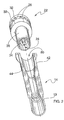
- Figure 1 may be seen to represent a unified fuel pump assembly 10 comprising a housing 12 incorporating a booster pump subassembly 20, a vane pump subassembly 40, an electric drive motor subassembly 60 and a liquid ring pump subassembly 70.
- Shaft 14 is supported for rotation within housing 12 by axially spaced-apart rotary bearings 16 and 17.
- Shaft 14 is illustrated separately in Figure 2 of the drawings, for purposes of clarity and explanation.
- Shaft 14 is provided with an axial portion 42 of given diameter having a plurality of peripherally spaced-apart slots 44 for supporting radially extending pumping vanes 46.
- the relationship and design requirements among shaft 14, slots 44 and vanes 46, which together define a significant part of vane pump subassembly 20, are more completely disclosed and explained in U.S. Patent No. 5 545 014 which has been incorporated herein by reference.
- Booster pump subassembly 20 operates in a conventional manner well known to those having skill in this art. More specifically, an impeller member 22 of generally cylindrical structure includes at least one inlet opening 24 and at least one outlet opening 26, with at least one but preferably a plurality of interior fluid conduits 30 connecting the inlet to the outlet. As the impeller member is rotated in a manner which will be made apparent, fluid drawn into the inlet 24 of impeller 22 is accelerated in a radially outward direction through conduits 30 under the influence of centrifugal force; acceleration in this manner increases both the static pressure and the velocity of the fluid that is released from the impeller through the discharge openings.
- the housing 12 of the unified assembly 10 is provided with internal fluid passages or passways 38 to guide pumped fluid from discharge openings 26 to the root area 48 of pumping vanes 46, adjacent to the outer surface of axial portion 42 of shaft 14.
- impeller member 22 of booster pump subassembly 20 is shown to be a standard form of radial blade dynamic impeller having a plurality of radially extending radial blades 32 that are connected in a well known manner to a screw-type inlet inducer 34.
- this particular type of impeller is illustrated in use in the booster stage subassembly 20, it should be understood that other types of dynamic impellers may be used.
- the rotating shaft 14 is shown coupled to an electric motor subassembly 60 which provides motive power for rotating the shaft 14 together with the vanes 46 of vane pump subassembly 40 and the impeller member 22 of booster pump subassembly 20.
- Electric motor 60 may be seen to comprise a rotor member 62, coupled directly to the journal of shaft 14 and a stator member 64, both being of any suitable well known design.
- fluid to be pumped is delivered to the inlet opening 24 of impeller 22 by means of an axial inlet passage 28 extending through the length of shaft 14.
- impeller 22 is provided with a cylindrical axially extending portion 36 that is dimensioned to mate in force fitting relationship with a corresponding receptacle opening 80 in one end of shaft 14.
- shaft 14 and impeller 22 which thus forms an axial extension from one end of the shaft, are shown to comprise a two-piece assembly in this embodiment, it should be understood that other, substantially equivalent one-piece structures may be used for the purposes herein disclosed.
- support member 13 includes a through opening 82 through which inlet fluid is guided from inlet port 84 into axial passage 28 in shaft 14, and ultimately into inlet 24 of impeller 22.
- Through opening 82 includes an inlet port 84 which guides inlet fluid from inlet port 84 into the liquid ring subassembly 70.
- Liquid ring assemblies are well known in the prior art as a means for eliminating accumulation of air bubbles in fluid pumping systems.
- the disclosed liquid ring subassembly comprises a paddle-like impeller 72 having a plurality of paddle elements 74 extending radially relative to, and rotating with, shaft 14 in eccentric, off-center rotating relationship to a cylindrical ring chamber 76.
- paddle elements 74 are shown mounted directly to electric motor rotor 62, to avoid unnecessary additional "windage" losses which would be incurred if a separate ring pump device was employed. It should be understood, however, that the paddle-like impeller 72 could be coupled directly to shaft 14 or to another rotating element, if it is desired to incorporate the features of this invention into an embodiment which does not include an electric motor subassembly as illustrated here.
- FIG. 1 An outlet opening 88 from ring chamber 76 is shown in Figure 1; it is positioned at or close to the point in the chamber where the distance between the outer wall 77 and the axis of rotation of paddles 74 is least, so that air trapped between the outer ring of fluid and the central axis of shaft 14 will be forced out of ring chamber 76 through opening 88 and into axial passage 28.
- a unified fuel pump assembly incorporating both a liquid ring subassembly 70 and an electric motor 60 have been disclosed herein as one form of this invention. It should be recognized readily, however, that other forms of this invention may incorporate other means of supplying rotational power to shaft 14, and other means of dealing with entrapped air balloons.
Landscapes
- Engineering & Computer Science (AREA)
- Mechanical Engineering (AREA)
- General Engineering & Computer Science (AREA)
- Structures Of Non-Positive Displacement Pumps (AREA)
Description
a housing, a pair of spaced-apart rotary bearings mounted to said housing, an axially extending shaft supported by said bearings for rotation relative to said housing, a vane pump subassembly having a plurality of radially displaceable pumping vanes extending radially from an axial portion of said shaft in peripherally spaced-apart relationship, a root area of each of said pumping vanes being adjacent to said axial portion of said shaft, said radially extending pumping vanes defining by their radially outer end portions a radially outer diameter of said vane pump subassembly, a booster pump subassembly coupled to said shaft in axially spaced relationship to said vane pump subassembly and having a dynamic impeller axially supported by said shaft for rotation therewith, said dynamic impeller having an inlet opening, a plurality of outlet openings radially outwards of said inlet opening and a plurality of fluid passages extending from said inlet opening to said outlet openings, said outlet openings defining an outlet diameter of said dynamic impeller, and fluid passage means in said housing for guiding pumped fluid from said outlet openings of said impeller to the root areas of said pumping vanes,
characterized in that said outlet diameter of said dynamic impeller is smaller than said radially outer diameter of said vane pump subassembly and not substantially larger than the diameter of said axial portion of said shaft.
Claims (8)
- A unified fuel pump assembly (10) of the type used aboard aircraft, comprisingcharacterized in that said outlet diameter of said dynamic impeller (22) is smaller than said radially outer diameter of said vane pump subassembly (40) and not substantially larger than the diameter of said axial portion of said shaft (14).a housing (12),a pair of spaced-apart rotary bearings (16, 17) mounted to said housing (12),an axially extending shaft (14) supported by said bearings (16, 17) for rotation relative to said housing (12),a vane pump subassembly (40) having a plurality of radially displaceable pumping vanes (46) extending radially from an axial portion of said shaft (14) in peripherally spaced-apart relationship, a root area (48) of each of said pumping vanes (46) being adjacent to said axial portion of said shaft (14), said radially extending pumping vanes (46) defining by their radially outer end portions a radially outer diameter of said vane pump subassembly (40),a booster pump subassembly (20) coupled to said shaft (14) in axially spaced relationship to said vane pump subassembly (40) and having a dynamic impeller (22) axially supported by said shaft (14) for rotation therewith, said dynamic impeller (22) having an inlet opening (24), a plurality of outlet openings (26) radially outwards of said inlet opening (24) and a plurality of fluid passages (30) extending from said inlet opening (24) to said outlet openings (26), said outlet openings (26) defining an outlet diameter of said dynamic impeller (22), andfluid passage means (38) in said housing (12) for guiding pumped fluid from said outlet openings (26) of said impeller (22) to the root areas (48) of said pumping vanes (46),
- A unified fuel pump assembly in accordance with Claim 1, wherein:said shaft (14) further includes an axial opening (28) extending from one end thereof to the other end thereof for providing fluid access to the said inlet opening (24) of said dynamic impeller (22).
- A unified fuel pump assembly in accordance with Claim 2, wherein:said dynamic impeller (22) includes a substantially cylindrical axial extension (36) thereof telescopically engaged with one end of said shaft (14) and having said inlet opening (24) of said dynamic impeller (22) formed as an axial opening in said axial extension (36) for fluid communication with the axial opening (28) in said shaft (14).
- A unified fuel pump assembly in accordance with one of claims 1 to 3, wherein:said assembly further includes a liquid ring pump subassembly (70) coupled to said shaft (14) for rotation therewith in axially spaced apart relationship to said vane pump subassembly (40) and said booster pump subassembly (20).
- A unified fuel pump assembly in accordance with Claim 4, wherein:said liquid ring pump subassembly (70) is positioned proximate one end of said shaft (14) for rotation therewith, and said dynamic impeller (22) of said booster pump subassembly (20) is coupled to the other end of said shaft (14).
- A unified fuel pump assembly in accordance with one of claims 2 to 5, wherein:said housing (12) further includes a support member (13) having a longitudinal opening therethrough in axial fluid communication with said axial opening (28) in said shaft (14), and at least one of said rotary bearings (16, 17) is coupled between and substantially coaxial with said support member (13) and said shaft (14).
- A unified fuel pump assembly in accordance with one of claims 1 to 6, wherein:said assembly further includes an electric motor subassembly (60) for imparting rotary motive power to said shaft (14) said electric motor subassembly (60) having a rotor element (62) coupled to said shaft (14) and a stator element (64) coupled to said housing (12).
- A unified fuel pump assembly in accordance with Claim 7, wherein:said fuel pump assembly further includes a liquid ring pump subassembly (70) having a plurality of paddle elements (74) coupled to the rotor element (62) of said electric motor subassembly (60), for rotation therewith.
Applications Claiming Priority (2)
| Application Number | Priority Date | Filing Date | Title |
|---|---|---|---|
| US08/142,274 US5413466A (en) | 1993-10-25 | 1993-10-25 | Unified fuel pump assembly |
| US142274 | 2002-05-08 |
Publications (2)
| Publication Number | Publication Date |
|---|---|
| EP0649986A1 EP0649986A1 (en) | 1995-04-26 |
| EP0649986B1 true EP0649986B1 (en) | 1998-12-16 |
Family
ID=22499253
Family Applications (1)
| Application Number | Title | Priority Date | Filing Date |
|---|---|---|---|
| EP94115270A Expired - Lifetime EP0649986B1 (en) | 1993-10-25 | 1994-09-28 | Unified fuel pump assembly |
Country Status (4)
| Country | Link |
|---|---|
| US (1) | US5413466A (en) |
| EP (1) | EP0649986B1 (en) |
| JP (1) | JP3372373B2 (en) |
| DE (1) | DE69415269T2 (en) |
Families Citing this family (7)
| Publication number | Priority date | Publication date | Assignee | Title |
|---|---|---|---|---|
| WO2001016491A1 (en) | 1999-09-01 | 2001-03-08 | Coltec Industries, Inc. | Centrifugal pump |
| US6623250B2 (en) | 2000-02-17 | 2003-09-23 | Goodrich Pump And Engine Control Systems, Inc. | Fuel metering unit |
| US6962485B2 (en) * | 2003-04-14 | 2005-11-08 | Goodrich Pump And Engine Control Systems, Inc. | Constant bypass flow controller for a variable displacement pump |
| US6996969B2 (en) * | 2003-09-09 | 2006-02-14 | Goodrich Pump & Engine Control Systems, Inc. | Multi-mode shutdown system for a fuel metering unit |
| US20050100447A1 (en) * | 2003-11-11 | 2005-05-12 | Desai Mihir C. | Flow control system for a gas turbine engine |
| GB0814025D0 (en) | 2008-08-01 | 2008-09-10 | Goodrich Control Sys Ltd | Fuel pumping system |
| CN102900569B (en) * | 2012-10-10 | 2015-04-08 | 南京工业大学 | Fuel pump |
Family Cites Families (14)
| Publication number | Priority date | Publication date | Assignee | Title |
|---|---|---|---|---|
| US2134686A (en) * | 1936-01-15 | 1938-11-01 | Gilbert & Barker Mfg Co | Pumping apparatus |
| GB636712A (en) * | 1945-09-19 | 1950-05-03 | Nash Engineering Co | Pump assembly |
| US2688925A (en) * | 1950-09-27 | 1954-09-14 | Thompson Prod Inc | Mixed flow multiple pump |
| US3026810A (en) * | 1956-09-12 | 1962-03-27 | Borg Warner | Variable displacement pump |
| DE1101860B (en) * | 1957-01-25 | 1961-03-09 | Nash Engineering Co | Fuel feed pump for internal combustion engines |
| US3141416A (en) * | 1960-05-27 | 1964-07-21 | United Aircraft Corp | Motor for pumping liquid metals |
| US3107626A (en) * | 1962-01-08 | 1963-10-22 | Borg Warner | Booster pumps |
| US3202101A (en) * | 1963-07-05 | 1965-08-24 | American Brake Shoe Co | Method and means for preventing cavitation in hydraulic piston and vane pumps |
| US3518028A (en) * | 1968-01-26 | 1970-06-30 | Trw Inc | Power reduction of liquid ring pumps |
| US4247263A (en) * | 1976-12-06 | 1981-01-27 | Chandler Evans Inc. | Pump assembly incorporating vane pump and impeller |
| US4275988A (en) * | 1978-12-18 | 1981-06-30 | Kalashnikov L F | Axial or worm-type centrifugal impeller pump |
| US4925372A (en) * | 1989-04-07 | 1990-05-15 | Vickers, Incorporated | Power transmission |
| US5061151A (en) * | 1990-02-22 | 1991-10-29 | Sundstrand Corporation | Centrifugal pump system with liquid ring priming pump |
| US5078573A (en) * | 1990-09-07 | 1992-01-07 | A. Ahlstrom Corporation | Liquid ring pump having tapered blades and housing |
-
1993
- 1993-10-25 US US08/142,274 patent/US5413466A/en not_active Expired - Lifetime
-
1994
- 1994-09-28 EP EP94115270A patent/EP0649986B1/en not_active Expired - Lifetime
- 1994-09-28 DE DE69415269T patent/DE69415269T2/en not_active Expired - Lifetime
- 1994-10-25 JP JP25862694A patent/JP3372373B2/en not_active Expired - Lifetime
Also Published As
| Publication number | Publication date |
|---|---|
| DE69415269T2 (en) | 1999-04-29 |
| DE69415269D1 (en) | 1999-01-28 |
| EP0649986A1 (en) | 1995-04-26 |
| JP3372373B2 (en) | 2003-02-04 |
| JPH084682A (en) | 1996-01-09 |
| US5413466A (en) | 1995-05-09 |
Similar Documents
| Publication | Publication Date | Title |
|---|---|---|
| CA2617657C (en) | Pressurized bearing system for submersible motor | |
| US5755554A (en) | Multistage pumps and compressors | |
| US3881839A (en) | Fuel pump | |
| US5061151A (en) | Centrifugal pump system with liquid ring priming pump | |
| US3751178A (en) | Pump | |
| EP2741793A1 (en) | Rotary pump comprising a rotor and delivery elements | |
| CN1139183A (en) | Circulating pump | |
| US5332355A (en) | Impelling apparatus | |
| WO1991013256A1 (en) | Combined electric motor and pump unit | |
| US5413466A (en) | Unified fuel pump assembly | |
| US3795459A (en) | Pitot pump with slotted inlet passages in rotor case | |
| EP1216359A1 (en) | Centrifugal pump | |
| US5582510A (en) | Assembly for feeding fuel from a supply tank to an internal combustion engine | |
| CA2382739C (en) | Pressurized bearing system for submersible motor | |
| AU8907591A (en) | Integrated centrifugal pump and motor | |
| US4047859A (en) | Axial vane pump with non-rotating vanes | |
| EP1532367A2 (en) | Centrifugal impeller and pump apparatus | |
| US4815930A (en) | Cavitating centrifugal pump | |
| US4655680A (en) | Continuous blade axial-flow friction drag pump | |
| US6474938B2 (en) | Fuel pump for gas turbines | |
| JP2021504618A (en) | Bending shaft hydraulic pump with centrifugal support | |
| RU2134821C1 (en) | Booster pumping unit | |
| JP2004515696A (en) | Feed pump | |
| BRPI0617523A2 (en) | rotor for one rotary machine and one rotary machine | |
| US5022228A (en) | Over the shaft fuel pumping system |
Legal Events
| Date | Code | Title | Description |
|---|---|---|---|
| PUAI | Public reference made under article 153(3) epc to a published international application that has entered the european phase |
Free format text: ORIGINAL CODE: 0009012 |
|
| AK | Designated contracting states |
Kind code of ref document: A1 Designated state(s): DE FR GB IT |
|
| 17P | Request for examination filed |
Effective date: 19950505 |
|
| 17Q | First examination report despatched |
Effective date: 19960201 |
|
| GRAG | Despatch of communication of intention to grant |
Free format text: ORIGINAL CODE: EPIDOS AGRA |
|
| GRAG | Despatch of communication of intention to grant |
Free format text: ORIGINAL CODE: EPIDOS AGRA |
|
| GRAH | Despatch of communication of intention to grant a patent |
Free format text: ORIGINAL CODE: EPIDOS IGRA |
|
| GRAH | Despatch of communication of intention to grant a patent |
Free format text: ORIGINAL CODE: EPIDOS IGRA |
|
| GRAA | (expected) grant |
Free format text: ORIGINAL CODE: 0009210 |
|
| AK | Designated contracting states |
Kind code of ref document: B1 Designated state(s): DE FR GB IT |
|
| REF | Corresponds to: |
Ref document number: 69415269 Country of ref document: DE Date of ref document: 19990128 |
|
| ET | Fr: translation filed | ||
| PLBE | No opposition filed within time limit |
Free format text: ORIGINAL CODE: 0009261 |
|
| STAA | Information on the status of an ep patent application or granted ep patent |
Free format text: STATUS: NO OPPOSITION FILED WITHIN TIME LIMIT |
|
| 26N | No opposition filed | ||
| REG | Reference to a national code |
Ref country code: GB Ref legal event code: IF02 |
|
| REG | Reference to a national code |
Ref country code: GB Ref legal event code: 732E |
|
| REG | Reference to a national code |
Ref country code: FR Ref legal event code: TP Ref country code: FR Ref legal event code: CA |
|
| REG | Reference to a national code |
Ref country code: FR Ref legal event code: RM |
|
| PGFP | Annual fee paid to national office [announced via postgrant information from national office to epo] |
Ref country code: GB Payment date: 20130926 Year of fee payment: 20 |
|
| PGFP | Annual fee paid to national office [announced via postgrant information from national office to epo] |
Ref country code: FR Payment date: 20130930 Year of fee payment: 20 Ref country code: DE Payment date: 20131111 Year of fee payment: 20 |
|
| PGFP | Annual fee paid to national office [announced via postgrant information from national office to epo] |
Ref country code: IT Payment date: 20130930 Year of fee payment: 20 |
|
| REG | Reference to a national code |
Ref country code: DE Ref legal event code: R071 Ref document number: 69415269 Country of ref document: DE |
|
| REG | Reference to a national code |
Ref country code: GB Ref legal event code: PE20 Expiry date: 20140927 |
|
| PG25 | Lapsed in a contracting state [announced via postgrant information from national office to epo] |
Ref country code: DE Free format text: LAPSE BECAUSE OF EXPIRATION OF PROTECTION Effective date: 20140930 |
|
| PG25 | Lapsed in a contracting state [announced via postgrant information from national office to epo] |
Ref country code: GB Free format text: LAPSE BECAUSE OF EXPIRATION OF PROTECTION Effective date: 20140927 |